Page 21 of 3000
2GR-FE ENGINE CONTROL SYSTEM – KNOCK SENSORES–521
ES
REMOVAL
1. DISCHARGE FUEL SYSTEM PRESSURE
(See page FU-13)
2. REMOVE V-BANK COVER SUB-ASSEMBLY (See
page EM-28)
3. DRAIN ENGINE COOLANT (See page CO-6)
4. REMOVE WINDSHIELD WIPER MOTOR ASSEMBLY
HINT:
(See page WW-4)
5. REMOVE FRONT OUTER COWL TOP PANEL SUB-
ASSEMBLY (See page EM-27)
6. REMOVE AIR CLEANER CAP SUB-ASSEMBLY (See
page ES-493)
7. REMOVE AIR CLEANER CASE SUB-ASSEMBLY (See
page EM-28)
8. REMOVE INTAKE AIR SURGE TANK ASSEMBLY
(a) Disconnect the 2 water by-pass hoses from the
throttle body [A].
(b) Disconnect the vapor feed hose [B].
(c) Disconnect the throttle body connector and clamp
[C].
(d) Disconnect the ventilation hose [D].
(e) Disconnect the union to check valve hose [E].
(f) Disconnect the connector [F].
A129464E07
A138457E04
A129467
Page 25 of 3000

EM–262GR-FE ENGINE MECHANICAL – ENGINE ASSEMBLY
EM
REMOVAL
1. DISCHARGE FUEL SYSTEM PRESSURE (See page
FU-13)
2. DISCHARGE REFRIGERANT FROM
REFRIGERATION SYSTEM (See page AC-172)
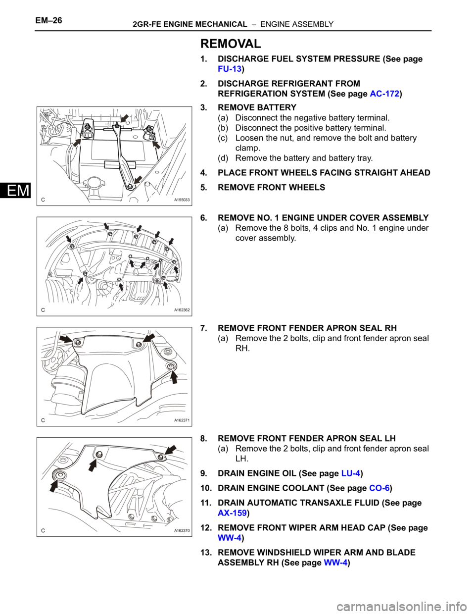
3. REMOVE BATTERY
(a) Disconnect the negative battery terminal.
(b) Disconnect the positive battery terminal.
(c) Loosen the nut, and remove the bolt and battery
clamp.
(d) Remove the battery and battery tray.
4. PLACE FRONT WHEELS FACING STRAIGHT AHEAD
5. REMOVE FRONT WHEELS
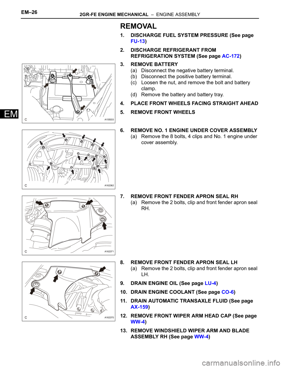
6. REMOVE NO. 1 ENGINE UNDER COVER ASSEMBLY
(a) Remove the 8 bolts, 4 clips and No. 1 engine under
cover assembly.
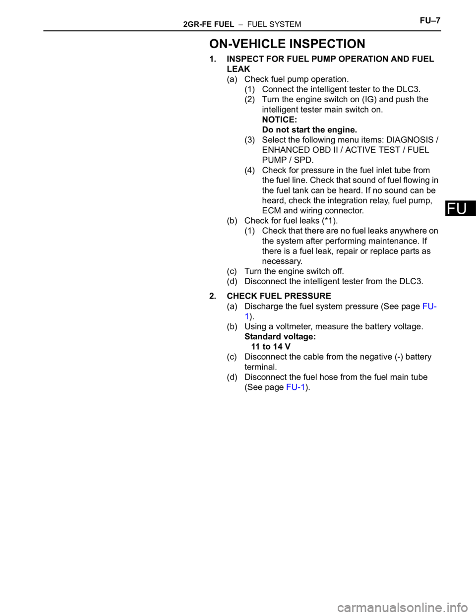
7. REMOVE FRONT FENDER APRON SEAL RH
(a) Remove the 2 bolts, clip and front fender apron seal
RH.
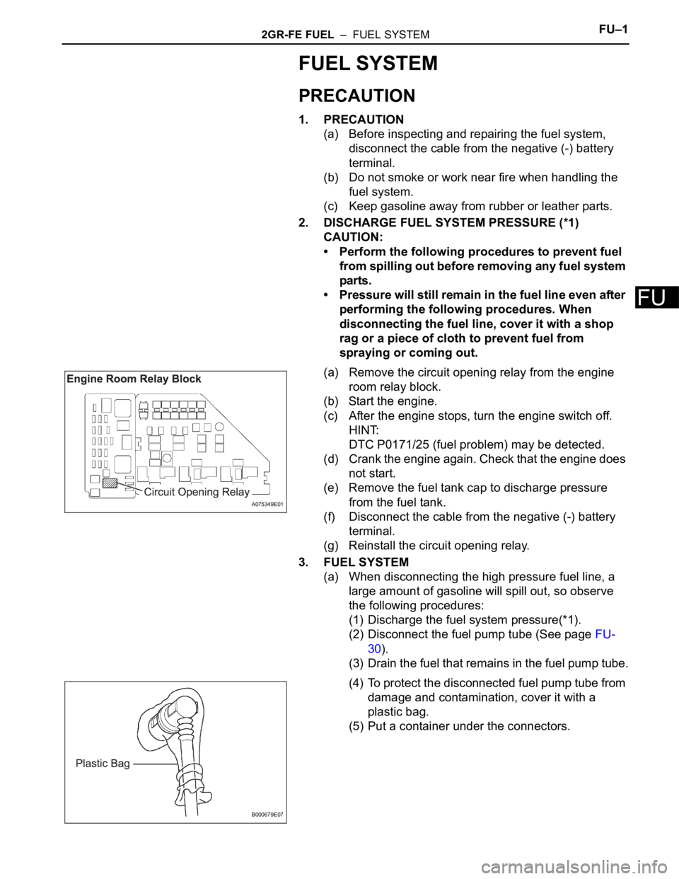
8. REMOVE FRONT FENDER APRON SEAL LH
(a) Remove the 2 bolts, clip and front fender apron seal
LH.
9. DRAIN ENGINE OIL (See page LU-4)
10. DRAIN ENGINE COOLANT (See page CO-6)
11. DRAIN AUTOMATIC TRANSAXLE FLUID (See page
AX-159)
12. REMOVE FRONT WIPER ARM HEAD CAP (See page
WW-4)
13. REMOVE WINDSHIELD WIPER ARM AND BLADE
ASSEMBLY RH (See page WW-4)
A155033
A162362
A162371
A162370
Page 705 of 3000

2GR-FE ENGINE CONTROL SYSTEM – SFI SYSTEMES–419
ES
Cut-off valve Located in fuel tank. Valve floats and closes when fuel tank is 100% full.
Purge VSV (Vacuum Switching Valve)Opens or closes line between canister and intake manifold. ECM uses purge VSV to control EVAP
purge flow. In order to discharge EVAP absorbed by canister to intake manifold, ECM opens purge
VSV. EVAP discharge volume to intake manifold is controlled by purge VSV duty cycle ratio
(current-carrying time). (Open: ON, Close: OFF)
Refueling valveControls EVAP pressure from fuel tank to canister. Valve consists of diaphragm, spring and
restrictor (diameter: 0.08 inch). When fuel vapor and pressure inside fuel tank increase, valve
opens. While EVAP is purged, valve closes and restrictor prevents a large amount of vacuum from
affecting pressure in fuel tank. Valve is opened while refueling. When valve is open, adding fuel into
fuel tank is possible.
Roll-over valveLocated in fuel tank. Valve closes by its own weight when vehicle overturns to prevent fuel from
spilling out.
Service port Used for connecting vacuum gauge for inspecting EVAP system.
Soak timerBuilt into ECM. To ensure accurate EVAP monitor, measures 5 hours (+/- 15 min.) after ignition
switch is turned off. This allows fuel to cool down, stabilizing Fuel Tank Pressure (FTP). When
approx. 5 hours elapsed, ECM activates.
Canister pump module Consists of (a) to (d) below. Pump module cannot be disassembled.
(a) Vent valveVents and closes EVAP system. When ECM turns valve ON, EVAP system is closed. When ECM
turns valve OFF, EVAP system is vented. Negative pressure (vacuum) is created in EVAP system
to check for EVAP leaks by closing purge VSV and vent valve (closed), and operating vacuum
pump are turned on (refer to fig. 1).
(b) Canister pressure sensorIndicates pressure as voltages. ECM supplies regulated 5 V to pressure sensor, and uses feedback
from sensor to monitor EVAP system pressure (refer to fig 2).
(c) Vacuum pump Creates negative pressure (vacuum) in EVAP system for leak check.
(d) 0.02 inch orificeHas an opening with 0.02 inch diameter. Vacuum is produced through orifice by closing purge VSV,
turning off vent valve and operating vacuum pump, to monitor 0.02 inch leak pressure. 0.02 inch
leak pressure indicates a small leak of EVAP. Component Operation
Page 836 of 3000
2GR-FE ENGINE CONTROL SYSTEM – KNOCK SENSORES–521
ES
REMOVAL
1. DISCHARGE FUEL SYSTEM PRESSURE
(See page FU-13)
2. REMOVE V-BANK COVER SUB-ASSEMBLY (See
page EM-28)
3. DRAIN ENGINE COOLANT (See page CO-6)
4. REMOVE WINDSHIELD WIPER MOTOR ASSEMBLY
HINT:
(See page WW-4)
5. REMOVE FRONT OUTER COWL TOP PANEL SUB-
ASSEMBLY (See page EM-27)
6. REMOVE AIR CLEANER CAP SUB-ASSEMBLY (See
page ES-493)
7. REMOVE AIR CLEANER CASE SUB-ASSEMBLY (See
page EM-28)
8. REMOVE INTAKE AIR SURGE TANK ASSEMBLY
(a) Disconnect the 2 water by-pass hoses from the
throttle body [A].
(b) Disconnect the vapor feed hose [B].
(c) Disconnect the throttle body connector and clamp
[C].
(d) Disconnect the ventilation hose [D].
(e) Disconnect the union to check valve hose [E].
(f) Disconnect the connector [F].
A129464E07
A138457E04
A129467
Page 985 of 3000

EM–262GR-FE ENGINE MECHANICAL – ENGINE ASSEMBLY
EM
REMOVAL
1. DISCHARGE FUEL SYSTEM PRESSURE (See page
FU-13)
2. DISCHARGE REFRIGERANT FROM
REFRIGERATION SYSTEM (See page AC-172)
3. REMOVE BATTERY
(a) Disconnect the negative battery terminal.
(b) Disconnect the positive battery terminal.
(c) Loosen the nut, and remove the bolt and battery
clamp.
(d) Remove the battery and battery tray.
4. PLACE FRONT WHEELS FACING STRAIGHT AHEAD
5. REMOVE FRONT WHEELS
6. REMOVE NO. 1 ENGINE UNDER COVER ASSEMBLY
(a) Remove the 8 bolts, 4 clips and No. 1 engine under
cover assembly.
7. REMOVE FRONT FENDER APRON SEAL RH
(a) Remove the 2 bolts, clip and front fender apron seal
RH.
8. REMOVE FRONT FENDER APRON SEAL LH
(a) Remove the 2 bolts, clip and front fender apron seal
LH.
9. DRAIN ENGINE OIL (See page LU-4)
10. DRAIN ENGINE COOLANT (See page CO-6)
11. DRAIN AUTOMATIC TRANSAXLE FLUID (See page
AX-159)
12. REMOVE FRONT WIPER ARM HEAD CAP (See page
WW-4)
13. REMOVE WINDSHIELD WIPER ARM AND BLADE
ASSEMBLY RH (See page WW-4)
A155033
A162362
A162371
A162370
Page 1117 of 3000

2GR-FE FUEL – FUEL SYSTEMFU–7
FU
ON-VEHICLE INSPECTION
1. INSPECT FOR FUEL PUMP OPERATION AND FUEL
LEAK
(a) Check fuel pump operation.
(1) Connect the intelligent tester to the DLC3.
(2) Turn the engine switch on (IG) and push the
intelligent tester main switch on.
NOTICE:
Do not start the engine.
(3) Select the following menu items: DIAGNOSIS /
ENHANCED OBD II / ACTIVE TEST / FUEL
PUMP / SPD.
(4) Check for pressure in the fuel inlet tube from
the fuel line. Check that sound of fuel flowing in
the fuel tank can be heard. If no sound can be
heard, check the integration relay, fuel pump,
ECM and wiring connector.
(b) Check for fuel leaks (*1).
(1) Check that there are no fuel leaks anywhere on
the system after performing maintenance. If
there is a fuel leak, repair or replace parts as
necessary.
(c) Turn the engine switch off.
(d) Disconnect the intelligent tester from the DLC3.
2. CHECK FUEL PRESSURE
(a) Discharge the fuel system pressure (See page FU-
1).
(b) Using a voltmeter, measure the battery voltage.
Standard voltage:
11 to 14 V
(c) Disconnect the cable from the negative (-) battery
terminal.
(d) Disconnect the fuel hose from the fuel main tube
(See page FU-1).
Page 1119 of 3000
2GR-FE FUEL – FUEL INJECTORFU–13
FU
REMOVAL
1. DISCHARGE FUEL SYSTEM PRESSURE
HINT:
See page FU-1.
2. DISCONNECT CABLE FROM NEGATIVE BATTERY
TERMINAL
3. REMOVE NO. 1 ENGINE UNDER COVER
4. DRAIN ENGINE COOLANT (See page CO-6)
5. REMOVE FRONT WIPER ARM HEAD CAP (See page
WW-4)
6. REMOVE FRONT WIPER ARM RH (See page WW-4)
7. REMOVE FRONT WIPER ARM LH (See page WW-4)
8. REMOVE COWL TOP VENTILATOR LOUVER SUB-
ASSEMBLY (See page WW-4)
9. REMOVE WINDSHIELD WIPER MOTOR AND LINK
ASSEMBLY (See page WW-4)
10. REMOVE NO. 1 COWL TOP TO COWL BRACE INNER
(a) Remove the 2 bolts and the No. 1 cowl top to cowl
brace inner.
11. REMOVE COWL TOP PANEL SUB-ASSEMBLY
OUTER FRONT
(a) Remove the wire harness clamp.
(b) Disconnect the fuel pump resistor connector.
(c) Remove the 7 bolts and the cowl top panel outer
front.
12. REMOVE V-BANK COVER SUB-ASSEMBLY (See
page EM-28)
13. REMOVE AIR CLEANER CAP SUB-ASSEMBLY
(a) Disconnect the 3 vacuum hoses.
A162429
A162430
A135112E01
Page 1122 of 3000

2GR-FE FUEL – FUEL SYSTEMFU–1
FU
FUEL SYSTEM
PRECAUTION
1. PRECAUTION
(a) Before inspecting and repairing the fuel system,
disconnect the cable from the negative (-) battery
terminal.
(b) Do not smoke or work near fire when handling the
fuel system.
(c) Keep gasoline away from rubber or leather parts.
2. DISCHARGE FUEL SYSTEM PRESSURE (*1)
CAUTION:
• Perform the following procedures to prevent fuel
from spilling out before removing any fuel system
parts.
• Pressure will still remain in the fuel line even after
performing the following procedures. When
disconnecting the fuel line, cover it with a shop
rag or a piece of cloth to prevent fuel from
spraying or coming out.
(a) Remove the circuit opening relay from the engine
room relay block.
(b) Start the engine.
(c) After the engine stops, turn the engine switch off.
HINT:
DTC P0171/25 (fuel problem) may be detected.
(d) Crank the engine again. Check that the engine does
not start.
(e) Remove the fuel tank cap to discharge pressure
from the fuel tank.
(f) Disconnect the cable from the negative (-) battery
terminal.
(g) Reinstall the circuit opening relay.
3. FUEL SYSTEM
(a) When disconnecting the high pressure fuel line, a
large amount of gasoline will spill out, so observe
the following procedures:
(1) Discharge the fuel system pressure(*1).
(2) Disconnect the fuel pump tube (See page FU-
30).
(3) Drain the fuel that remains in the fuel pump tube.
(4) To protect the disconnected fuel pump tube from
damage and contamination, cover it with a
plastic bag.
(5) Put a container under the connectors.
A075349E01
B000679E07