2007 TOYOTA SIENNA Steering
[x] Cancel search: SteeringPage 318 of 3000
2GR-FE ENGINE CONTROL SYSTEM – SFI SYSTEMES–1
ES
SFI SYSTEM
PRECAUTION
1. INITIALIZATION
NOTICE:
• Perform RESET MEMORY (AT initialization) when
replacing the automatic transaxle assembly, engine
assembly or ECM (See page AX-16).
• Perform REGISTRATION (VIN registration) when
replacing the ECM (See page ES-15).
HINT:
Initialization cannot be completed by only removing the
battery.
2. FOR USING INTELLIGENT TESTER
CAUTION:
Observe the following items for safety reasons:
• Before using the tester, read the instruction
manual.
• Prevent the tester cable from being caught on the
pedals, shift lever and steering wheel when
driving with the tester connected to the vehicle.
• When driving the vehicle for testing purposes
using the tester, two persons are required. One is
for driving the vehicle, and the other operates the
tester.
3. FOR USING BATTERY DURING INSPECTION
(a) While using the battery during inspection, do not
bring the positive and negative tester probes too
close to each other as a short circuit may occur.
4. COOLING FAN SYSTEM
NOTICE:
• When the ignition switch is turned off and the engine
temperature is high, the cooling fans may operate for
approximately 3 minutes.
• After turning the ignition switch off, keep hands and
objects away from the fans when they are operating.
HINT:
If all of the following are met for a certain period of time during
a few minute period immediately before the engine is
stopped, the electric fans will continue to operate for 3
minutes after the engine is stopped. This is performed to
ensure restartability and stabilize idle speed.
– The intelligent tester indicates a very high coolant
temperature.
– The intelligent tester indicates a high outside air
temperature.
– The vehicle has been driven under high load (driving on an
uphill or equivalent).
The following sensors are used for this control:
– Coolant temperature sensor
– Outside air temperature sensor
–MAF sensor
– Vehicle speed sensors
Page 366 of 3000

ES–482GR-FE ENGINE CONTROL SYSTEM – SFI SYSTEM
ES
O2FT B2 S2 Fuel trim at heated oxygen sensor Same as SHORT FT #2
AF FT B1 S1 Fuel trim at A/F sensor -
AF FT B2 S1 Fuel trim at A/F sensor -
CAT TEMP B1 S1 Catalyst temperature -
CAT TEMP B2 S1 Catalyst temperature -
CAT TEMP B1 S2 Catalyst temperature -
CAT TEMP B2 S2 Catalyst temperature -
S O2S B1 S2 Heated oxygen sensor impedance (Sensor 2) -
S O2S B2 S2 Heated oxygen sensor impedance (Sensor 2) -
INI COOL TEMP Initial engine coolant temperature -
INI INTAKE TEMP Initial intake air temperature -
INJ VOL Injection volume -
STARTER SIG Starter signal -
PS SW Power steering signal -
PS SIGNAL Power steering signal (history)This signal status usually ON until ignition
switch turned off
CTP SW Closed throttle position switch -
A/C SIGNAL A/C signal -
ELECT LOAD SIG Electrical load signal -
STOP LIGHT SW Stop light switch -
BATTERY VOLTAGE Battery voltage -
ATM PRESSURE Atmospheric pressure -
FUEL PMP SP CTL Fuel pump speed control status -
ACIS VSVVSV for Air Intake Control Induction System
(AICS)-
VVT CTRL B2 VVT control (bank 2 Intake side) status -
EVAP (Purge) VSV EVAP purge VSV -
FUEL PUMP/SPD Fuel pump speed statusVSV for EVAP controlled by ECM (ground
side duty control)
VACUUM PUMP Key-off EVAP system pump status -
EVAP VENT VAL Key-off EVAP system vent valve status -
FAN MOTOR Electric fan motor -
TC/TE1 TC and TE1 terminals of DLC3 -
ACM ACM control status -
VVTL AIM ANGL #1 VVT aim angle -
VVT CHNG ANGL #1 VVT change angle -
VVT OCV DUTY B1 VVT OCV operation duty -
VVT EX HOLD B1VVT exhaust hold duty ratio learning value
(bank 1 Exhaust side)-
VVT EX CHG ANG1 VVT change angle (bank 1 Exhaust side) -
VVT EX OCV D B1VVT OCV (bank 1 Exhaust side) operation
duty-
VVTL AIM ANGL#2 VVT aim angle (bank 2 Intake side) -
VVT CHNG ANGL#2 VVT change angle (bank 2 Intake side) -
VVT OCV DUTY B2 VVT OCV (bank 2 Intake side) operation duty -
VVT EX HOLD B2VVT exhaust hold duty ratio learning value
(bank 2 Exhaust side)-
VVT EX CHG ANG2 VVT change angle (bank 2 Exhaust side) -
VVT EX OCV D B2VVT OCV (bank 2 Exhaust side) operation
duty- LABEL
(Intelligent Tester Display)Measurement Item Diagnostic Note
Page 832 of 3000

ES–482GR-FE ENGINE CONTROL SYSTEM – SFI SYSTEM
ES
O2FT B2 S2 Fuel trim at heated oxygen sensor Same as SHORT FT #2
AF FT B1 S1 Fuel trim at A/F sensor -
AF FT B2 S1 Fuel trim at A/F sensor -
CAT TEMP B1 S1 Catalyst temperature -
CAT TEMP B2 S1 Catalyst temperature -
CAT TEMP B1 S2 Catalyst temperature -
CAT TEMP B2 S2 Catalyst temperature -
S O2S B1 S2 Heated oxygen sensor impedance (Sensor 2) -
S O2S B2 S2 Heated oxygen sensor impedance (Sensor 2) -
INI COOL TEMP Initial engine coolant temperature -
INI INTAKE TEMP Initial intake air temperature -
INJ VOL Injection volume -
STARTER SIG Starter signal -
PS SW Power steering signal -
PS SIGNAL Power steering signal (history)This signal status usually ON until ignition
switch turned off
CTP SW Closed throttle position switch -
A/C SIGNAL A/C signal -
ELECT LOAD SIG Electrical load signal -
STOP LIGHT SW Stop light switch -
BATTERY VOLTAGE Battery voltage -
ATM PRESSURE Atmospheric pressure -
FUEL PMP SP CTL Fuel pump speed control status -
ACIS VSVVSV for Air Intake Control Induction System
(AICS)-
VVT CTRL B2 VVT control (bank 2 Intake side) status -
EVAP (Purge) VSV EVAP purge VSV -
FUEL PUMP/SPD Fuel pump speed statusVSV for EVAP controlled by ECM (ground
side duty control)
VACUUM PUMP Key-off EVAP system pump status -
EVAP VENT VAL Key-off EVAP system vent valve status -
FAN MOTOR Electric fan motor -
TC/TE1 TC and TE1 terminals of DLC3 -
ACM ACM control status -
VVTL AIM ANGL #1 VVT aim angle -
VVT CHNG ANGL #1 VVT change angle -
VVT OCV DUTY B1 VVT OCV operation duty -
VVT EX HOLD B1VVT exhaust hold duty ratio learning value
(bank 1 Exhaust side)-
VVT EX CHG ANG1 VVT change angle (bank 1 Exhaust side) -
VVT EX OCV D B1VVT OCV (bank 1 Exhaust side) operation
duty-
VVTL AIM ANGL#2 VVT aim angle (bank 2 Intake side) -
VVT CHNG ANGL#2 VVT change angle (bank 2 Intake side) -
VVT OCV DUTY B2 VVT OCV (bank 2 Intake side) operation duty -
VVT EX HOLD B2VVT exhaust hold duty ratio learning value
(bank 2 Exhaust side)-
VVT EX CHG ANG2 VVT change angle (bank 2 Exhaust side) -
VVT EX OCV D B2VVT OCV (bank 2 Exhaust side) operation
duty- LABEL
(Intelligent Tester Display)Measurement Item Diagnostic Note
Page 869 of 3000
EM–522GR-FE ENGINE MECHANICAL – ENGINE ASSEMBLY
EM
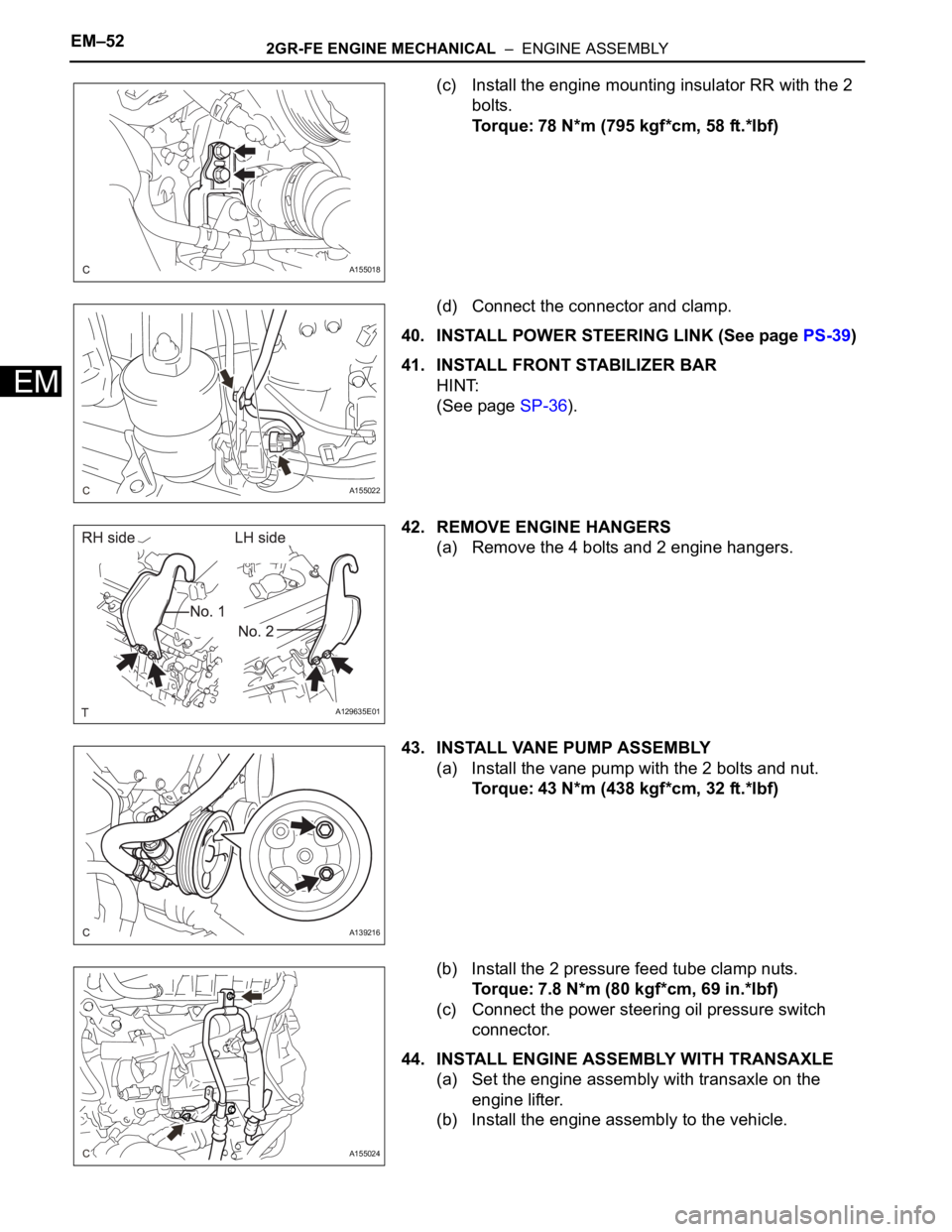
(c) Install the engine mounting insulator RR with the 2
bolts.
Torque: 78 N*m (795 kgf*cm, 58 ft.*lbf)
(d) Connect the connector and clamp.
40. INSTALL POWER STEERING LINK (See page PS-39)
41. INSTALL FRONT STABILIZER BAR
HINT:
(See page SP-36).
42. REMOVE ENGINE HANGERS
(a) Remove the 4 bolts and 2 engine hangers.
43. INSTALL VANE PUMP ASSEMBLY
(a) Install the vane pump with the 2 bolts and nut.
Torque: 43 N*m (438 kgf*cm, 32 ft.*lbf)
(b) Install the 2 pressure feed tube clamp nuts.
Torque: 7.8 N*m (80 kgf*cm, 69 in.*lbf)
(c) Connect the power steering oil pressure switch
connector.
44. INSTALL ENGINE ASSEMBLY WITH TRANSAXLE
(a) Set the engine assembly with transaxle on the
engine lifter.
(b) Install the engine assembly to the vehicle.
A155018
A155022
A129635E01
A139216
A155024
Page 870 of 3000
2GR-FE ENGINE MECHANICAL – ENGINE ASSEMBLYEM–53
EM
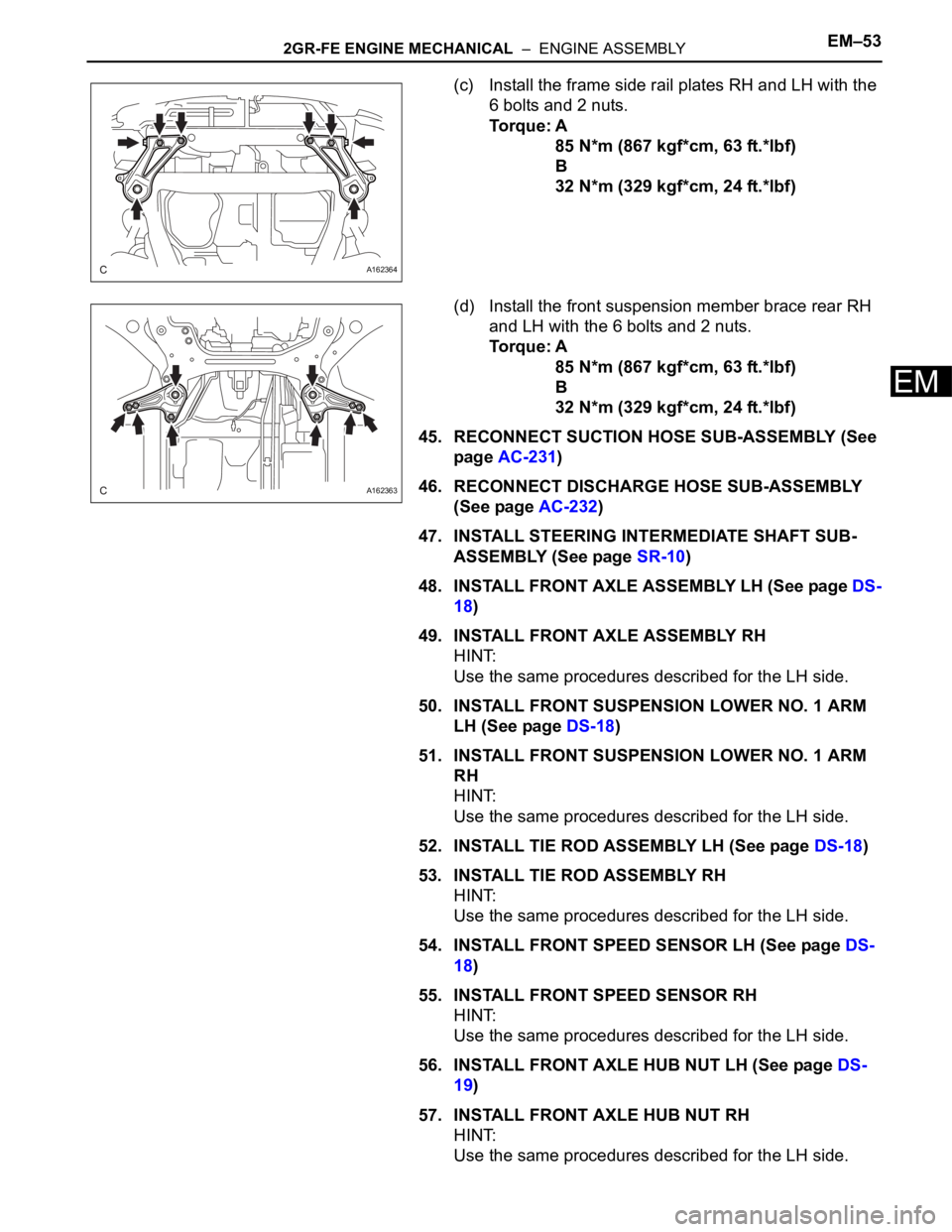
(c) Install the frame side rail plates RH and LH with the
6 bolts and 2 nuts.
Torque: A
85 N*m (867 kgf*cm, 63 ft.*lbf)
B
32 N*m (329 kgf*cm, 24 ft.*lbf)
(d) Install the front suspension member brace rear RH
and LH with the 6 bolts and 2 nuts.
Torque: A
85 N*m (867 kgf*cm, 63 ft.*lbf)
B
32 N*m (329 kgf*cm, 24 ft.*lbf)
45. RECONNECT SUCTION HOSE SUB-ASSEMBLY (See
page AC-231)
46. RECONNECT DISCHARGE HOSE SUB-ASSEMBLY
(See page AC-232)
47. INSTALL STEERING INTERMEDIATE SHAFT SUB-
ASSEMBLY (See page SR-10)
48. INSTALL FRONT AXLE ASSEMBLY LH (See page DS-
18)
49. INSTALL FRONT AXLE ASSEMBLY RH
HINT:
Use the same procedures described for the LH side.
50. INSTALL FRONT SUSPENSION LOWER NO. 1 ARM
LH (See page DS-18)
51. INSTALL FRONT SUSPENSION LOWER NO. 1 ARM
RH
HINT:
Use the same procedures described for the LH side.
52. INSTALL TIE ROD ASSEMBLY LH (See page DS-18)
53. INSTALL TIE ROD ASSEMBLY RH
HINT:
Use the same procedures described for the LH side.
54. INSTALL FRONT SPEED SENSOR LH (See page DS-
18)
55. INSTALL FRONT SPEED SENSOR RH
HINT:
Use the same procedures described for the LH side.
56. INSTALL FRONT AXLE HUB NUT LH (See page DS-
19)
57. INSTALL FRONT AXLE HUB NUT RH
HINT:
Use the same procedures described for the LH side.
A162364
A162363
Page 879 of 3000
EM–622GR-FE ENGINE MECHANICAL – ENGINE ASSEMBLY
EM
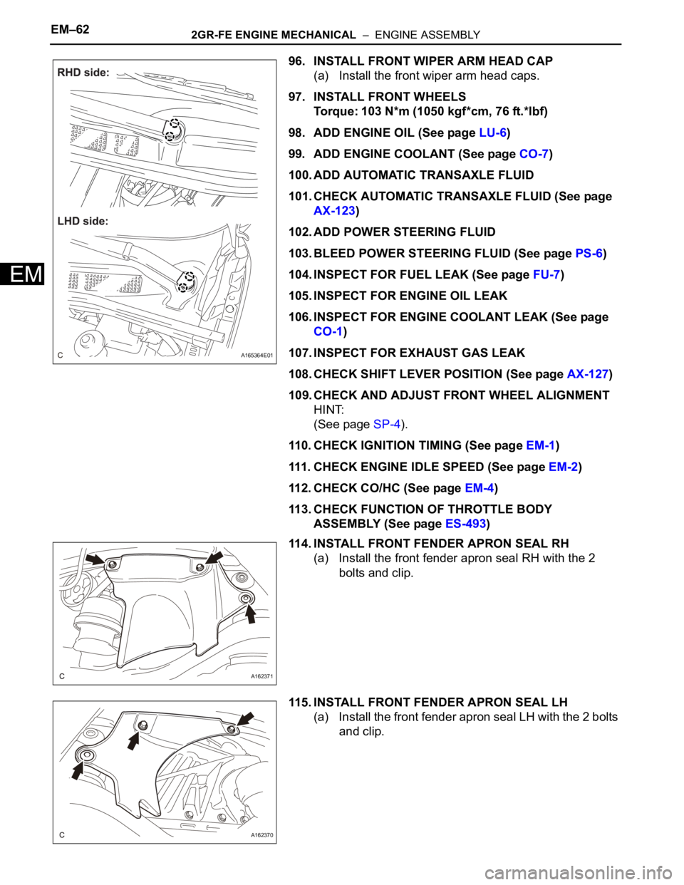
96. INSTALL FRONT WIPER ARM HEAD CAP
(a) Install the front wiper arm head caps.
97. INSTALL FRONT WHEELS
Torque: 103 N*m (1050 kgf*cm, 76 ft.*lbf)
98. ADD ENGINE OIL (See page LU-6)
99. ADD ENGINE COOLANT (See page CO-7)
100. ADD AUTOMATIC TRANSAXLE FLUID
101. CHECK AUTOMATIC TRANSAXLE FLUID (See page
AX-123)
102. ADD POWER STEERING FLUID
103. BLEED POWER STEERING FLUID (See page PS-6)
104. INSPECT FOR FUEL LEAK (See page FU-7)
105. INSPECT FOR ENGINE OIL LEAK
106. INSPECT FOR ENGINE COOLANT LEAK (See page
CO-1)
107. INSPECT FOR EXHAUST GAS LEAK
108. CHECK SHIFT LEVER POSITION (See page AX-127)
109. CHECK AND ADJUST FRONT WHEEL ALIGNMENT
HINT:
(See page SP-4).
110. CHECK IGNITION TIMING (See page EM-1)
111. CHECK ENGINE IDLE SPEED (See page EM-2)
112. CHECK CO/HC (See page EM-4)
113. CHECK FUNCTION OF THROTTLE BODY
ASSEMBLY (See page ES-493)
114. INSTALL FRONT FENDER APRON SEAL RH
(a) Install the front fender apron seal RH with the 2
bolts and clip.
115. INSTALL FRONT FENDER APRON SEAL LH
(a) Install the front fender apron seal LH with the 2 bolts
and clip.
A165364E01
A162371
A162370
Page 991 of 3000
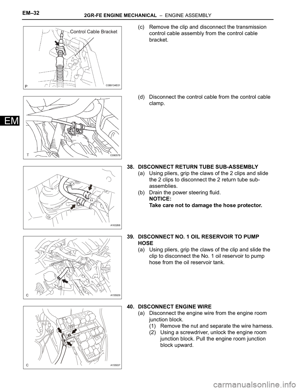
EM–322GR-FE ENGINE MECHANICAL – ENGINE ASSEMBLY
EM
(c) Remove the clip and disconnect the transmission
control cable assembly from the control cable
bracket.
(d) Disconnect the control cable from the control cable
clamp.
38. DISCONNECT RETURN TUBE SUB-ASSEMBLY
(a) Using pliers, grip the claws of the 2 clips and slide
the 2 clips to disconnect the 2 return tube sub-
assemblies.
(b) Drain the power steering fluid.
NOTICE:
Take care not to damage the hose protector.
39. DISCONNECT NO. 1 OIL RESERVOIR TO PUMP
HOSE
(a) Using pliers, grip the claws of the clip and slide the
clip to disconnect the No. 1 oil reservoir to pump
hose from the oil reservoir tank.
40. DISCONNECT ENGINE WIRE
(a) Disconnect the engine wire from the engine room
junction block.
(1) Remove the nut and separate the wire harness.
(2) Using a screwdriver, unlock the engine room
junction block. Pull the engine room junction
block upward.
C089134E01
C090579
A163268
A155029
A155037
Page 993 of 3000
EM–342GR-FE ENGINE MECHANICAL – ENGINE ASSEMBLY
EM
45. REMOVE PROPELLER WITH CENTER BEARING
SHAFT ASSEMBLY (See page PR-3)
46. DISCONNECT FRONT STABILIZER LINK ASSEMBLY
LH (See page DS-5)
47. DISCONNECT FRONT STABILIZER LINK ASSEMBLY
RH
HINT:
Use the same procedures described for the LH side.
48. REMOVE FRONT AXLE HUB NUT LH (See page DS-
5)
49. REMOVE FRONT AXLE HUB NUT RH
HINT:
Use the same procedures described for the LH side.
50. DISCONNECT FRONT SPEED SENSOR LH (See page
DS-5)
51. DISCONNECT FRONT SPEED SENSOR RH
HINT:
Use the same procedures described for the LH side.
52. DISCONNECT TIE ROD ASSEMBLY LH (See page
DS-6)
53. DISCONNECT TIE ROD ASSEMBLY RH
HINT:
Use the same procedures described for the LH side.
54. SEPARATE FRONT SUSPENSION LOWER NO. 1
ARM LH (See page DS-6)
55. SEPARATE FRONT SUSPENSION LOWER NO. 1
ARM RH
HINT:
Use the same procedures described for the LH side.
56. SEPARATE FRONT AXLE ASSEMBLY LH (See page
DS-6)
57. SEPARATE FRONT AXLE ASSEMBLY RH
HINT:
Use the same procedures described for the LH side.
58. DISCONNECT STEERING INTERMEDIATE SHAFT
SUB-ASSEMBLY
59. DISCONNECT DISCHARGE HOSE SUB-ASSEMBLY
(See page AC-227)
60. DISCONNECT SUCTION HOSE SUB-ASSEMBLY (See
page AC-227)
61. REMOVE ENGINE ASSEMBLY WITH TRANSAXLE
(a) Set the engine lifter.