2007 TOYOTA SIENNA ad blue
[x] Cancel search: ad bluePage 55 of 3000
INTRODUCTION – HOW TO TROUBLESHOOT ECU CONTROLLED SYSTEMSIN–43
IN
(d) HIGH ELECTRICAL LOAD METHOD: When a
malfunction seems to occur when electrical load is
excessive.
(1) Turn on the heater blower, headlight, rear
window defogger and all other electrical loads.
Check if the malfunction reoccurs.
5. DIAGNOSTIC TROUBLE CODE CHART
Look for output Diagnostic Trouble Codes (DTCs) (from the
DTC checks) in the appropriate section's Diagnostic Trouble
Code Chart. Use the chart to determine the trouble area and
the proper inspection procedure. A description of each of the
chart's columns is shown in the table below.
6. PROBLEM SYMPTOMS TABLE
When a "Normal" code is output during a DTC check but
the problem still occurs, use the Problem Symptoms
Table. The suspected areas (circuits or parts) for each
problem symptoms are in the table. The suspected areas
are listed in order of probability. A description of each of
the chart's columns is shown in the table below.
HINT:
In some cases, the problem is not detected by the
diagnostic system even though a problem symptom
occurs. It is possible that the problem is occurring
outside the detection range of the diagnostic system, or
that the problem occurs in a completely different system.
7. CIRCUIT INSPECTION
A description of the main areas of each circuit inspection
is shown in the table below.
B107149
Item Description
DTC No. Indicates the diagnostic trouble code
Detection Item Indicates the system or details of the problem
Trouble Area Indicates the suspect areas of the problem
See Page Indicates the page where the inspection procedures for each circuit is
to be found, or gives instruction for checking and repairs.
Item Description
Problem Symptom -
Circuit Inspection, Inspection Order Indicates the order in which the circuits need to be checked
Circuit or Part Name Indicates the circuit or part which needs to be checked
See Page Indicates the page where the flowchart for each circuit is located
Item Description
Circuit Description The major role, operation of the circuit and its component parts are
explained.
Diagnostic Trouble Code No. and Detection item Indicates the diagnostic trouble codes, diagnostic trouble code
settings and suspected areas for a problem
Wiring diagram This shows a wiring diagram of the circuit.
Use this diagram together with ELECTRICAL WIRING DIAGRAM to
thoroughly understand the circuit.
Wire colors are indicated by an alphabetical code. B = Black, L = Blue,
R = Red, BR = Brown, LG = Light Green, V = Violet, G = Green, O =
Orange, W = White, GR = Gray, P = Pink, Y = Yellow, SB = Sky Blue
The first letter indicates the basic wire color and the second letter
indicates the color of the stripe.
Page 73 of 3000
INTRODUCTION – HOW TO TROUBLESHOOT ECU CONTROLLED SYSTEMSIN–43
IN
(d) HIGH ELECTRICAL LOAD METHOD: When a
malfunction seems to occur when electrical load is
excessive.
(1) Turn on the heater blower, headlight, rear
window defogger and all other electrical loads.
Check if the malfunction reoccurs.
5. DIAGNOSTIC TROUBLE CODE CHART
Look for output Diagnostic Trouble Codes (DTCs) (from the
DTC checks) in the appropriate section's Diagnostic Trouble
Code Chart. Use the chart to determine the trouble area and
the proper inspection procedure. A description of each of the
chart's columns is shown in the table below.
6. PROBLEM SYMPTOMS TABLE
When a "Normal" code is output during a DTC check but
the problem still occurs, use the Problem Symptoms
Table. The suspected areas (circuits or parts) for each
problem symptoms are in the table. The suspected areas
are listed in order of probability. A description of each of
the chart's columns is shown in the table below.
HINT:
In some cases, the problem is not detected by the
diagnostic system even though a problem symptom
occurs. It is possible that the problem is occurring
outside the detection range of the diagnostic system, or
that the problem occurs in a completely different system.
7. CIRCUIT INSPECTION
A description of the main areas of each circuit inspection
is shown in the table below.
B107149
Item Description
DTC No. Indicates the diagnostic trouble code
Detection Item Indicates the system or details of the problem
Trouble Area Indicates the suspect areas of the problem
See Page Indicates the page where the inspection procedures for each circuit is
to be found, or gives instruction for checking and repairs.
Item Description
Problem Symptom -
Circuit Inspection, Inspection Order Indicates the order in which the circuits need to be checked
Circuit or Part Name Indicates the circuit or part which needs to be checked
See Page Indicates the page where the flowchart for each circuit is located
Item Description
Circuit Description The major role, operation of the circuit and its component parts are
explained.
Diagnostic Trouble Code No. and Detection item Indicates the diagnostic trouble codes, diagnostic trouble code
settings and suspected areas for a problem
Wiring diagram This shows a wiring diagram of the circuit.
Use this diagram together with ELECTRICAL WIRING DIAGRAM to
thoroughly understand the circuit.
Wire colors are indicated by an alphabetical code. B = Black, L = Blue,
R = Red, BR = Brown, LG = Light Green, V = Violet, G = Green, O =
Orange, W = White, GR = Gray, P = Pink, Y = Yellow, SB = Sky Blue
The first letter indicates the basic wire color and the second letter
indicates the color of the stripe.
Page 276 of 3000

NAVIGATION – NAVIGATION SYSTEMNS–15
NS
9. Bluetooth outline
(a) Bluethooth is a trademark owned by Bluetooth SIG.
Inc.
(b) Bluetooth is a new wireless connection technology
that uses the 2.4 GHz frequency band. This makes
it possible to connect a cellular phone (Bluetooth
compatible phone
*1) to the radio and navigation
assembly (the Bluetooth system is built in), and use
the handsfree function of the cellular phone, even if
it is in a pocket or bag. As a result, it is not
necessary to use a connector attached directly to
the cellular phone.
*1: Some versions of Bluetooth compatible cellular
phones may not function.
HINT:
The communication performance of Bluetooth may
vary depending on obstructions or radio wave
conditions between communication devices,
electromagnetic radiation, communication device
sensitivity, or antenna capacity.
E100921
E121227E01
Page 916 of 3000
2GR-FE ENGINE MECHANICAL – ENGINE UNITEM–111
EM
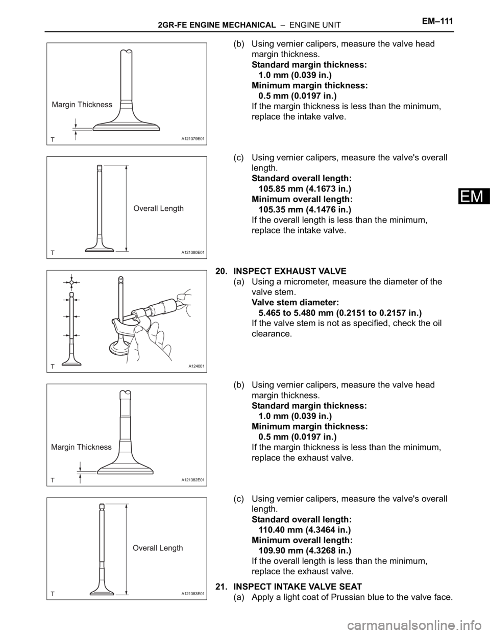
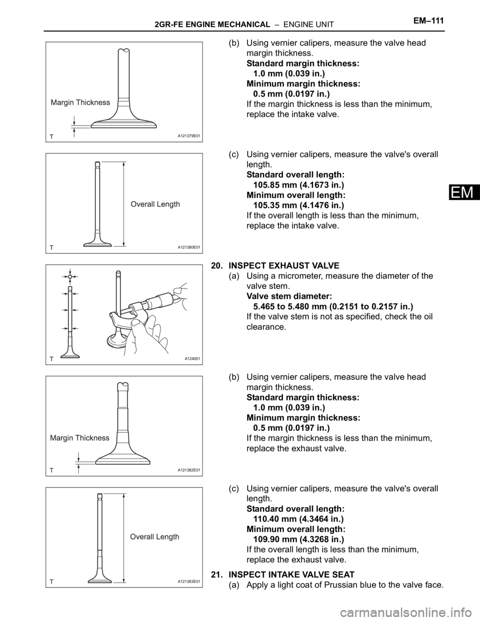
(b) Using vernier calipers, measure the valve head
margin thickness.
Standard margin thickness:
1.0 mm (0.039 in.)
Minimum margin thickness:
0.5 mm (0.0197 in.)
If the margin thickness is less than the minimum,
replace the intake valve.
(c) Using vernier calipers, measure the valve's overall
length.
Standard overall length:
105.85 mm (4.1673 in.)
Minimum overall length:
105.35 mm (4.1476 in.)
If the overall length is less than the minimum,
replace the intake valve.
20. INSPECT EXHAUST VALVE
(a) Using a micrometer, measure the diameter of the
valve stem.
Valve stem diameter:
5.465 to 5.480 mm (0.2151 to 0.2157 in.)
If the valve stem is not as specified, check the oil
clearance.
(b) Using vernier calipers, measure the valve head
margin thickness.
Standard margin thickness:
1.0 mm (0.039 in.)
Minimum margin thickness:
0.5 mm (0.0197 in.)
If the margin thickness is less than the minimum,
replace the exhaust valve.
(c) Using vernier calipers, measure the valve's overall
length.
Standard overall length:
110.40 mm (4.3464 in.)
Minimum overall length:
109.90 mm (4.3268 in.)
If the overall length is less than the minimum,
replace the exhaust valve.
21. INSPECT INTAKE VALVE SEAT
(a) Apply a light coat of Prussian blue to the valve face.
A121379E01
A121380E01
A124001
A121382E01
A121383E01
Page 917 of 3000
EM–1122GR-FE ENGINE MECHANICAL – ENGINE UNIT
EM
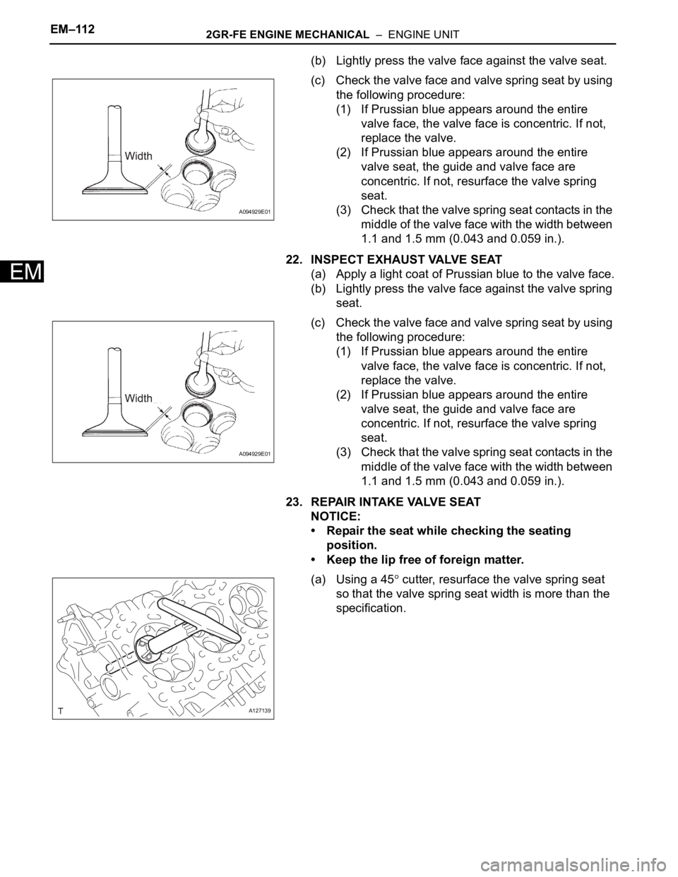
(b) Lightly press the valve face against the valve seat.
(c) Check the valve face and valve spring seat by using
the following procedure:
(1) If Prussian blue appears around the entire
valve face, the valve face is concentric. If not,
replace the valve.
(2) If Prussian blue appears around the entire
valve seat, the guide and valve face are
concentric. If not, resurface the valve spring
seat.
(3) Check that the valve spring seat contacts in the
middle of the valve face with the width between
1.1 and 1.5 mm (0.043 and 0.059 in.).
22. INSPECT EXHAUST VALVE SEAT
(a) Apply a light coat of Prussian blue to the valve face.
(b) Lightly press the valve face against the valve spring
seat.
(c) Check the valve face and valve spring seat by using
the following procedure:
(1) If Prussian blue appears around the entire
valve face, the valve face is concentric. If not,
replace the valve.
(2) If Prussian blue appears around the entire
valve seat, the guide and valve face are
concentric. If not, resurface the valve spring
seat.
(3) Check that the valve spring seat contacts in the
middle of the valve face with the width between
1.1 and 1.5 mm (0.043 and 0.059 in.).
23. REPAIR INTAKE VALVE SEAT
NOTICE:
• Repair the seat while checking the seating
position.
• Keep the lip free of foreign matter.
(a) Using a 45
cutter, resurface the valve spring seat
so that the valve spring seat width is more than the
specification.
A094929E01
A094929E01
A127139
Page 1058 of 3000
2GR-FE ENGINE MECHANICAL – ENGINE UNITEM–111
EM
(b) Using vernier calipers, measure the valve head
margin thickness.
Standard margin thickness:
1.0 mm (0.039 in.)
Minimum margin thickness:
0.5 mm (0.0197 in.)
If the margin thickness is less than the minimum,
replace the intake valve.
(c) Using vernier calipers, measure the valve's overall
length.
Standard overall length:
105.85 mm (4.1673 in.)
Minimum overall length:
105.35 mm (4.1476 in.)
If the overall length is less than the minimum,
replace the intake valve.
20. INSPECT EXHAUST VALVE
(a) Using a micrometer, measure the diameter of the
valve stem.
Valve stem diameter:
5.465 to 5.480 mm (0.2151 to 0.2157 in.)
If the valve stem is not as specified, check the oil
clearance.
(b) Using vernier calipers, measure the valve head
margin thickness.
Standard margin thickness:
1.0 mm (0.039 in.)
Minimum margin thickness:
0.5 mm (0.0197 in.)
If the margin thickness is less than the minimum,
replace the exhaust valve.
(c) Using vernier calipers, measure the valve's overall
length.
Standard overall length:
110.40 mm (4.3464 in.)
Minimum overall length:
109.90 mm (4.3268 in.)
If the overall length is less than the minimum,
replace the exhaust valve.
21. INSPECT INTAKE VALVE SEAT
(a) Apply a light coat of Prussian blue to the valve face.
A121379E01
A121380E01
A124001
A121382E01
A121383E01
Page 1059 of 3000
EM–1122GR-FE ENGINE MECHANICAL – ENGINE UNIT
EM
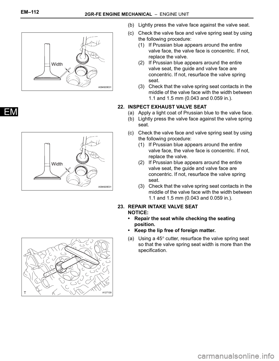
(b) Lightly press the valve face against the valve seat.
(c) Check the valve face and valve spring seat by using
the following procedure:
(1) If Prussian blue appears around the entire
valve face, the valve face is concentric. If not,
replace the valve.
(2) If Prussian blue appears around the entire
valve seat, the guide and valve face are
concentric. If not, resurface the valve spring
seat.
(3) Check that the valve spring seat contacts in the
middle of the valve face with the width between
1.1 and 1.5 mm (0.043 and 0.059 in.).
22. INSPECT EXHAUST VALVE SEAT
(a) Apply a light coat of Prussian blue to the valve face.
(b) Lightly press the valve face against the valve spring
seat.
(c) Check the valve face and valve spring seat by using
the following procedure:
(1) If Prussian blue appears around the entire
valve face, the valve face is concentric. If not,
replace the valve.
(2) If Prussian blue appears around the entire
valve seat, the guide and valve face are
concentric. If not, resurface the valve spring
seat.
(3) Check that the valve spring seat contacts in the
middle of the valve face with the width between
1.1 and 1.5 mm (0.043 and 0.059 in.).
23. REPAIR INTAKE VALVE SEAT
NOTICE:
• Repair the seat while checking the seating
position.
• Keep the lip free of foreign matter.
(a) Using a 45
cutter, resurface the valve spring seat
so that the valve spring seat width is more than the
specification.
A094929E01
A094929E01
A127139
Page 1606 of 3000
AX–220U151E AUTOMATIC TRANSAXLE – AUTOMATIC TRANSAXLE UNIT
AX
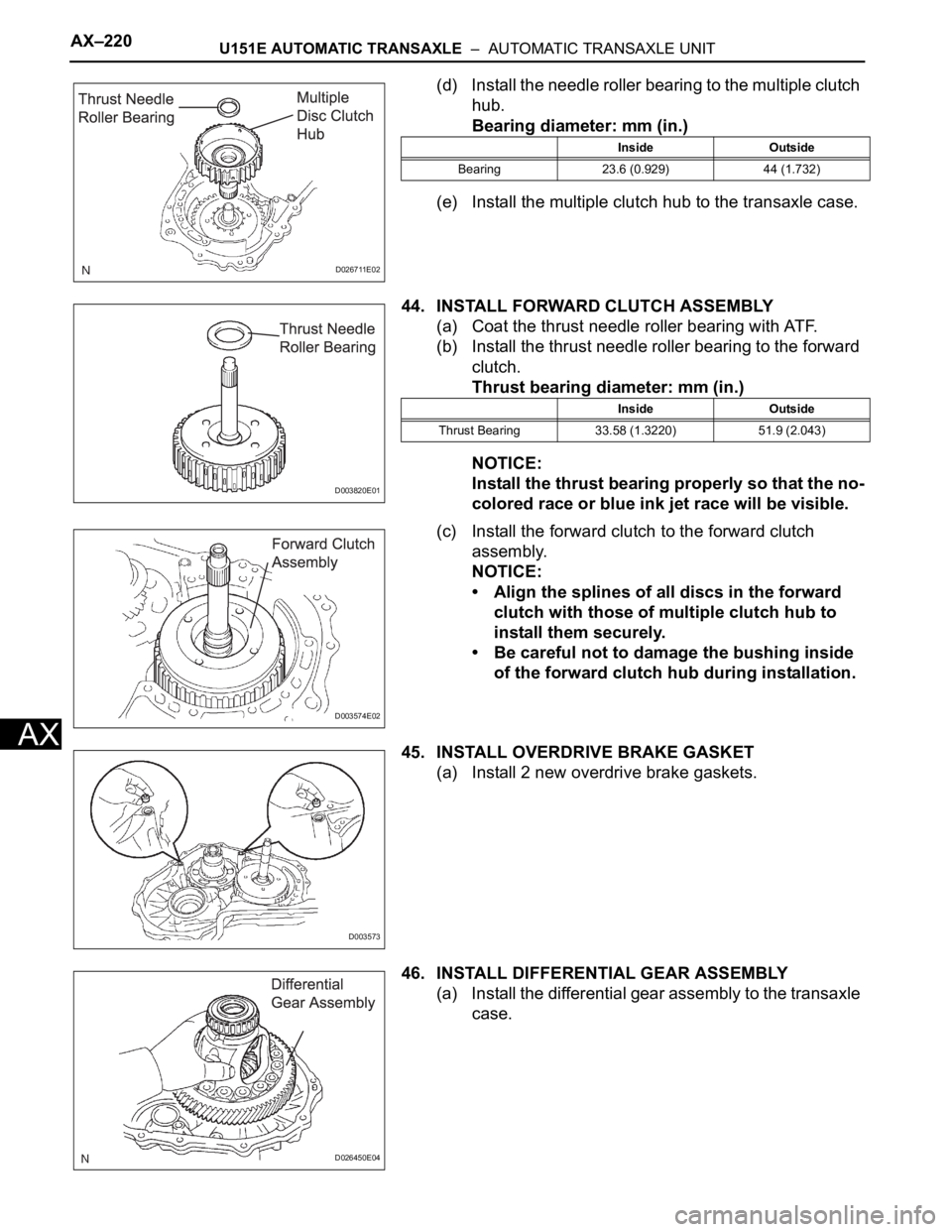
(d) Install the needle roller bearing to the multiple clutch
hub.
Bearing diameter: mm (in.)
(e) Install the multiple clutch hub to the transaxle case.
44. INSTALL FORWARD CLUTCH ASSEMBLY
(a) Coat the thrust needle roller bearing with ATF.
(b) Install the thrust needle roller bearing to the forward
clutch.
Thrust bearing diameter: mm (in.)
NOTICE:
Install the thrust bearing properly so that the no-
colored race or blue ink jet race will be visible.
(c) Install the forward clutch to the forward clutch
assembly.
NOTICE:
• Align the splines of all discs in the forward
clutch with those of multiple clutch hub to
install them securely.
• Be careful not to damage the bushing inside
of the forward clutch hub during installation.
45. INSTALL OVERDRIVE BRAKE GASKET
(a) Install 2 new overdrive brake gaskets.
46. INSTALL DIFFERENTIAL GEAR ASSEMBLY
(a) Install the differential gear assembly to the transaxle
case.
D026711E02
Inside Outside
Bearing 23.6 (0.929) 44 (1.732)
D003820E01
Inside Outside
Thrust Bearing 33.58 (1.3220) 51.9 (2.043)
D003574E02
D003573
D026450E04