2007 TOYOTA SIENNA cooling system
[x] Cancel search: cooling systemPage 75 of 3000
CO–42GR-FE COOLING – COOLING FAN SYSTEM
CO
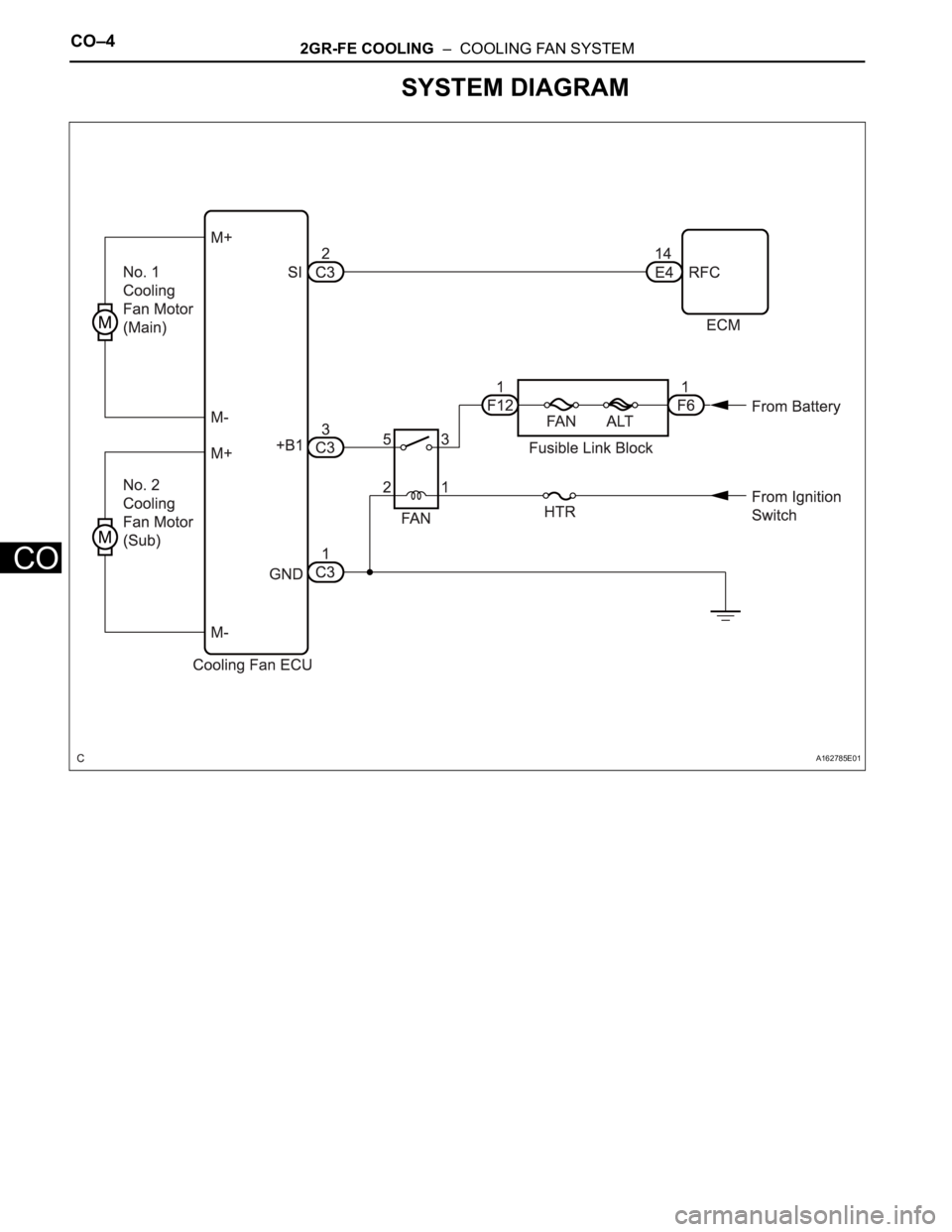
SYSTEM DIAGRAM
A162785E01
Page 76 of 3000

2GR-FE COOLING – COOLING FAN SYSTEMCO–5
CO
ON-VEHICLE INSPECTION
1. INSPECT COOLING FAN SYSTEM
(a) Put the vehicle in the following conditions:
(1) The engine switch is off.
(2) The coolant temperature is less than 95
C
(203
F).
(3) The battery voltage is between 9 and 14 V.
(4) The A/C switch is OFF.
(b) Clamp the 400 A probe of an ammeter over the M+
wire of each cooling fan motor.
(c) Turn the ignition switch to the ON position and wait
for approximately 10 seconds. Check that the fan
stops.
(d) Start the engine. Check that the fan stops with the
engine idling.
HINT:
• Make sure that the radiator engine coolant
temperature is less than 95
C (203F).
• Turn the A/C switch OFF.
(e) Check that the fan operates when the A/C switch is
turned ON (MAX COOL and the magnetic clutch is
operating).
Standard current
HINT:
The coolant temperature is less than 95
C (203F).
(f) Check that the fan operates when the engine
coolant temperature sensor connector is
disconnected.
Standard current
Item Specified Condition
No. 1 cooling fan motor 5 to 14 A
No. 2 cooling fan motor 4 to 12 A
Item Specified Condition
No. 1 cooling fan motor 5 to 19 A
No. 2 cooling fan motor 4 to 16 A
Page 77 of 3000
CO–62GR-FE COOLING – COOLING FAN SYSTEM
CO
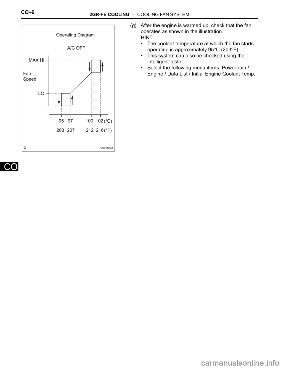
(g) After the engine is warmed up, check that the fan
operates as shown in the illustration.
HINT:
• The coolant temperature at which the fan starts
operating is approximately 95
C (203F).
• This system can also be checked using the
intelligent tester.
• Select the following menu items: Powertrain /
Engine / Data List / Initial Engine Coolant Temp.
A139339E05
Page 207 of 3000
AIR CONDITIONING – CONDENSERAC–237
AC
REMOVAL
1. RECOVER REFRIGERANT FROM REFRIGERATION
SYSTEM (See page AC-172)
2. REMOVE NO. 2 AIR CLEANER INLET (See page EM-
28)
3. REMOVE FRONT BUMPER ASSEMBLY (See page
ET-3)
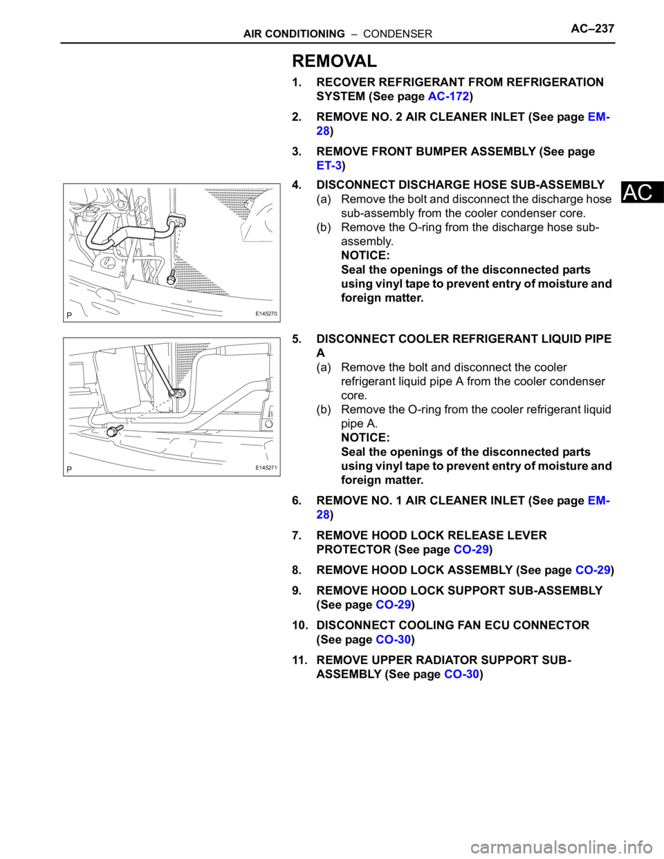
4. DISCONNECT DISCHARGE HOSE SUB-ASSEMBLY
(a) Remove the bolt and disconnect the discharge hose
sub-assembly from the cooler condenser core.
(b) Remove the O-ring from the discharge hose sub-
assembly.
NOTICE:
Seal the openings of the disconnected parts
using vinyl tape to prevent entry of moisture and
foreign matter.
5. DISCONNECT COOLER REFRIGERANT LIQUID PIPE
A
(a) Remove the bolt and disconnect the cooler
refrigerant liquid pipe A from the cooler condenser
core.
(b) Remove the O-ring from the cooler refrigerant liquid
pipe A.
NOTICE:
Seal the openings of the disconnected parts
using vinyl tape to prevent entry of moisture and
foreign matter.
6. REMOVE NO. 1 AIR CLEANER INLET (See page EM-
28)
7. REMOVE HOOD LOCK RELEASE LEVER
PROTECTOR (See page CO-29)
8. REMOVE HOOD LOCK ASSEMBLY (See page CO-29)
9. REMOVE HOOD LOCK SUPPORT SUB-ASSEMBLY
(See page CO-29)
10. DISCONNECT COOLING FAN ECU CONNECTOR
(See page CO-30)
11. REMOVE UPPER RADIATOR SUPPORT SUB-
ASSEMBLY (See page CO-30)
E145270
E145271
Page 318 of 3000

2GR-FE ENGINE CONTROL SYSTEM – SFI SYSTEMES–1
ES
SFI SYSTEM
PRECAUTION
1. INITIALIZATION
NOTICE:
• Perform RESET MEMORY (AT initialization) when
replacing the automatic transaxle assembly, engine
assembly or ECM (See page AX-16).
• Perform REGISTRATION (VIN registration) when
replacing the ECM (See page ES-15).
HINT:
Initialization cannot be completed by only removing the
battery.
2. FOR USING INTELLIGENT TESTER
CAUTION:
Observe the following items for safety reasons:
• Before using the tester, read the instruction
manual.
• Prevent the tester cable from being caught on the
pedals, shift lever and steering wheel when
driving with the tester connected to the vehicle.
• When driving the vehicle for testing purposes
using the tester, two persons are required. One is
for driving the vehicle, and the other operates the
tester.
3. FOR USING BATTERY DURING INSPECTION
(a) While using the battery during inspection, do not
bring the positive and negative tester probes too
close to each other as a short circuit may occur.
4. COOLING FAN SYSTEM
NOTICE:
• When the ignition switch is turned off and the engine
temperature is high, the cooling fans may operate for
approximately 3 minutes.
• After turning the ignition switch off, keep hands and
objects away from the fans when they are operating.
HINT:
If all of the following are met for a certain period of time during
a few minute period immediately before the engine is
stopped, the electric fans will continue to operate for 3
minutes after the engine is stopped. This is performed to
ensure restartability and stabilize idle speed.
– The intelligent tester indicates a very high coolant
temperature.
– The intelligent tester indicates a high outside air
temperature.
– The vehicle has been driven under high load (driving on an
uphill or equivalent).
The following sensors are used for this control:
– Coolant temperature sensor
– Outside air temperature sensor
–MAF sensor
– Vehicle speed sensors
Page 357 of 3000

2GR-FE ENGINE CONTROL SYSTEM – SFI SYSTEMES–31
ES
PROBLEM SYMPTOMS TABLE
HINT:
When a malfunction is not confirmed by a DTC (Diagnostic
Trouble Code) check and the cause of problem cannot be
identified through a basic inspection, troubleshoot according
to the priority order indicated in the table below.
SFI SYSTEM
Symptom Suspected Area See page
Engine does not crank (does not start)1. Immobilizer systemEI-2
2. StarterST-7
3. STARTER RelayST-14
4. Cranking holding function circuitES-461
No initial combustion (does not start)1. ECM power source circuitES-437
2. Ignition systemIG-5
3. Fuel pump control circuitES-451
4. InjectorFU-16
5. VC output circuitES-444
6. ECMES-498
Difficult to start (engine cranks normally)1. Electronic Throttle Control System (ETCS)ES-329
2. Fuel pump control circuitES-451
3. Ignition systemIG-5
4. Spark plugIG-7
5. CompressionEM-3
6. InjectorFU-16
7. VC output circuitES-444
Difficult to start with cold engine1. Cranking holding function circuitES-461
2. Electronic Throttle Control System (ETCS)ES-329
3. Fuel pump control circuitES-451
4. Spark plugIG-7
5. Ignition systemIG-6
6. InjectorFU-16
7. Engine coolant temperature sensorES-516
Difficult to start with hot engine1. Cooling fan systemCO-4
2. Cranking holding function circuitES-461
3. Electronic Throttle Control System (ETCS)ES-329
4. Fuel pump control circuitES-451
5. Spark plugIG-7
6. Ignition systemIG-5
7. InjectorFU-16
8. Engine coolant temperature sensorES-516
High engine idle speed (poor idling)1. Electronic Throttle Control System (ETCS)ES-329
2. ECM power source circuitES-437
3. A/C signal circuit (Compressor circuit) -
4. Acoustic Control Induction System (ACIS)ES-470
5. PCV hoseEC-15
6. ECMES-498
Page 374 of 3000
ES–682GR-FE ENGINE CONTROL SYSTEM – SFI SYSTEM
ES
P0125 Insufficient Coolant
Temperature for
Closed Loop Fuel
Control1. Cooling system
2. Engine coolant
temperature sensor
3. ThermostatComes on DTC storedES-154
P0128 Coolant Thermostat
(Coolant
Temperature Below
Thermostat
Regulating
Temperature)1. Thermostat
2. Cooling system
3. ECT sensor
4. ECMComes on DTC storedES-157
P0136 Oxygen Sensor
Circuit Malfunction
(Bank 1 Sensor 2)1. Open or short in
HO2 sensor (bank 1,
2 sensor 2) circuit
2. HO2 sensor (bank
1, 2 sensor 2)
3. HO2 sensor heater
(bank 1, 2 sensor 2)
4. Air-Fuel Ratio (A/
F) sensor (bank 1, 2
sensor 1)
5. EFI relay
6. Gas leakage from
exhaust systemComes on DTC storedES-160
P0137 Oxygen Sensor
Circuit Low Voltage
(Bank 1 Sensor 2)1. Open in HO2
sensor (bank 1, 2
sensor 2) circuit
2. HO2 sensor (bank
1, 2 sensor 2)
3. HO2 sensor heater
(bank 1, 2 sensor 2)
4. EFI relay
5. Gas leakage from
exhaust systemComes on DTC storedES-160
P0138 Oxygen Sensor
Circuit High Voltage
(Bank 1 Sensor 2)1. Short in HO2
sensor (bank 1, 2
sensor 2) circuit
2. HO2 sensor (bank
1, 2 sensor 2)
3. ECM internal
circuit malfunction
4. Air-Fuel ratio (A/F)
sensor (bank 1, 2
sensor 1)Comes on DTC storedES-160
P0141 Oxygen Sensor
Heater Circuit
Malfunction (Bank 1
Sensor 2)1. HO2 sensor
2. ECMComes on DTC storedES-109
P0156 Oxygen Sensor
Circuit Malfunction
(Bank 2 Sensor 2)1. Open or short in
HO2 sensor (bank 1,
2 sensor 2) circuit
2. HO2 sensor (bank
1, 2 sensor 2)
3. HO2 sensor heater
(bank 1, 2 sensor 2)
4. Air-Fuel Ratio (A/
F) sensor (bank 1, 2
sensor 1)
5. EFI relay
6. Gas leakage from
exhaust systemComes on DTC storedES-160 DTC Code Detection Item Suspected Trouble
AreaMIL Memory See page
Page 468 of 3000

ES–1622GR-FE ENGINE CONTROL SYSTEM – SFI SYSTEM
ES
DESCRIPTION
Refer to DTC P0115 (See page ES-133).
MONITOR DESCRIPTION
The resistance of the ECT sensor varies in proportion to the actual ECT. The ECM supplies a constant
voltage to the sensor and monitors the signal output voltage of the sensor. The signal voltage output
varies according to the changing resistance of the sensor. After the engine is started, the ECT is
monitored through this signal. If the ECT sensor indicates that the engine is not yet warm enough for
closed-loop fuel control, despite a specified period of time having elapsed since the engine was started,
the ECM interprets this as a malfunction in the sensor or cooling system and sets the DTC.
Example:
The ECT is 0
C (32F) at engine start. After 5 minutes running time, the ECT sensor still indicates that the
engine is not warm enough to begin closed-loop fuel (air-fuel ratio feedback) control. The ECM interprets
this as a malfunction in the sensor or cooling system and sets the DTC.
MONITOR STRATEGY
TYPICAL ENABLING CONDITIONS
TYPICAL MALFUNCTION THRESHOLDS
WIRING DIAGRAM
Refer to DTC P0115 (See page ES-134).
DTC P0125Insufficient Coolant Temperature for Closed
Loop Fuel Control
DTC No. DTC Detection Condition Trouble Area
P0125Engine coolant temperature (ECT) does not reach
closed-loop enabling temperature for 20 minutes (this
period varies with engine start ECT)• Cooling system
• Engine coolant temperature sensor
• Thermostat
Related DTCs P0125: Insufficient engine coolant temperature for closed-loop fuel control
Required Sensors / Components (Main) Thermostat, cooling system
Required Sensors / Components (Related) Engine coolant temperature sensor and mass air flow meter
Frequency of Operation Continuous
Duration78 seconds: Engine coolant temperature at engine start -8.34
C (17F) or more
131.3 seconds: Engine coolant temperature at engine start -19.45 to -8.34C (-3 to
17
F)
20 minutes: Engine coolant temperature at engine start less than -19.45
C (-3F)
MIL Operation 2 driving cycles
Sequence of Operation None
The monitor will run whenever these DTCs are not
presentP0100, P0101, P0102, P0103 (MAF) sensor, P0110, P0111, P0112, P0113 (IAT
sensor), P0115, P0116, P0117, P0118 (ECT sensor)
Fuel cut OFF
Engine Running
Time until actual engine coolant temperature reaches
closed-loop fuel control enabling temperature78 seconds or more: Engine coolant temperature at engine start -8.34
C (17F) or
more
131.3 seconds or more: Engine coolant temperature at engine start -19.45 to -8.34
C
(-3 to 17
F)
20 minutes or more: Engine coolant temperature at engine start less than -19.45C (-
3
F)