2007 TOYOTA SIENNA warning lights
[x] Cancel search: warning lightsPage 236 of 3000

THEFT DETERRENT – THEFT DETERRENT SYSTEMTD–3
TD
SYSTEM DESCRIPTION
1. OUTLINE OF THEFT DETERRENT SYSTEM
(a) When the theft deterrent system detects that the
vehicle is being tampered with, the system sets off
the alarm, causing the horns to sound and the lights
to light up or blink in order to alert people around the
vehicle to the theft.
(b) The theft deterrent system has 2 modes; one is the
active arming mode (see ACTIVE ARMING MODE)
and the other is passive arming mode (see
PASSIVE ARMING MODE). The passive arming
mode can be switched ON/OFF using the specified
method.
(c) Each mode has 4 states; a disarmed state, an
arming preparation state, an armed state and an
alarm sounding state.
(1) Disarmed state:
• The alarm function is not operating.
• The theft deterrent system is not operating.
(2) Arming preparation state:
• The time until the system goes into the armed
state.
• The theft deterrent system is not operating.
(3) Armed state:
• The theft deterrent system is operating.
(4) Alarm sounding state:
• Alarm function is operating.
Alarm time:
Approx. 60 sec.
Refer to table below for alarm method and time:
HINT:
If any of the doors are unlocked with no key in
the ignition key cylinder during the armed state,
a forced door lock signal will be output (see
FORCED DOOR LOCK CONTROL).
2. ACTIVE ARMING MODE
HINT:
• Active arming mode starts the alarm control
immediately after the doors are locked.
• This system activates as described in the diagram
below when one of items for each condition is met.
Alarm MethodHeadlight Blinking (approx. 0.4 second cycles)
Taillight Blinking (approx. 0.4 second cycles)
Hazard Warning Light Blinking (cycles of flasher relay)
Interior Light Illuminating
Vehicle HornSounding
(approx. 0.4 second cycles)
Security HornSounding
(approx. 0.4 second cycles)
Alarm Time Approx. 60 sec.
Page 1342 of 3000
2GR-FE CHARGING – CHARGING SYSTEMCH–7
CH
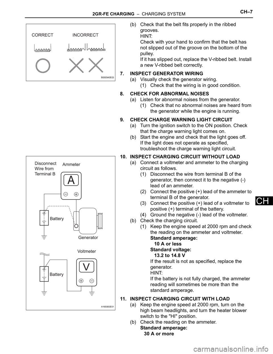
(b) Check that the belt fits properly in the ribbed
grooves.
HINT:
Check with your hand to confirm that the belt has
not slipped out of the groove on the bottom of the
pulley.
If it has slipped out, replace the V-ribbed belt. Install
a new V-ribbed belt correctly.
7. INSPECT GENERATOR WIRING
(a) Visually check the generator wiring.
(1) Check that the wiring is in good condition.
8. CHECK FOR ABNORMAL NOISES
(a) Listen for abnormal noises from the generator.
(1) Check that no abnormal noises are heard from
the generator while the engine is running.
9. CHECK CHARGE WARNING LIGHT CIRCUIT
(a) Turn the ignition switch to the ON position. Check
that the charge warning light comes on.
(b) Start the engine and check that the light goes off.
If the light does not operate as specified,
troubleshoot the charge warning light circuit.
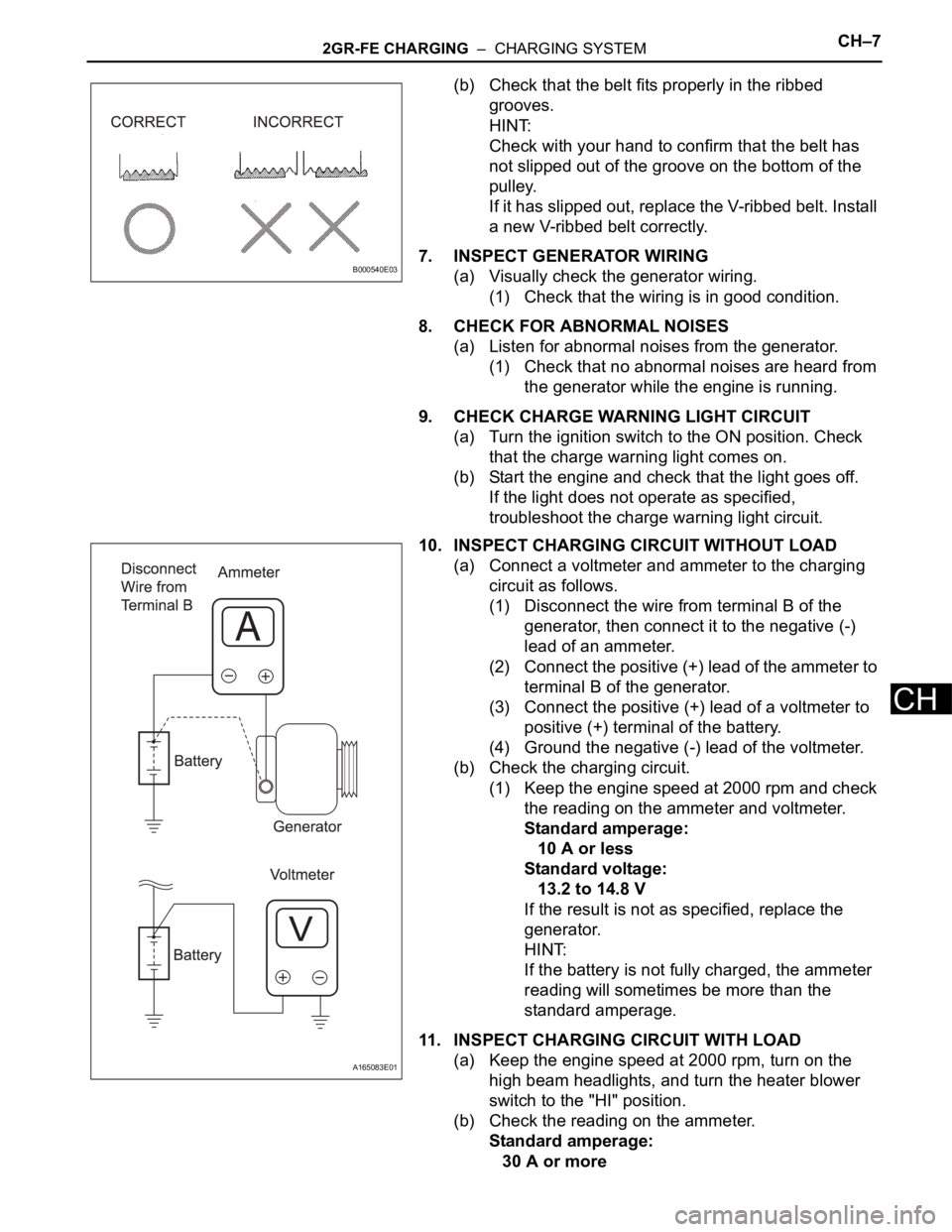
10. INSPECT CHARGING CIRCUIT WITHOUT LOAD
(a) Connect a voltmeter and ammeter to the charging
circuit as follows.
(1) Disconnect the wire from terminal B of the
generator, then connect it to the negative (-)
lead of an ammeter.
(2) Connect the positive (+) lead of the ammeter to
terminal B of the generator.
(3) Connect the positive (+) lead of a voltmeter to
positive (+) terminal of the battery.
(4) Ground the negative (-) lead of the voltmeter.
(b) Check the charging circuit.
(1) Keep the engine speed at 2000 rpm and check
the reading on the ammeter and voltmeter.
Standard amperage:
10 A or less
Standard voltage:
13.2 to 14.8 V
If the result is not as specified, replace the
generator.
HINT:
If the battery is not fully charged, the ammeter
reading will sometimes be more than the
standard amperage.
11. INSPECT CHARGING CIRCUIT WITH LOAD
(a) Keep the engine speed at 2000 rpm, turn on the
high beam headlights, and turn the heater blower
switch to the "HI" position.
(b) Check the reading on the ammeter.
Standard amperage:
30 A or more
B000540E03
A165083E01
Page 1347 of 3000
2GR-FE CHARGING – CHARGING SYSTEMCH–7
CH
(b) Check that the belt fits properly in the ribbed
grooves.
HINT:
Check with your hand to confirm that the belt has
not slipped out of the groove on the bottom of the
pulley.
If it has slipped out, replace the V-ribbed belt. Install
a new V-ribbed belt correctly.
7. INSPECT GENERATOR WIRING
(a) Visually check the generator wiring.
(1) Check that the wiring is in good condition.
8. CHECK FOR ABNORMAL NOISES
(a) Listen for abnormal noises from the generator.
(1) Check that no abnormal noises are heard from
the generator while the engine is running.
9. CHECK CHARGE WARNING LIGHT CIRCUIT
(a) Turn the ignition switch to the ON position. Check
that the charge warning light comes on.
(b) Start the engine and check that the light goes off.
If the light does not operate as specified,
troubleshoot the charge warning light circuit.
10. INSPECT CHARGING CIRCUIT WITHOUT LOAD
(a) Connect a voltmeter and ammeter to the charging
circuit as follows.
(1) Disconnect the wire from terminal B of the
generator, then connect it to the negative (-)
lead of an ammeter.
(2) Connect the positive (+) lead of the ammeter to
terminal B of the generator.
(3) Connect the positive (+) lead of a voltmeter to
positive (+) terminal of the battery.
(4) Ground the negative (-) lead of the voltmeter.
(b) Check the charging circuit.
(1) Keep the engine speed at 2000 rpm and check
the reading on the ammeter and voltmeter.
Standard amperage:
10 A or less
Standard voltage:
13.2 to 14.8 V
If the result is not as specified, replace the
generator.
HINT:
If the battery is not fully charged, the ammeter
reading will sometimes be more than the
standard amperage.
11. INSPECT CHARGING CIRCUIT WITH LOAD
(a) Keep the engine speed at 2000 rpm, turn on the
high beam headlights, and turn the heater blower
switch to the "HI" position.
(b) Check the reading on the ammeter.
Standard amperage:
30 A or more
B000540E03
A165083E01
Page 2362 of 3000
BRAKE CONTROL – ANTI-LOCK BRAKE SYSTEMBC–11
BC
DIAGNOSIS SYSTEM
1. DESCRIPTION
(a) Release the parking brake pedal.
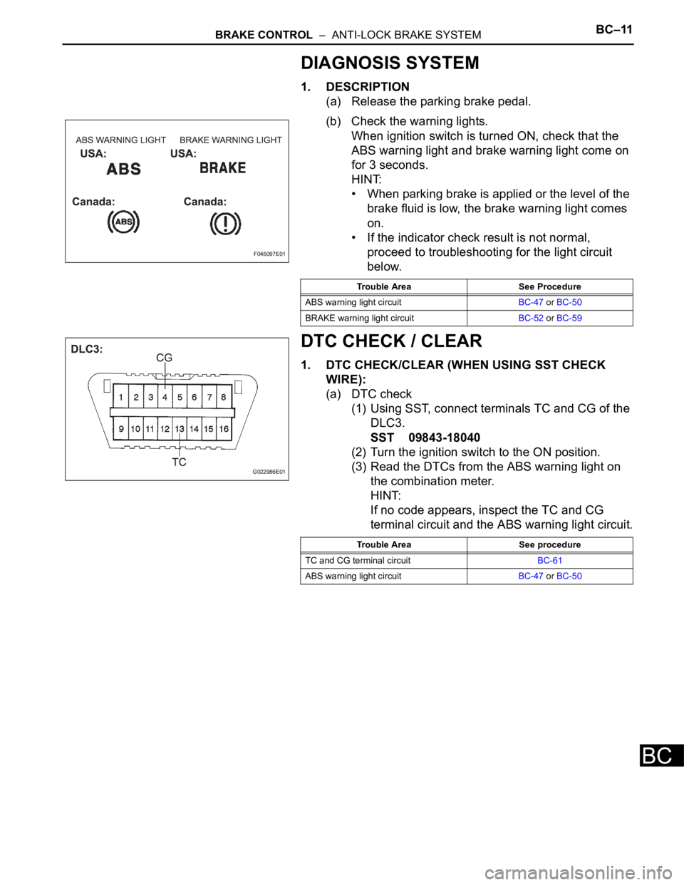
(b) Check the warning lights.
When ignition switch is turned ON, check that the
ABS warning light and brake warning light come on
for 3 seconds.
HINT:
• When parking brake is applied or the level of the
brake fluid is low, the brake warning light comes
on.
• If the indicator check result is not normal,
proceed to troubleshooting for the light circuit
below.
DTC CHECK / CLEAR
1. DTC CHECK/CLEAR (WHEN USING SST CHECK
WIRE):
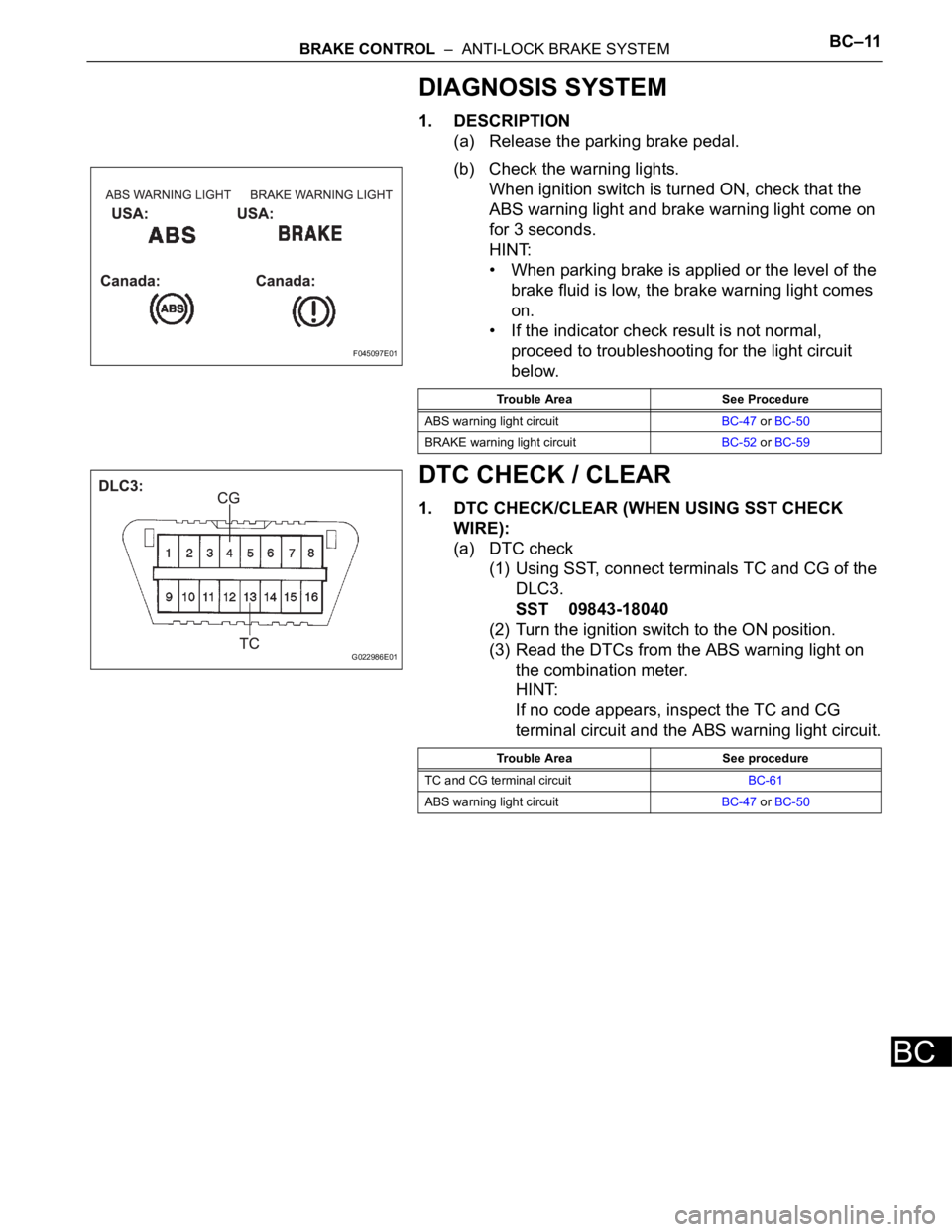
(a) DTC check
(1) Using SST, connect terminals TC and CG of the
DLC3.
SST 09843-18040
(2) Turn the ignition switch to the ON position.
(3) Read the DTCs from the ABS warning light on
the combination meter.
HINT:
If no code appears, inspect the TC and CG
terminal circuit and the ABS warning light circuit.
F045097E01
Trouble Area See Procedure
ABS warning light circuitBC-47 or BC-50
BRAKE warning light circuitBC-52 or BC-59
G022986E01
Trouble Area See procedure
TC and CG terminal circuitBC-61
ABS warning light circuitBC-47 or BC-50
Page 2381 of 3000
BRAKE CONTROL – ANTI-LOCK BRAKE SYSTEMBC–11
BC
DIAGNOSIS SYSTEM
1. DESCRIPTION
(a) Release the parking brake pedal.
(b) Check the warning lights.
When ignition switch is turned ON, check that the
ABS warning light and brake warning light come on
for 3 seconds.
HINT:
• When parking brake is applied or the level of the
brake fluid is low, the brake warning light comes
on.
• If the indicator check result is not normal,
proceed to troubleshooting for the light circuit
below.
DTC CHECK / CLEAR
1. DTC CHECK/CLEAR (WHEN USING SST CHECK
WIRE):
(a) DTC check
(1) Using SST, connect terminals TC and CG of the
DLC3.
SST 09843-18040
(2) Turn the ignition switch to the ON position.
(3) Read the DTCs from the ABS warning light on
the combination meter.
HINT:
If no code appears, inspect the TC and CG
terminal circuit and the ABS warning light circuit.
F045097E01
Trouble Area See Procedure
ABS warning light circuitBC-47 or BC-50
BRAKE warning light circuitBC-52 or BC-59
G022986E01
Trouble Area See procedure
TC and CG terminal circuitBC-61
ABS warning light circuitBC-47 or BC-50
Page 2424 of 3000
BRAKE CONTROL – ANTI-LOCK BRAKE SYSTEMBC–63
BC
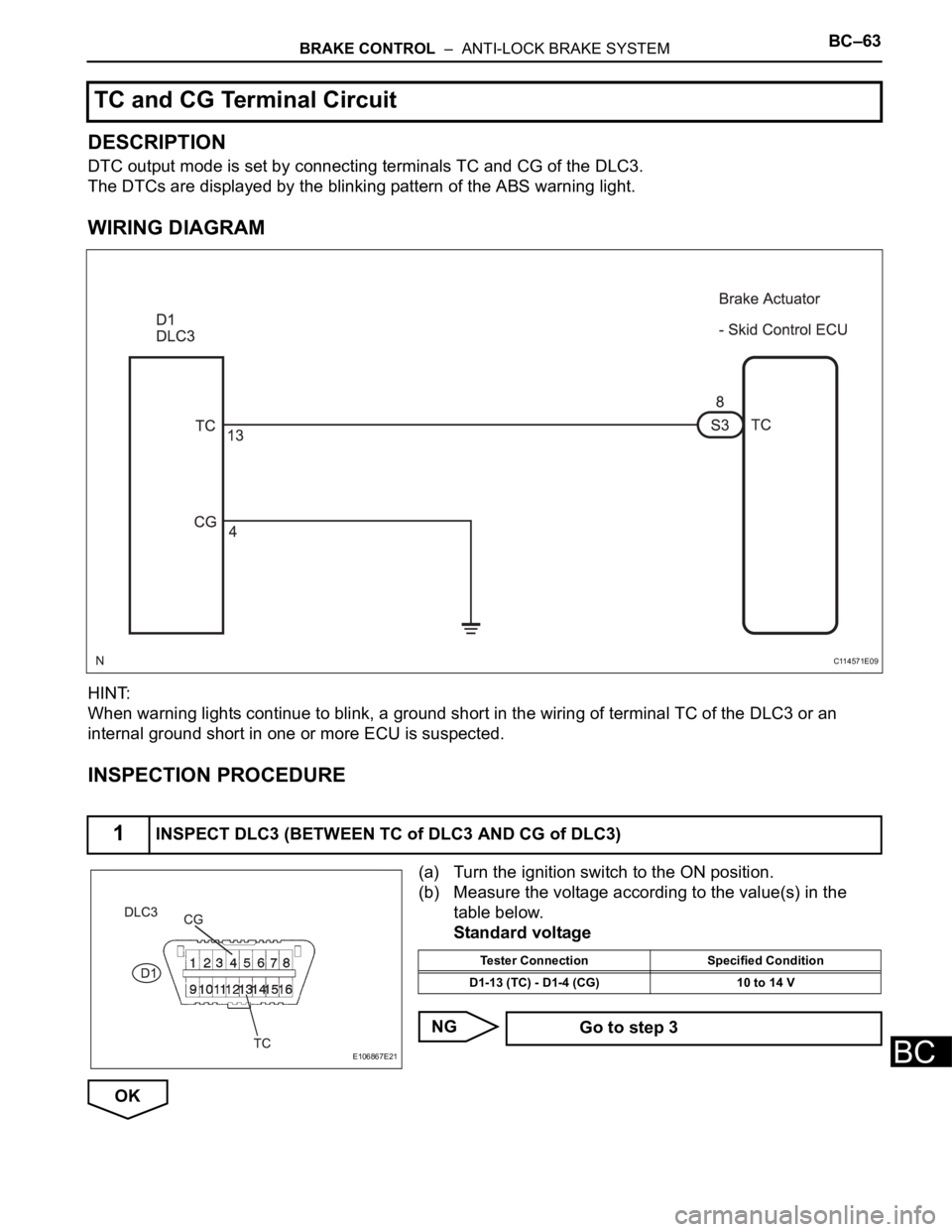
DESCRIPTION
DTC output mode is set by connecting terminals TC and CG of the DLC3.
The DTCs are displayed by the blinking pattern of the ABS warning light.
WIRING DIAGRAM
HINT:
When warning lights continue to blink, a ground short in the wiring of terminal TC of the DLC3 or an
internal ground short in one or more ECU is suspected.
INSPECTION PROCEDURE
(a) Turn the ignition switch to the ON position.
(b) Measure the voltage according to the value(s) in the
table below.
Standard voltage
NG
OK
TC and CG Terminal Circuit
1INSPECT DLC3 (BETWEEN TC of DLC3 AND CG of DLC3)
C114571E09
E106867E21
Tester Connection Specified Condition
D1-13 (TC) - D1-4 (CG) 10 to 14 V
Go to step 3
Page 2437 of 3000
BRAKE CONTROL – VEHICLE STABILITY CONTROL SYSTEMBC–73
BC
TEST MODE PROCEDURE
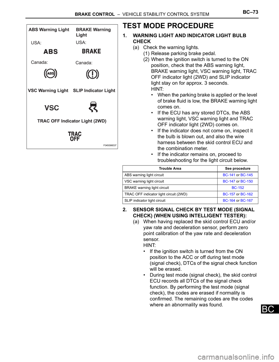
1. WARNING LIGHT AND INDICATOR LIGHT BULB
CHECK
(a) Check the warning lights.
(1) Release parking brake pedal.
(2) When the ignition switch is turned to the ON
position, check that the ABS warning light,
BRAKE warning light, VSC warning light, TRAC
OFF indicator light (2WD) and SLIP indicator
light stay on for approx. 3 seconds.
HINT:
• When the parking brake is applied or the level
of brake fluid is low, the BRAKE warning light
comes on.
• If the ECU has any stored DTCs, the ABS
warning light, VSC warning light and TRAC
OFF indicator light (2WD) comes on.
• If the indicator does not come on, inspect it
the bulb is blown out, and also the wire
harness between the skid control ECU and
the combination meter.
• If the indicator remains on, proceed to
troubleshooting for the light circuit below.
2. SENSOR SIGNAL CHECK BY TEST MODE (SIGNAL
CHECK) (WHEN USING INTELLIGENT TESTER):
(a) When having replaced the skid control ECU and/or
yaw rate and deceleration sensor, perform zero
point calibration of the yaw rate and deceleration
sensor.
HINT:
• If the ignition switch is turned from the ON
position to the ACC or off during test mode
(signal check), DTCs of the signal check function
will be erased.
• During test mode (signal check), the skid control
ECU records all DTCs of the signal check
function. By performing the test mode (signal
check), the codes are erased if normality is
confirmed. The remaining codes are the codes
where an abnormality was found.
F045096E07
Trouble Area See procedure
ABS warning light circuitBC-141 or BC-145
VSC warning light circuitBC-147 or BC-150
BRAKE warning light circuitBC-152
TRAC OFF indicator light circuit (2WD)BC-157 or BC-162
SLIP indicator light circuitBC-164 or BC-167
Page 2446 of 3000
BC–84BRAKE CONTROL – VEHICLE STABILITY CONTROL SYSTEM
BC
DTC CHECK / CLEAR
1. DTC CHECK/CLEAR (WHEN USING INTELLIGENT
TESTER):
(a) DTC check
(1) Connect the intelligent tester to the DLC3.
(2) Turn the ignition switch to the ON position.
(3) Read the DTCs following the prompts on the
tester screen.
(b) DTC clear
(1) Connect the intelligent tester to the DLC3.
(2) Turn the ignition switch to the ON position.
(3) Operate the intelligent tester to clear the codes.
HINT:
Refer to the intelligent tester operator's manual
for further details.
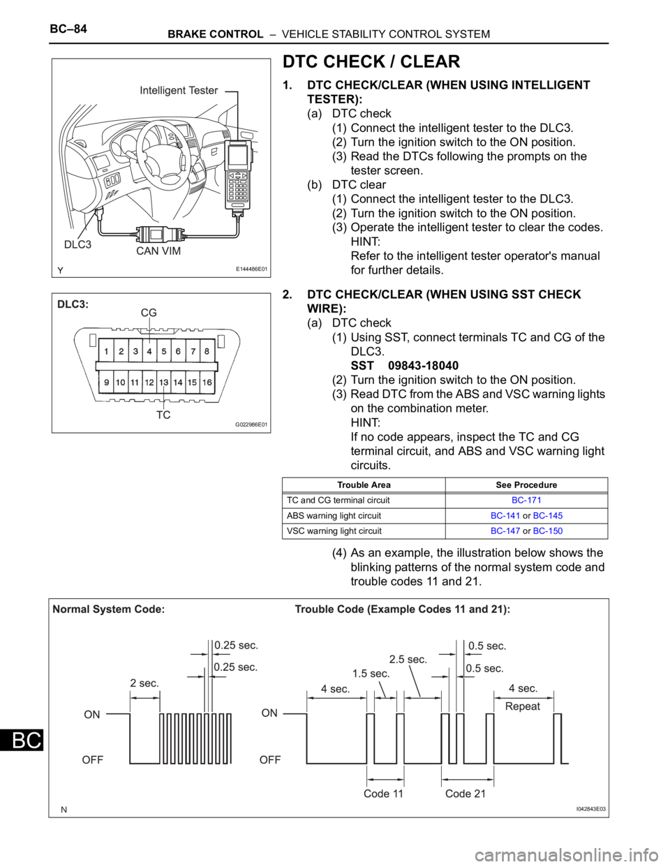
2. DTC CHECK/CLEAR (WHEN USING SST CHECK
WIRE):
(a) DTC check
(1) Using SST, connect terminals TC and CG of the
DLC3.
SST 09843-18040
(2) Turn the ignition switch to the ON position.
(3) Read DTC from the ABS and VSC warning lights
on the combination meter.
HINT:
If no code appears, inspect the TC and CG
terminal circuit, and ABS and VSC warning light
circuits.
(4) As an example, the illustration below shows the
blinking patterns of the normal system code and
trouble codes 11 and 21.
E144486E01
G022986E01
Trouble Area See Procedure
TC and CG terminal circuitBC-171
ABS warning light circuitBC-141 or BC-145
VSC warning light circuitBC-147 or BC-150
I042843E03