2007 TOYOTA SIENNA fuel pump
[x] Cancel search: fuel pumpPage 26 of 3000
2GR-FE ENGINE MECHANICAL – ENGINE ASSEMBLYEM–27
EM
14. REMOVE WINDSHIELD WIPER ARM AND BLADE
ASSEMBLY LH (See page WW-4)
15. REMOVE COWL TOP VENTILATOR LOUVER SUB-
ASSEMBLY (See page WW-4)
16. REMOVE FRONT WIPER MOTOR AND LINK
ASSEMBLY (See page WW-4)
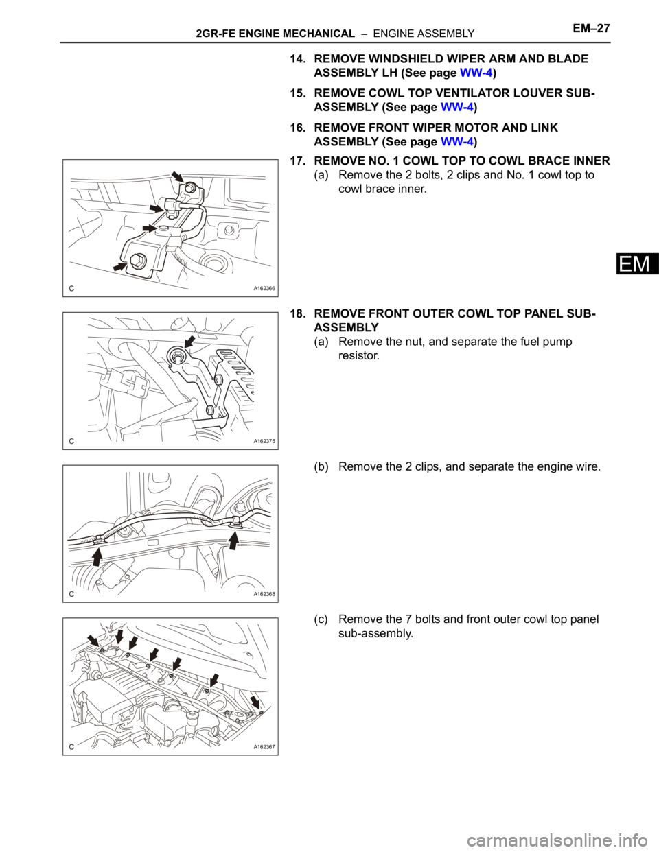
17. REMOVE NO. 1 COWL TOP TO COWL BRACE INNER
(a) Remove the 2 bolts, 2 clips and No. 1 cowl top to
cowl brace inner.
18. REMOVE FRONT OUTER COWL TOP PANEL SUB-
ASSEMBLY
(a) Remove the nut, and separate the fuel pump
resistor.
(b) Remove the 2 clips, and separate the engine wire.
(c) Remove the 7 bolts and front outer cowl top panel
sub-assembly.
A162366
A162375
A162368
A162367
Page 57 of 3000

IN–50INTRODUCTION – TERMS
IN
GLOSSARY OF SAE AND TOYOTA
TERMS
This glossary lists all SAE-J1930 terms and abbreviations
used in this manual in compliance with SAE
recommendations, as well as their TOYOTA equivalents.
SAE
ABBREVIATIONSSAE TERMSTOYOTA TERMS
( )-ABBREVIATIONS
A/C Air Conditioning Air Conditioner
ACL Air Cleaner Air Cleaner, A/CL
AIR Secondary Air Injection Air Injection (AI)
AP Accelerator Pedal -
B+ Battery Positive Voltage +B, Battery Voltage
BARO Barometric Pressure HAC
CAC Charge Air Cooler Intercooler
CARB Carburetor Carburetor
CFI Continuous Fuel Injection -
CKP Crankshaft Position Crank Angle
CL Closed Loop Closed Loop
CMP Camshaft Position Cam Angle
CPP Clutch Pedal Position -
CTOX Continuous Trap Oxidizer -
CTP Closed Throttle Position LL ON, Idle ON
DFI Direct Fuel Injection Direct Injection (DI./INJ)
DI Distributor Ignition -
DLC3 Data Link Connector 3 OBD II Diagnostic Connector
DTC Diagnostic Trouble Code Diagnostic Trouble Code
DTM Diagnostic Test Mode -
ECL Engine Coolant Level -
ECM Engine Control Module Engine Electronic Control Unit (ECU)
ECT Engine Coolant Temperature Coolant Temperature, Water Temperature (THW)
EEPROM Electrically Erasable Programmable Read Only MemoryElectrically Erasable Programmable Read Only
Memory (EEPROM), Erasable Programmable Read
Only Memory (EPROM)
EFE Early Fuel Evaporation Cold Mixture Heater (CMH), Heat Control Valve (HCV)
EGR Exhaust Gas Recirculation Exhaust Gas Recirculation (EGR)
EI Electronic Ignition Distributorless Ignition (DLI)
EM Engine Modification Engine Modification (EM)
EPROM Erasable Programmable Read Only Memory Programmable Read Only Memory (PROM)
EVAP Evaporative Emission Evaporative Emission Control (EVAP)
FC Fan Control -
FEEPROMFlash Electrically Erasable Programmable Read Only
Memory-
FEPROM Flash Erasable Programmable Read Only Memory -
FF Flexible Fuel -
FP Fuel Pump Fuel Pump
GEN Generator Alternator
GND Ground Ground (GND)
HO2S Heated Oxygen SensorHeated Oxygen Sensor (HO
2S)
IAC Idle Air Control Idle Speed Control (ISC)
IAT Intake Air Temperature Intake or Inlet Air Temperature
ICM Ignition Control Module -
Page 197 of 3000

SS–10SERVICE SPECIFICATIONS – 2GR-FE ENGINE MECHANICAL
SS
TORQUE SPECIFICATIONS
Part Tightened N*m kgf*cm ft.*lbf
Ignition coil assembly x Cylinder head cover sub-assembly 10 102 7
No. 1 engine hanger x Cylinder head sub-assembly RH 33 337 24
No. 2 engine hanger x Cylinder head sub-assembly LH 33 337 24
Engine mounting bracket RH x Cylinder block sub-assembly 54 551 40
No. 1 oil level gauge guide x Cylinder head sub-assembly 21 214 15
No. 2 oil level gauge guide x Cylinder block sub-assembly 21 214 15
No. 2 idler pulley sub-assembly x Timing chain cover sub-assembly 43 438 32
V-ribbed belt tensioner assembly x Cylinder block sub-assembly 43 438 32
Intake manifold x Cylinder head sub-assembly 21 214 15
Exhaust manifold sub-assembly RH x Cylinder head sub-assembly
RH21 214 15
Exhaust manifold sub-assembly LH x Cylinder head sub-assembly LH 21 214 15
Drive plate & ring gear sub-assembly x Crankshaft 83 850 61
Air cleaner case sub-assembly x Body 5.0 51 44 in.*lbf
Air cleaner case sub-assembly x Air cleaner bracket 5.0 51 44 in.*lbf
Engine coolant temperature x water by-pass joint RR 20 200 14
Engine assembly with Transaxle x Body A 85 867 63
B 32 329 24
No. 2 manifold stay x Exhaust manifold sub-assembly LH 34 347 25
No. 2 manifold stay x Cylinder block sub-assembly 34 347 25
No. 1 air cleaner inlet x Body 5.0 51 44 in.*lbf
No. 2 air cleaner inlet x Body 5.0 51 44 in.*lbf
Battery clamp x Body Bolt 5.5 56 49 in.*lbf
Nut 5.5 56 49 in.*lbf
Throttle body bracket x Intake air surge tank assembly 21 214 15
Throttle body bracket x Cylinder head cover sub-assembly RH 21 21415
No. 1 surge tank stay x Intake air surge tank assembly 21 214 15
No. 1 surge tank stay x Cylinder head cover sub-assembly RH 21 21415
No. 1 cowl top to cowl brace inner x Body 7.5 76 66 in.*lbf
No. 1 cowl top to cowl brace inner x Front outer cowl top panel sub-
assembly7.5 76 66 in.*lbf
Front outer cowl top panel sub-assembly x Body 7.5 76 66 in.*lbf
Fuel pump resistor x Front outer cowl top panel sub-assembly 7.576 66 in.*lbf
Radio setting condenser x Cylinder head cover sub-assembly RH 10102 7
Radio setting condense x Cylinder head cover sub-assembly LH 10 102 7
Intake air resonator sub-assembly x Body 5.0 51 44 in.*lbf
Air cleaner bracket x Body 7.8 80 69 in.*lbf
No. 1 vacuum switching valve assembly x Cylinder head cover sub-
assembly10 102 7
Engine mounting bracket RR x Cylinder block sub-assembly 64 650 47
Steering intermediate shaft x Steering gear 35 360 26
Stabilizer link x Shock absorber 74 755 55
Tie rod assembly x Steering gear 49 500 36
Front speed sensor x Front axle 8.0 85 71 in.*lbf
Front axle hub nut x Front drive shaft 294 2998 217
Cooler compressor assembly x V-ribbed belt tensioner 25 250 18
Cooler compressor assembly x Discharge hose sub-assembly 5.4 55 48 in.*lbf
Cooler compressor assembly x Suction hose sub-assembly 5.4 55 48 in.*lbf
Page 357 of 3000
2GR-FE ENGINE CONTROL SYSTEM – SFI SYSTEMES–31
ES
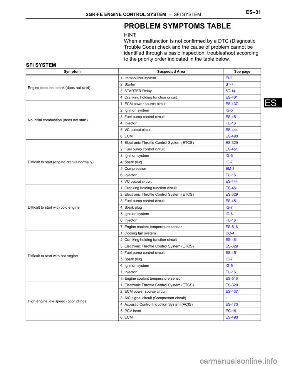
PROBLEM SYMPTOMS TABLE
HINT:
When a malfunction is not confirmed by a DTC (Diagnostic
Trouble Code) check and the cause of problem cannot be
identified through a basic inspection, troubleshoot according
to the priority order indicated in the table below.
SFI SYSTEM
Symptom Suspected Area See page
Engine does not crank (does not start)1. Immobilizer systemEI-2
2. StarterST-7
3. STARTER RelayST-14
4. Cranking holding function circuitES-461
No initial combustion (does not start)1. ECM power source circuitES-437
2. Ignition systemIG-5
3. Fuel pump control circuitES-451
4. InjectorFU-16
5. VC output circuitES-444
6. ECMES-498
Difficult to start (engine cranks normally)1. Electronic Throttle Control System (ETCS)ES-329
2. Fuel pump control circuitES-451
3. Ignition systemIG-5
4. Spark plugIG-7
5. CompressionEM-3
6. InjectorFU-16
7. VC output circuitES-444
Difficult to start with cold engine1. Cranking holding function circuitES-461
2. Electronic Throttle Control System (ETCS)ES-329
3. Fuel pump control circuitES-451
4. Spark plugIG-7
5. Ignition systemIG-6
6. InjectorFU-16
7. Engine coolant temperature sensorES-516
Difficult to start with hot engine1. Cooling fan systemCO-4
2. Cranking holding function circuitES-461
3. Electronic Throttle Control System (ETCS)ES-329
4. Fuel pump control circuitES-451
5. Spark plugIG-7
6. Ignition systemIG-5
7. InjectorFU-16
8. Engine coolant temperature sensorES-516
High engine idle speed (poor idling)1. Electronic Throttle Control System (ETCS)ES-329
2. ECM power source circuitES-437
3. A/C signal circuit (Compressor circuit) -
4. Acoustic Control Induction System (ACIS)ES-470
5. PCV hoseEC-15
6. ECMES-498
Page 358 of 3000
ES–322GR-FE ENGINE CONTROL SYSTEM – SFI SYSTEM
ES
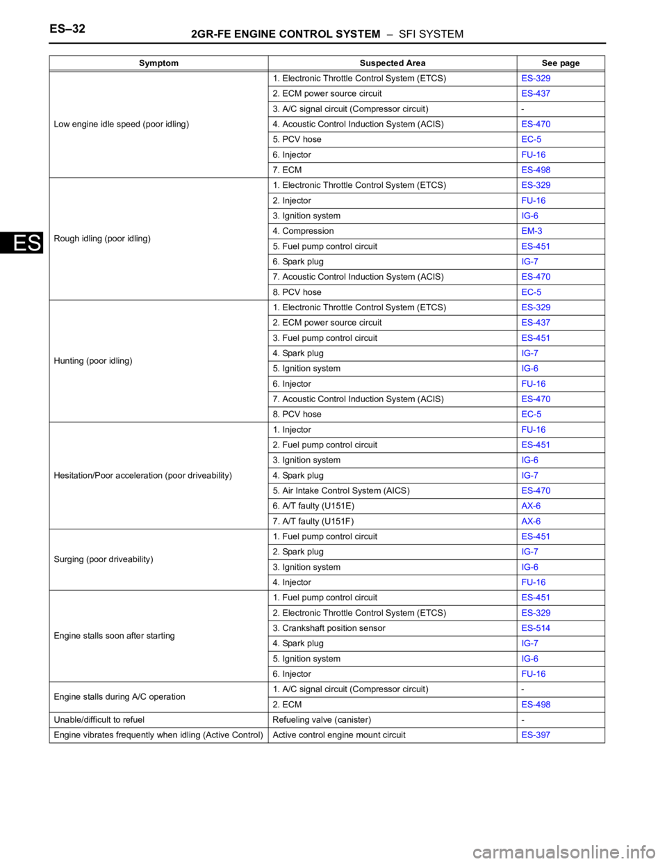
Low engine idle speed (poor idling)1. Electronic Throttle Control System (ETCS)ES-329
2. ECM power source circuitES-437
3. A/C signal circuit (Compressor circuit) -
4. Acoustic Control Induction System (ACIS)ES-470
5. PCV hoseEC-5
6. InjectorFU-16
7. ECMES-498
Rough idling (poor idling)1. Electronic Throttle Control System (ETCS)ES-329
2. InjectorFU-16
3. Ignition systemIG-6
4. CompressionEM-3
5. Fuel pump control circuitES-451
6. Spark plugIG-7
7. Acoustic Control Induction System (ACIS)ES-470
8. PCV hoseEC-5
Hunting (poor idling)1. Electronic Throttle Control System (ETCS)ES-329
2. ECM power source circuitES-437
3. Fuel pump control circuitES-451
4. Spark plugIG-7
5. Ignition systemIG-6
6. InjectorFU-16
7. Acoustic Control Induction System (ACIS)ES-470
8. PCV hoseEC-5
Hesitation/Poor acceleration (poor driveability)1. InjectorFU-16
2. Fuel pump control circuitES-451
3. Ignition systemIG-6
4. Spark plugIG-7
5. Air Intake Control System (AICS)ES-470
6. A/T faulty (U151E)AX-6
7. A/T faulty (U151F)AX-6
Surging (poor driveability)1. Fuel pump control circuitES-451
2. Spark plugIG-7
3. Ignition systemIG-6
4. InjectorFU-16
Engine stalls soon after starting1. Fuel pump control circuitES-451
2. Electronic Throttle Control System (ETCS)ES-329
3. Crankshaft position sensorES-514
4. Spark plugIG-7
5. Ignition systemIG-6
6. InjectorFU-16
Engine stalls during A/C operation1. A/C signal circuit (Compressor circuit) -
2. ECMES-498
Unable/difficult to refuel Refueling valve (canister) -
Engine vibrates frequently when idling (Active Control) Active control engine mount circuitES-397 Symptom Suspected Area See page
Page 366 of 3000

ES–482GR-FE ENGINE CONTROL SYSTEM – SFI SYSTEM
ES
O2FT B2 S2 Fuel trim at heated oxygen sensor Same as SHORT FT #2
AF FT B1 S1 Fuel trim at A/F sensor -
AF FT B2 S1 Fuel trim at A/F sensor -
CAT TEMP B1 S1 Catalyst temperature -
CAT TEMP B2 S1 Catalyst temperature -
CAT TEMP B1 S2 Catalyst temperature -
CAT TEMP B2 S2 Catalyst temperature -
S O2S B1 S2 Heated oxygen sensor impedance (Sensor 2) -
S O2S B2 S2 Heated oxygen sensor impedance (Sensor 2) -
INI COOL TEMP Initial engine coolant temperature -
INI INTAKE TEMP Initial intake air temperature -
INJ VOL Injection volume -
STARTER SIG Starter signal -
PS SW Power steering signal -
PS SIGNAL Power steering signal (history)This signal status usually ON until ignition
switch turned off
CTP SW Closed throttle position switch -
A/C SIGNAL A/C signal -
ELECT LOAD SIG Electrical load signal -
STOP LIGHT SW Stop light switch -
BATTERY VOLTAGE Battery voltage -
ATM PRESSURE Atmospheric pressure -
FUEL PMP SP CTL Fuel pump speed control status -
ACIS VSVVSV for Air Intake Control Induction System
(AICS)-
VVT CTRL B2 VVT control (bank 2 Intake side) status -
EVAP (Purge) VSV EVAP purge VSV -
FUEL PUMP/SPD Fuel pump speed statusVSV for EVAP controlled by ECM (ground
side duty control)
VACUUM PUMP Key-off EVAP system pump status -
EVAP VENT VAL Key-off EVAP system vent valve status -
FAN MOTOR Electric fan motor -
TC/TE1 TC and TE1 terminals of DLC3 -
ACM ACM control status -
VVTL AIM ANGL #1 VVT aim angle -
VVT CHNG ANGL #1 VVT change angle -
VVT OCV DUTY B1 VVT OCV operation duty -
VVT EX HOLD B1VVT exhaust hold duty ratio learning value
(bank 1 Exhaust side)-
VVT EX CHG ANG1 VVT change angle (bank 1 Exhaust side) -
VVT EX OCV D B1VVT OCV (bank 1 Exhaust side) operation
duty-
VVTL AIM ANGL#2 VVT aim angle (bank 2 Intake side) -
VVT CHNG ANGL#2 VVT change angle (bank 2 Intake side) -
VVT OCV DUTY B2 VVT OCV (bank 2 Intake side) operation duty -
VVT EX HOLD B2VVT exhaust hold duty ratio learning value
(bank 2 Exhaust side)-
VVT EX CHG ANG2 VVT change angle (bank 2 Exhaust side) -
VVT EX OCV D B2VVT OCV (bank 2 Exhaust side) operation
duty- LABEL
(Intelligent Tester Display)Measurement Item Diagnostic Note
Page 377 of 3000
2GR-FE ENGINE CONTROL SYSTEM – SFI SYSTEMES–71
ES
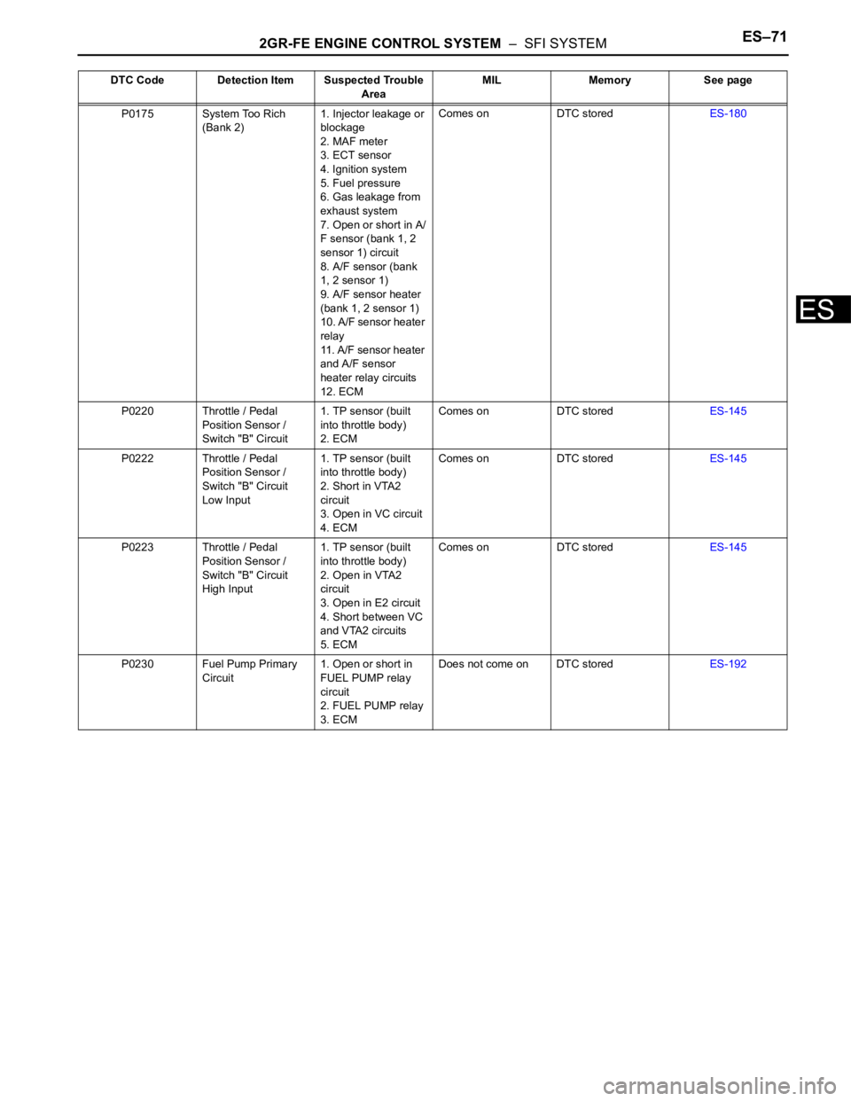
P0175 System Too Rich
(Bank 2)1. Injector leakage or
blockage
2. MAF meter
3. ECT sensor
4. Ignition system
5. Fuel pressure
6. Gas leakage from
exhaust system
7. Open or short in A/
F sensor (bank 1, 2
sensor 1) circuit
8. A/F sensor (bank
1, 2 sensor 1)
9. A/F sensor heater
(bank 1, 2 sensor 1)
10. A/F sensor heater
relay
11. A/F sensor heater
and A/F sensor
heater relay circuits
12. ECMComes on DTC storedES-180
P0220 Throttle / Pedal
Position Sensor /
Switch "B" Circuit1. TP sensor (built
into throttle body)
2. ECMComes on DTC storedES-145
P0222 Throttle / Pedal
Position Sensor /
Switch "B" Circuit
Low Input1. TP sensor (built
into throttle body)
2. Short in VTA2
circuit
3. Open in VC circuit
4. ECMComes on DTC storedES-145
P0223 Throttle / Pedal
Position Sensor /
Switch "B" Circuit
High Input1. TP sensor (built
into throttle body)
2. Open in VTA2
circuit
3. Open in E2 circuit
4. Short between VC
and VTA2 circuits
5. ECMComes on DTC storedES-145
P0230 Fuel Pump Primary
Circuit1. Open or short in
FUEL PUMP relay
circuit
2. FUEL PUMP relay
3. ECMDoes not come on DTC storedES-192 DTC Code Detection Item Suspected Trouble
AreaMIL Memory See page
Page 382 of 3000
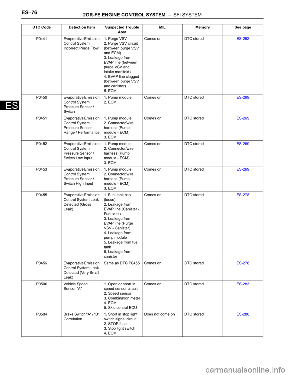
ES–762GR-FE ENGINE CONTROL SYSTEM – SFI SYSTEM
ES
P0441 Evaporative Emission
Control System
Incorrect Purge Flow1. Purge VSV
2. Purge VSV circuit
(between purge VSV
and ECM)
3. Leakage from
EVAP line (between
purge VSV and
intake manifold)
4. EVAP line clogged
(between purge VSV
and canister)
5. ECMComes on DTC storedES-262
P0450 Evaporative Emission
Control System
Pressure Sensor /
Switch1. Pump module
2. ECMComes on DTC storedES-269
P0451 Evaporative Emission
Control System
Pressure Sensor
Range / Performance1. Pump module
2. Connector/wire
harness (Pump
module - ECM)
3. ECMComes on DTC storedES-269
P0452 Evaporative Emission
Control System
Pressure Sensor /
Switch Low Input1. Pump module
2. Connector/wire
harness (Pump
module - ECM)
3. ECMComes on DTC storedES-269
P0453 Evaporative Emission
Control System
Pressure Sensor /
Switch High Input1. Pump module
2. Connector/wire
harness (Pump
module - ECM)
3. ECMComes on DTC storedES-269
P0455 Evaporative Emission
Control System Leak
Detected (Gross
Leak)1. Fuel tank cap
(loose)
2. Leakage from
EVAP line (Canister -
Fuel tank)
3. Leakage from
EVAP line (Purge
VSV - Canister)
4. Leakage from
pump module
5. Leakage from fuel
tank
6. Leakage from
canisterComes on DTC storedES-278
P0456 Evaporative Emission
Control System Leak
Detected (Very Small
Leak)Same as DTC P0455 Comes on DTC storedES-278
P0500 Vehicle Speed
Sensor "A"1. Open or short in
speed sensor circuit
2. Speed sensor
3. Combination meter
4. ECM
5. Skid control ECUComes on DTC storedES-283
P0504 Brake Switch "A" / "B"
Correlation1. Short in stop light
switch signal circuit
2. STOP fuse
3. Stop light switch
4. ECMDoes not come on DTC storedES-288 DTC Code Detection Item Suspected Trouble
AreaMIL Memory See page