Page 386 of 3000
ES–802GR-FE ENGINE CONTROL SYSTEM – SFI SYSTEM
ES
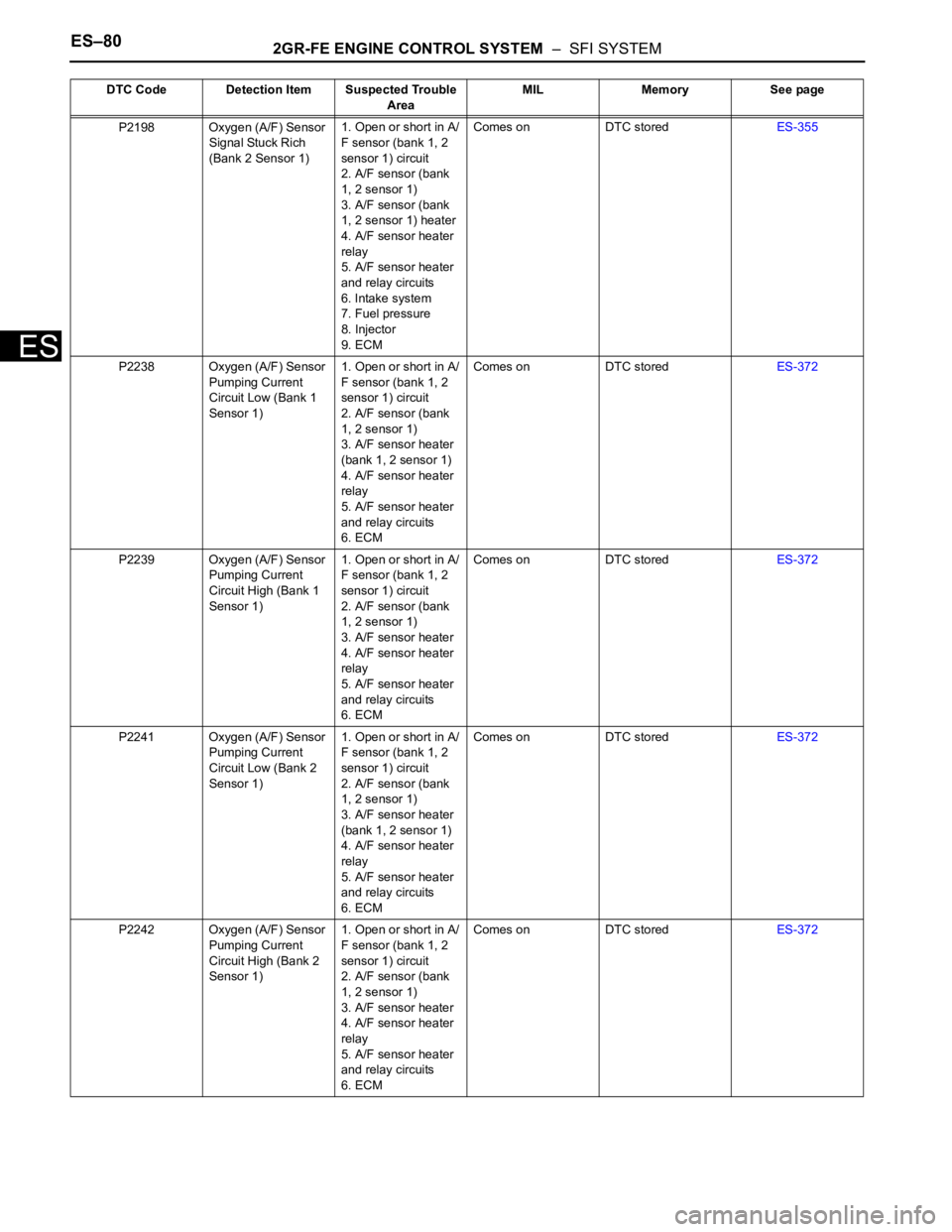
P2198 Oxygen (A/F) Sensor
Signal Stuck Rich
(Bank 2 Sensor 1)1. Open or short in A/
F sensor (bank 1, 2
sensor 1) circuit
2. A/F sensor (bank
1, 2 sensor 1)
3. A/F sensor (bank
1, 2 sensor 1) heater
4. A/F sensor heater
relay
5. A/F sensor heater
and relay circuits
6. Intake system
7. Fuel pressure
8. Injector
9. ECMComes on DTC storedES-355
P2238 Oxygen (A/F) Sensor
Pumping Current
Circuit Low (Bank 1
Sensor 1)1. Open or short in A/
F sensor (bank 1, 2
sensor 1) circuit
2. A/F sensor (bank
1, 2 sensor 1)
3. A/F sensor heater
(bank 1, 2 sensor 1)
4. A/F sensor heater
relay
5. A/F sensor heater
and relay circuits
6. ECMComes on DTC storedES-372
P2239 Oxygen (A/F) Sensor
Pumping Current
Circuit High (Bank 1
Sensor 1)1. Open or short in A/
F sensor (bank 1, 2
sensor 1) circuit
2. A/F sensor (bank
1, 2 sensor 1)
3. A/F sensor heater
4. A/F sensor heater
relay
5. A/F sensor heater
and relay circuits
6. ECMComes on DTC storedES-372
P2241 Oxygen (A/F) Sensor
Pumping Current
Circuit Low (Bank 2
Sensor 1)1. Open or short in A/
F sensor (bank 1, 2
sensor 1) circuit
2. A/F sensor (bank
1, 2 sensor 1)
3. A/F sensor heater
(bank 1, 2 sensor 1)
4. A/F sensor heater
relay
5. A/F sensor heater
and relay circuits
6. ECMComes on DTC storedES-372
P2242 Oxygen (A/F) Sensor
Pumping Current
Circuit High (Bank 2
Sensor 1)1. Open or short in A/
F sensor (bank 1, 2
sensor 1) circuit
2. A/F sensor (bank
1, 2 sensor 1)
3. A/F sensor heater
4. A/F sensor heater
relay
5. A/F sensor heater
and relay circuits
6. ECMComes on DTC storedES-372 DTC Code Detection Item Suspected Trouble
AreaMIL Memory See page
Page 437 of 3000
2GR-FE ENGINE CONTROL SYSTEM – SFI SYSTEMES–131
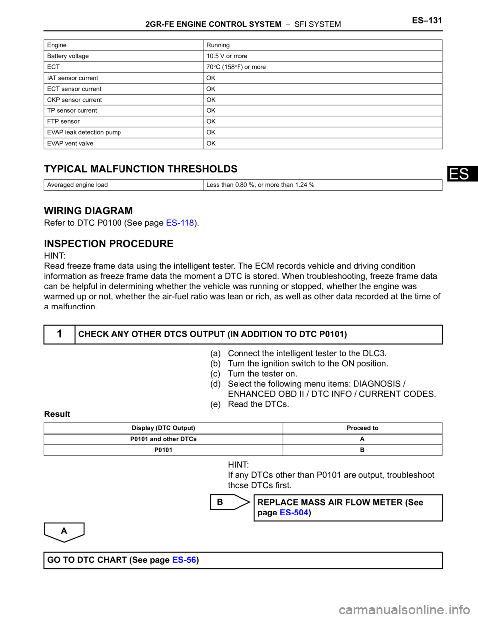
ESTYPICAL MALFUNCTION THRESHOLDS
WIRING DIAGRAM
Refer to DTC P0100 (See page ES-118).
INSPECTION PROCEDURE
HINT:
Read freeze frame data using the intelligent tester. The ECM records vehicle and driving condition
information as freeze frame data the moment a DTC is stored. When troubleshooting, freeze frame data
can be helpful in determining whether the vehicle was running or stopped, whether the engine was
warmed up or not, whether the air-fuel ratio was lean or rich, as well as other data recorded at the time of
a malfunction.
(a) Connect the intelligent tester to the DLC3.
(b) Turn the ignition switch to the ON position.
(c) Turn the tester on.
(d) Select the following menu items: DIAGNOSIS /
ENHANCED OBD II / DTC INFO / CURRENT CODES.
(e) Read the DTCs.
Result
HINT:
If any DTCs other than P0101 are output, troubleshoot
those DTCs first.
B
A
Engine Running
Battery voltage 10.5 V or more
ECT 70
C (158F) or more
IAT sensor current OK
ECT sensor current OK
CKP sensor current OK
TP sensor current OK
FTP sensor OK
EVAP leak detection pump OK
EVAP vent valve OK
Averaged engine load Less than 0.80 %, or more than 1.24 %
1CHECK ANY OTHER DTCS OUTPUT (IN ADDITION TO DTC P0101)
Display (DTC Output) Proceed to
P0101 and other DTCs A
P0101 B
REPLACE MASS AIR FLOW METER (See
page ES-504)
GO TO DTC CHART (See page ES-56)
Page 506 of 3000

ES–2002GR-FE ENGINE CONTROL SYSTEM – SFI SYSTEM
ES
DESCRIPTION
• This DTC is designed to detect a malfunction in the fuel pump (FUEL PUMP) relay circuit. When the
system is normal, the battery voltage is applied to FPR terminal of the ECM while the FUEL PUMP
relay is turned OFF. If the battery voltage is not applied to the FPR terminal while the FUEL PUMP
relay is OFF, the ECM interprets this as a malfunction. The ECM then illuminates the MIL and sets a
DTC.
• The FUEL PUMP relay switches the fuel pump speed according to the engine conditions. The fuel
pump operates when the ECM receives the starter-operating signal (STA) and crankshaft-rotating
signal (NE). The FUEL PUMP relay is turned ON while the engine is idling or operating at low load.
This causes current to flow through the fuel pump resistor to the fuel pump. The fuel pump then
operates at low speed. The FUEL PUMP relay is turned OFF while the engine is cranking or operating
at high load. The fuel pump then operates at normal speed.
DTC P0230 Fuel Pump Primary Circuit
DTC No. DTC Detection Condition Trouble Area
P0230Open or short in FUEL PUMP relay circuit (1 trip
detection logic)• Open or short in FUEL PUMP relay circuit
• FUEL PUMP relay
•ECM
Page 508 of 3000
ES–2022GR-FE ENGINE CONTROL SYSTEM – SFI SYSTEM
ES
(b) Turn the ignition switch to the ON position and turn the
intelligent tester ON.
(c) Enter the following menus: DIAGNOSIS / ENHANCED
OBD II / ACTIVE TEST / FUEL PUMP SP CTL.
(d) Check the operation of the relay while operating it using
the intelligent tester.
OK:
Operating noise can be heard from the relay.
OK
NG
(a) Remove the FUEL PUMP relay from the engine room
junction block.
(b) Measure the resistance according to the value(s) in the
table below.
Standard resistance
(c) Reinstall the FUEL PUMP relay.
NG
OKCHECK FOR INTERMITTENT PROBLEMS
2INSPECT RELAY (FUEL PUMP RELAY)
A137690
Tester Connection Specified Condition
3 - 4 Below 1
3 - 5 10 k or higher
3 - 410 k
or more
(when battery voltage is applied to terminals 1 and 2)
3 - 5Below 1
(when battery voltage is applied to terminals 1 and 2)
REPLACE RELAY (FUEL PUMP RELAY)
Page 509 of 3000
2GR-FE ENGINE CONTROL SYSTEM – SFI SYSTEMES–203
ES
(a) Remove the FUEL PUMP relay from the engine room
junction block.
(b) Disconnect the E11 ECM connector.
(c) Measure the resistance according to the value(s) in the
table below.
Standard resistance
(d) Reconnect the ECM connector.
(e) Reinstall the FUEL PUMP relay.
NG
OK
3CHECK HARNESS AND CONNECTOR (FUEL PUMP RELAY - ECM)
A163154E03
Tester Connection Specified Condition
FUEL PUMP relay terminal 1 - FPR (E11-30) Below 1
FUEL PUMP relay terminal 1 or FPR (E11-30) - Body
Ground10 k or higher
REPAIR OR REPLACE HARNESS OR
CONNECTOR (FUEL PUMP RELAY - ECM)
REPLACE ECM (See page ES-498)
Page 520 of 3000
ES–2142GR-FE ENGINE CONTROL SYSTEM – SFI SYSTEM
ES
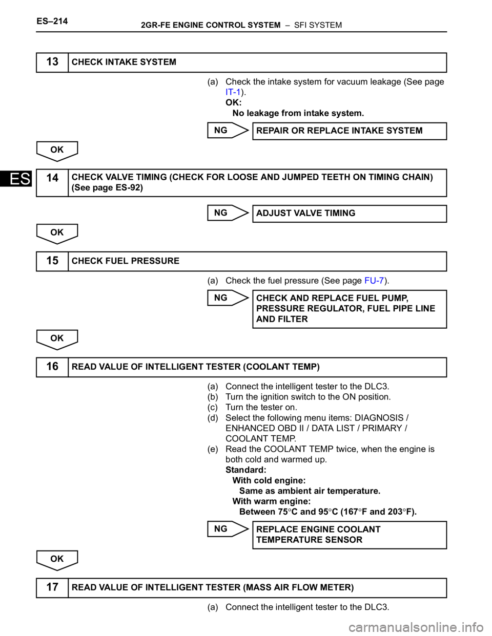
(a) Check the intake system for vacuum leakage (See page
IT-1).
OK:
No leakage from intake system.
NG
OK
NG
OK
(a) Check the fuel pressure (See page FU-7).
NG
OK
(a) Connect the intelligent tester to the DLC3.
(b) Turn the ignition switch to the ON position.
(c) Turn the tester on.
(d) Select the following menu items: DIAGNOSIS /
ENHANCED OBD II / DATA LIST / PRIMARY /
COOLANT TEMP.
(e) Read the COOLANT TEMP twice, when the engine is
both cold and warmed up.
Standard:
With cold engine:
Same as ambient air temperature.
With warm engine:
Between 75
C and 95C (167F and 203F).
NG
OK
(a) Connect the intelligent tester to the DLC3.
13CHECK INTAKE SYSTEM
REPAIR OR REPLACE INTAKE SYSTEM
14CHECK VALVE TIMING (CHECK FOR LOOSE AND JUMPED TEETH ON TIMING CHAIN)
(See page ES-92)
ADJUST VALVE TIMING
15CHECK FUEL PRESSURE
CHECK AND REPLACE FUEL PUMP,
PRESSURE REGULATOR, FUEL PIPE LINE
AND FILTER
16READ VALUE OF INTELLIGENT TESTER (COOLANT TEMP)
REPLACE ENGINE COOLANT
TEMPERATURE SENSOR
17READ VALUE OF INTELLIGENT TESTER (MASS AIR FLOW METER)
Page 521 of 3000
2GR-FE ENGINE CONTROL SYSTEM – SFI SYSTEMES–215
ES
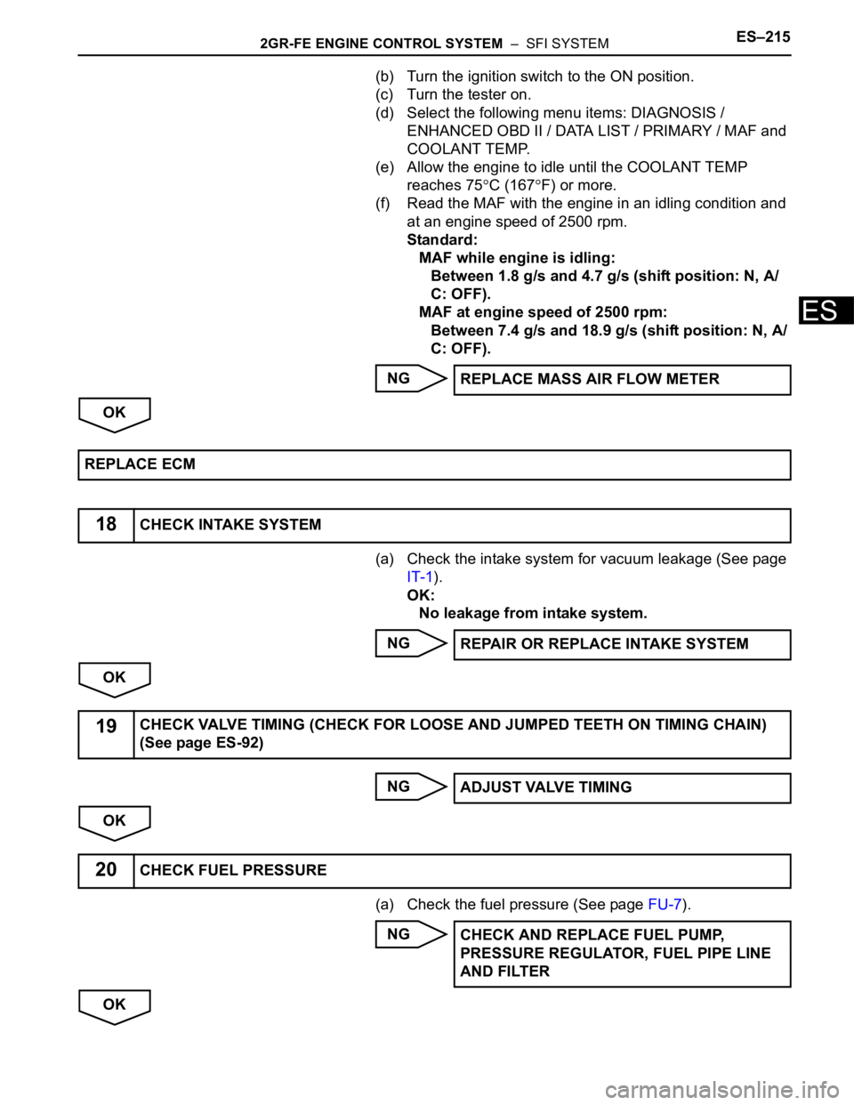
(b) Turn the ignition switch to the ON position.
(c) Turn the tester on.
(d) Select the following menu items: DIAGNOSIS /
ENHANCED OBD II / DATA LIST / PRIMARY / MAF and
COOLANT TEMP.
(e) Allow the engine to idle until the COOLANT TEMP
reaches 75
C (167F) or more.
(f) Read the MAF with the engine in an idling condition and
at an engine speed of 2500 rpm.
Standard:
MAF while engine is idling:
Between 1.8 g/s and 4.7 g/s (shift position: N, A/
C: OFF).
MAF at engine speed of 2500 rpm:
Between 7.4 g/s and 18.9 g/s (shift position: N, A/
C: OFF).
NG
OK
(a) Check the intake system for vacuum leakage (See page
IT-1).
OK:
No leakage from intake system.
NG
OK
NG
OK
(a) Check the fuel pressure (See page FU-7).
NG
OKREPLACE MASS AIR FLOW METER
REPLACE ECM
18CHECK INTAKE SYSTEM
REPAIR OR REPLACE INTAKE SYSTEM
19CHECK VALVE TIMING (CHECK FOR LOOSE AND JUMPED TEETH ON TIMING CHAIN)
(See page ES-92)
ADJUST VALVE TIMING
20CHECK FUEL PRESSURE
CHECK AND REPLACE FUEL PUMP,
PRESSURE REGULATOR, FUEL PIPE LINE
AND FILTER
Page 559 of 3000
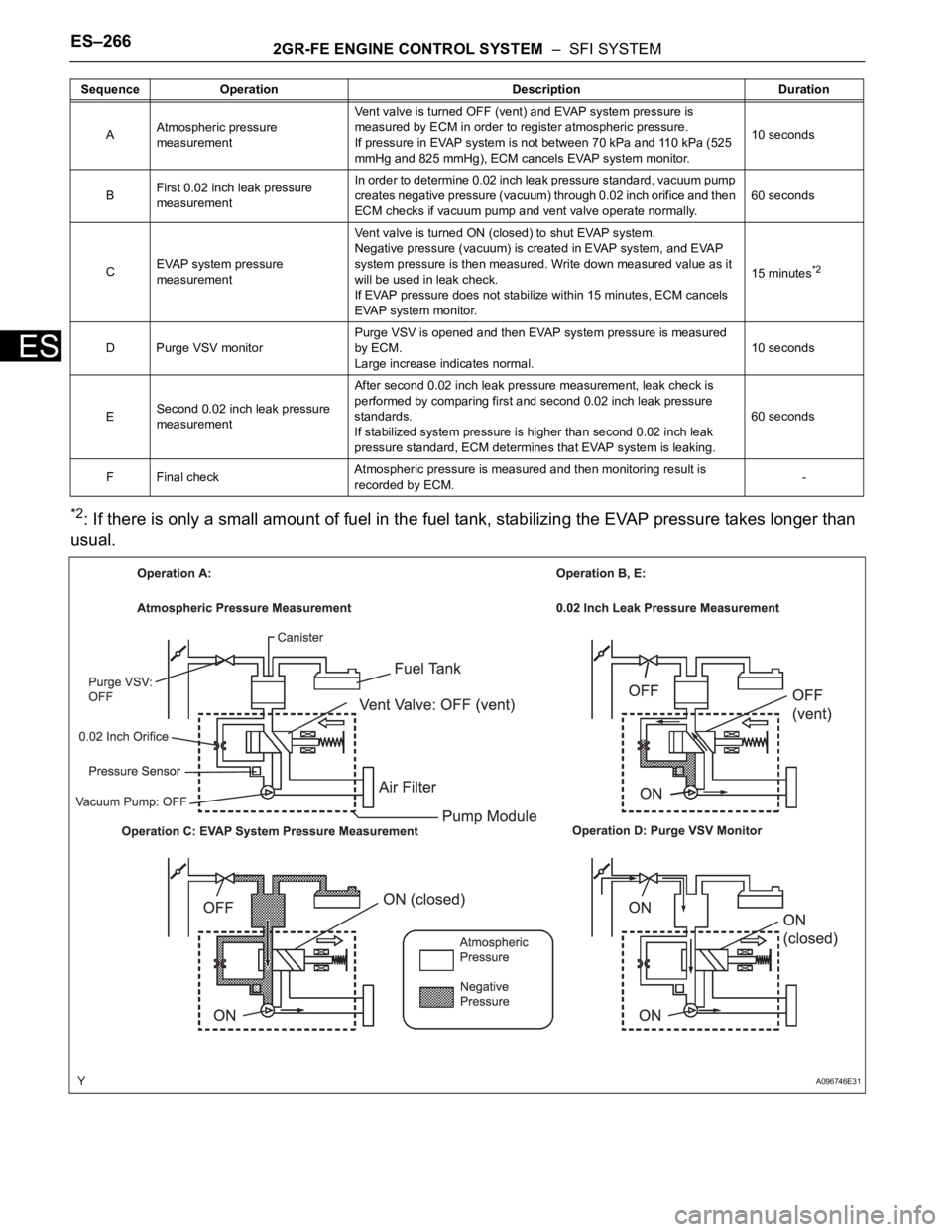
ES–2662GR-FE ENGINE CONTROL SYSTEM – SFI SYSTEM
ES
*2: If there is only a small amount of fuel in the fuel tank, stabilizing the EVAP pressure takes longer than
usual.
AAtmospheric pressure
measurementVent valve is turned OFF (vent) and EVAP system pressure is
measured by ECM in order to register atmospheric pressure.
If pressure in EVAP system is not between 70 kPa and 110 kPa (525
mmHg and 825 mmHg), ECM cancels EVAP system monitor.10 seconds
BFirst 0.02 inch leak pressure
measurementIn order to determine 0.02 inch leak pressure standard, vacuum pump
creates negative pressure (vacuum) through 0.02 inch orifice and then
ECM checks if vacuum pump and vent valve operate normally.60 seconds
CEVAP system pressure
measurementVent valve is turned ON (closed) to shut EVAP system.
Negative pressure (vacuum) is created in EVAP system, and EVAP
system pressure is then measured. Write down measured value as it
will be used in leak check.
If EVAP pressure does not stabilize within 15 minutes, ECM cancels
EVAP system monitor.15 minutes
*2
D Purge VSV monitorPurge VSV is opened and then EVAP system pressure is measured
by ECM.
Large increase indicates normal.10 seconds
ESecond 0.02 inch leak pressure
measurementAfter second 0.02 inch leak pressure measurement, leak check is
performed by comparing first and second 0.02 inch leak pressure
standards.
If stabilized system pressure is higher than second 0.02 inch leak
pressure standard, ECM determines that EVAP system is leaking.60 seconds
F Final checkAtmospheric pressure is measured and then monitoring result is
recorded by ECM.- Sequence Operation Description Duration
A096746E31