2007 TOYOTA SIENNA change wheel
[x] Cancel search: change wheelPage 182 of 3000

BC–6BRAKE CONTROL – ANTI-LOCK BRAKE SYSTEM
BC
HINT:
The codes in this table are output only in Test Mode
(signal check).
4. SPEED SENSOR SIGNAL CHECK (WHEN USING
INTELLIGENT TESTER):
HINT:
• If the ignition switch is turned from the ON to the ACC
or LOCK position during Test Mode, DTCs of the
signal check function will be erased.
• During Test Mode, the ECU records all DTCs of the
signal check function. By performing the signal check,
the codes are erased if normality is confirmed. The
remaining codes are the codes where an abnormality
was found.
(a) Turn the ignition switch off.
(b) Check that the steering wheel is in the straight-
ahead position.
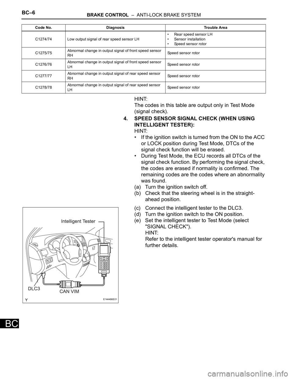
(c) Connect the intelligent tester to the DLC3.
(d) Turn the ignition switch to the ON position.
(e) Set the intelligent tester to Test Mode (select
"SIGNAL CHECK").
HINT:
Refer to the intelligent tester operator's manual for
further details.
C1274/74 Low output signal of rear speed sensor LH• Rear speed sensor LH
• Sensor installation
• Speed sensor rotor
C1275/75Abnormal change in output signal of front speed sensor
RHSpeed sensor rotor
C1276/76Abnormal change in output signal of front speed sensor
LHSpeed sensor rotor
C1277/77Abnormal change in output signal of rear speed sensor
RHSpeed sensor rotor
C1278/78Abnormal change in output signal of rear speed sensor
LHSpeed sensor rotor Code No. Diagnosis Trouble Area
E144486E01
Page 2252 of 3000

TIRE AND WHEEL – TIRE PRESSURE WARNING SYSTEMTW–17
TW
3. WHEN TIRE PRESSURE WARNING LIGHT IS LIT
(a) When the tire pressure warning light does not go off,
or when it comes on during driving, check tire
pressure. If the tire pressure warning light comes on
within several hours after adjusting the tire
pressure, the tire may have a slow air leak.
(b) Under the following conditions, the system may not
function properly.
• Facilities or devices that use similar radio
frequencies are located in the vicinity of the
vehicle.
• A radio device of similar frequency is used in the
vehicle.
• A large amount of snow or ice is stuck to the
vehicle, especially onto the wheels and around
the wheel houses.
• The ID of the tire pressure warning valve and
transmitter has not been registered with the
ECU.
• A film or window tint that may interfere with radio
waves is attached on the glass.
• The battery of the sensor has been depleted.
• The tires without tire pressure warning valve and
transmitter are used.
• Tire chains are used.
• The use of non-genuine wheels may result in the
system failure or air-leak.
• Depending on the tire type, the system may not
function properly even though the specified
wheels are used.
(c) After removing and installing the ECU or a sensor,
check for a diagnostic trouble code and verify that it
is a normal code.
4. FUNCTION OF COMPONENTS
5. TIRE PRESSURE WARNING RESET SWITCH
• By operating the tire pressure warning reset switch,
the tire pressure warning ECU can be set to issue a
warning at an inflation pressure that corresponds to
the standard pressure of tires.
Therefore, the dealer must set the warning threshold
to the proper value in order to comply with the local
regulations.
Components Function
Tire pressure warning valve and transmitterCombined as a single unit with a disc wheel air valve, it measures tire pressure and
temperature and transmits an ID number for measurement value and identification.
Built-in the battery.
Tire pressure warning antenna and receiverReceives and transmits a necessary signal from the transmitter to the tire pressure
warning ECU.
Tire pressure warning ECUReceives a signal from the receiver and identifies it as vehicle's own signal. If the
measured value is equal to or lower than the specified value, it transmits a signal so
that the tire pressure warning light on the combination meter comes on.
Tire pressure warning lightLocated in the combination meter, it informs the driver of lowered tire air pressure
and system failure.
Tire pressure warning reset switch Enters the initialization mode for the change of the standard pressure
Page 2263 of 3000

TIRE AND WHEEL – TIRE PRESSURE WARNING SYSTEMTW–25
TW
INITIALIZATION
1. DESCRIPTION OF INITIALIZATION
(a) Perform initialization in the following cases:
• Before delivery of a new vehicle.
• After replacement of the tire pressure warning
ECU*.
• After replacement of the tire pressure warning
valve and transmitter.
• Specified tire pressure changes depending on
the size or type of the tire.
*: Perform initialization after the transmitter ID
registration is completed (See page TW-20).
(b) Before initialization
(1) Set the air pressure of all tires to the specified
value.
Cold tire inflation pressure
NOTICE:
Perform the tire pressure adjustment after
the vehicle has sufficiently cooled down. If
the vehicle is not sufficiently cooled down,
increase the air pressure by 20 to 30 kPa (0.2
to 0.3 kgf/cm
2, 2.9 to 4.3 psi) above the
specified value.
Tire Size
kPa (kgf/cm2, psi)
P215/65R16
240 (2.4, 35)
P225/60R17
Page 2272 of 3000

TW–22TIRE AND WHEEL – TIRE PRESSURE WARNING SYSTEM
TW
NOTICE:
• The transmitter ID is written on the tire
pressure warning valve and
transmitter. It will be unable to be read
after installing the tire pressure
warning valve and transmitter on the
tire and wheel. Therefore, take a note
of the transmitter ID before installing
the tire pressure warning valve and
transmitter.
• The ID registration must be performed
for all tire pressure warning valve and
transmitters. Check the DATA LIST,
replace the exchanged ID with a new
ID, and make a new data list of all 4
tires for the vehicle.
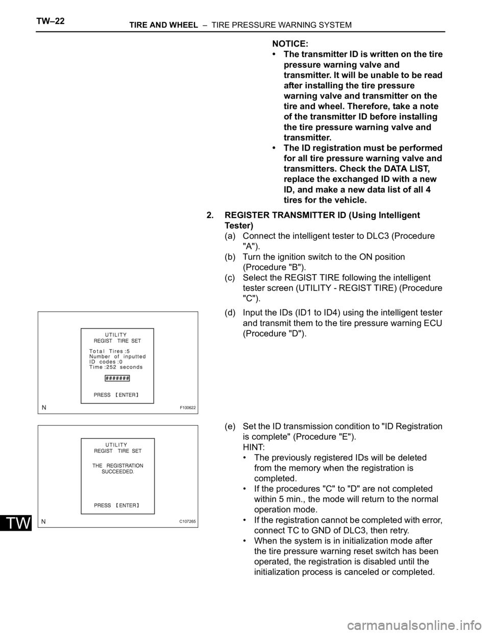
2. REGISTER TRANSMITTER ID (Using Intelligent
Te s t e r )
(a) Connect the intelligent tester to DLC3 (Procedure
"A").
(b) Turn the ignition switch to the ON position
(Procedure "B").
(c) Select the REGIST TIRE following the intelligent
tester screen (UTILITY - REGIST TIRE) (Procedure
"C").
(d) Input the IDs (ID1 to ID4) using the intelligent tester
and transmit them to the tire pressure warning ECU
(Procedure "D").
(e) Set the ID transmission condition to "ID Registration
is complete" (Procedure "E").
HINT:
• The previously registered IDs will be deleted
from the memory when the registration is
completed.
• If the procedures "C" to "D" are not completed
within 5 min., the mode will return to the normal
operation mode.
• If the registration cannot be completed with error,
connect TC to GND of DLC3, then retry.
• When the system is in initialization mode after
the tire pressure warning reset switch has been
operated, the registration is disabled until the
initialization process is canceled or completed.
F100622
C107265
Page 2285 of 3000

TIRE AND WHEEL – TIRE PRESSURE WARNING SYSTEMTW–43
TW
(e) Select "TIREPRESS" by following the prompts displayed
on the intelligent tester.
TIRE PRESSURE:
HINT:
*: It may take about 5 to 6 minutes until the values are
displayed. If the values are not displayed after about 5 to
6 minutes, perform troubleshooting according to the
inspection procedure for DTCs C2121/21 to C2124/24
(See page TW-42).
(f) Rapidly release the pressures from each wheel by
approximately 40 kPa (0.4 kgf/cm
2, 5.8 psi) within 30
seconds.
(1) Check that each tire pressure data displayed on the
intelligent tester screen has changed.
OK:
Each tire pressure data displayed on the
intelligent tester screen will change to the
value of the tire pressure.
NOTICE:
• It takes about 5 to 6 minutes to display the
updated tire pressure data.
• When the "TIREPRESS" data has not
changed, reset the tire pressure to the
appropriate specified value and rotate the tire
90 to 270 degrees (including the spare tire).
Then rapidly release the tire pressure and
recheck it.
(2) After confirming that all of the tire pressure data
displayed on the intelligent tester screen have
changed, set the tire pressure to the appropriate
specified values.
HINT:
If the tire pressure data displayed on the intelligent
tester screen has not changed after rechecking, go
to other problem procedure (for malfunction in
transmission or reception function (See page TW-
42)).
Tester Display Measurement Item/Range Normal Condition Diagnostic Note
TIREPRESS1ID1 tire inflation pressure (Absolute
pressure) /
min.: 100 kPa (1 kgf/cm
2, 14 psi)
max.: 449.35 kPa (4.5 kgf/cm2, 63 psi)Actual tire inflation pressureIf 100 kPa (1 kgf/cm
2, 14 psi) for
absolute pressure is displayed, the
data has not been received.*
TIREPRESS2ID2 tire inflation pressure (Absolute
pressure) /
min.: 100 kPa (1 kgf/cm
2, 14 psi)
max.: 449.35 kPa (4.5 kgf/cm2, 63 psi)Actual tire inflation pressureIf 100 kPa (1 kgf/cm
2, 14 psi) for
absolute pressure is displayed, the
data has not been received.*
TIREPRESS3ID3 tire inflation pressure (Absolute
pressure) /
min.: 100 kPa (1 kgf/cm
2, 14 psi)
max.: 449.35 kPa (4.5 kgf/cm2, 63 psi)Actual tire inflation pressureIf 100 kPa (1 kgf/cm
2, 14 psi) for
absolute pressure is displayed, the
data has not been received.*
TIREPRESS4ID4 tire inflation pressure (Absolute
pressure) /
min.: 100 kPa (1 kgf/cm
2, 14 psi)
max.: 449.35 kPa (4.5 kgf/cm2, 63 psi)Actual tire inflation pressureIf 100 kPa (1 kgf/cm
2, 14 psi) for
absolute pressure is displayed, the
data has not been received.*
Page 2290 of 3000

TW–48TIRE AND WHEEL – TIRE PRESSURE WARNING SYSTEM
TW
(f) Rapidly reduce the tire pressure for each wheel at least
40 kPa (0.41 kg/cm
2, 5.8 psi) within 30 seconds.
(g) Check the DATA LIST.
NOTICE:
• It takes about 5 to 6 minutes to display the
updated tire pressure data.
• When no "TIREPRESS" data has changed, reset
the tire pressure to the appropriate specified
value and rotate the tire 90 to 270 degrees. Then
rapidly release the tire pressure and recheck it.
• Record the transmitter ID of which "TIREPRESS"
data corresponds to each tire.
(h) After confirming that one of "TIREPRESS" data for one
tire (ID1 to ID4) has changed, repeat this procedure one
by one. Identify the transmitter that corresponds to DTC.
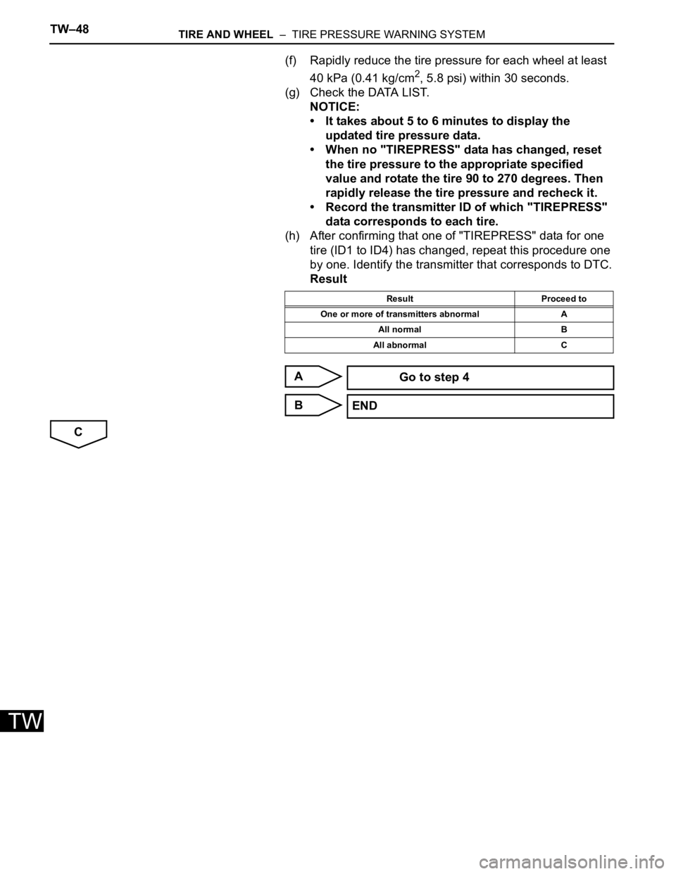
Result
A
B
C
Result Proceed to
One or more of transmitters abnormal A
All normal B
All abnormal C
Go to step 4
END
Page 2296 of 3000

TW–54TIRE AND WHEEL – TIRE PRESSURE WARNING SYSTEM
TW
(f) Rapidly reduce the tire pressure for each wheel at least
40 kPa (0.41 kg/cm
2, 5.8 psi) within 30 seconds. If
"TIREPRESS" displayed on the tester (ID1 to ID4) does
not change, the tire pressure warning valve and
transmitter corresponds to the DTC that was detected.
HINT:
• Identify the malfunctioning tire pressure warning valve
and transmitter by repeatedly decreasing the tire
pressure for each tire.
• Record which "TIREPRESS" data (ID1 to ID4)
corresponds to each tire.
TIRE PRESSURE:
HINT:
*: It may take about 5 to 6 minutes until the values are
displayed. If the values are not displayed after a few
minutes, perform troubleshooting according to the
inspection procedure for DTCs C2121/21 to C2124/24
(See page TW-42).
(g) Check the DATA LIST.
Result
NOTICE:
• When "TIREPRESS" data has not changed, reset
the tire pressure to the appropriate specified
value and rotate the tire 90 to 270 degrees. Then
forcibly transmit the transmitter ID and recheck it.
• Record the transmitter ID and position of
transmitters that are normal.
(h) When the "TIREPRESS" data (ID1 to ID4) has changed,
repeat this procedure to identify the tire pressure
warning valve and transmitter that corresponds to a
DTC.
Tester Display Measurement Item/Range Normal Condition Diagnostic Note
TIREPRESS1ID1 tire inflation pressure (Absolute
pressure) /
min.: 100 kPa (1 kgf/cm
2, 14 psi)
max.: 449.35 kPa (4.5 kgf/cm2, 63 psi)Actual tire inflation pressureIf 100 kPa (1 kgf/cm
2, 14 psi) for
absolute pressure is displayed,
the data has not been received.*
TIREPRESS2ID2 tire inflation pressure (Absolute
pressure) /
min.: 100 kPa (1 kgf/cm
2, 14 psi)
max.: 449.35 kPa (4.5 kgf/cm2, 63 psi)Actual tire inflation pressureIf 100 kPa (1 kgf/cm
2, 14 psi) for
absolute pressure is displayed,
the data has not been received.*
TIREPRESS3ID3 tire inflation pressure (Absolute
pressure) /
min.: 100 kPa (1 kgf/cm
2, 14 psi)
max.: 449.35 kPa (4.5 kgf/cm2, 63 psi)Actual tire inflation pressureIf 100 kPa (1 kgf/cm
2, 14 psi) for
absolute pressure is displayed,
the data has not been received.*
TIREPRESS4ID4 tire inflation pressure (Absolute
pressure) /
min.: 100 kPa (1 kgf/cm
2, 14 psi)
max.: 449.35 kPa (4.5 kgf/cm2, 63 psi)Actual tire inflation pressureIf 100 kPa (1 kgf/cm
2, 14 psi) for
absolute pressure is displayed,
the data has not been received.*
Condition Detection Condition
One of "TIREPRESS" data (ID1 to ID4) changed. Normal
"TIREPRESS" data did not change. Transmitter corresponding to DTC
Page 2297 of 3000

TIRE AND WHEEL – TIRE PRESSURE WARNING SYSTEMTW–55
TW
(i) When all of the "TIREPRESS" data (ID1 to ID4) have
changed, identify the malfunctioning tire pressure
warning valve and transmitter using recorded ID
numbers and output DTC.
(j) Set the tire pressures to the appropriate specified
values.
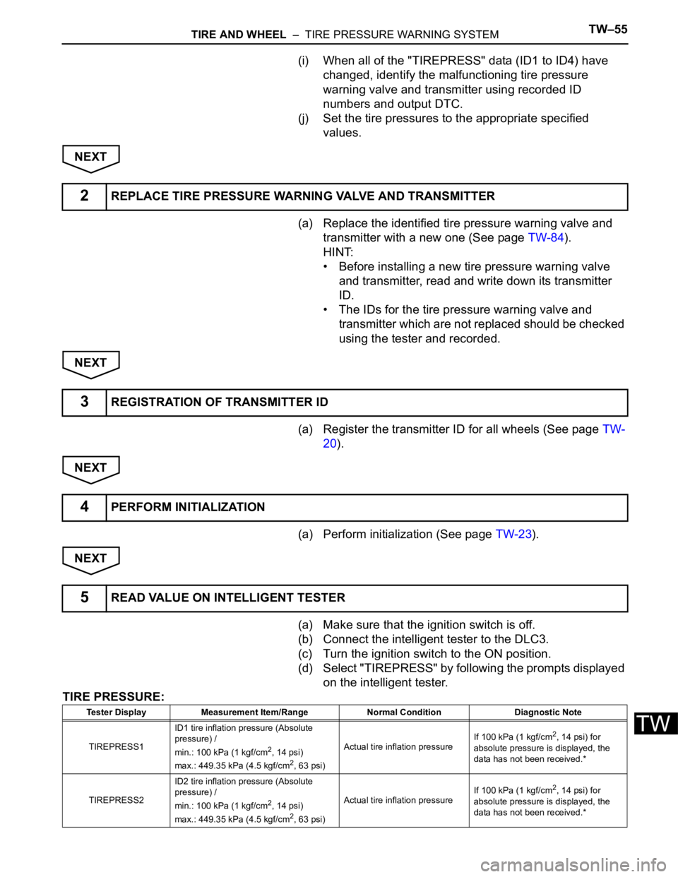
NEXT
(a) Replace the identified tire pressure warning valve and
transmitter with a new one (See page TW-84).
HINT:
• Before installing a new tire pressure warning valve
and transmitter, read and write down its transmitter
ID.
• The IDs for the tire pressure warning valve and
transmitter which are not replaced should be checked
using the tester and recorded.
NEXT
(a) Register the transmitter ID for all wheels (See page TW-
20).
NEXT
(a) Perform initialization (See page TW-23).
NEXT
(a) Make sure that the ignition switch is off.
(b) Connect the intelligent tester to the DLC3.
(c) Turn the ignition switch to the ON position.
(d) Select "TIREPRESS" by following the prompts displayed
on the intelligent tester.
TIRE PRESSURE:
2REPLACE TIRE PRESSURE WARNING VALVE AND TRANSMITTER
3REGISTRATION OF TRANSMITTER ID
4PERFORM INITIALIZATION
5READ VALUE ON INTELLIGENT TESTER
Tester Display Measurement Item/Range Normal Condition Diagnostic Note
TIREPRESS1ID1 tire inflation pressure (Absolute
pressure) /
min.: 100 kPa (1 kgf/cm
2, 14 psi)
max.: 449.35 kPa (4.5 kgf/cm2, 63 psi)Actual tire inflation pressureIf 100 kPa (1 kgf/cm
2, 14 psi) for
absolute pressure is displayed, the
data has not been received.*
TIREPRESS2ID2 tire inflation pressure (Absolute
pressure) /
min.: 100 kPa (1 kgf/cm
2, 14 psi)
max.: 449.35 kPa (4.5 kgf/cm2, 63 psi)Actual tire inflation pressureIf 100 kPa (1 kgf/cm
2, 14 psi) for
absolute pressure is displayed, the
data has not been received.*