2007 TOYOTA SIENNA change wheel
[x] Cancel search: change wheelPage 2300 of 3000

TW–58TIRE AND WHEEL – TIRE PRESSURE WARNING SYSTEM
TW
Cold tire inflation pressure
(b) Make sure that the ignition switch is off.
(c) Connect the intelligent tester to the DLC3.
(d) Turn the ignition switch to the ON position.
(e) Display the "TIREPRESS" data for each wheel using the
intelligent tester.
(f) Rapidly reduce the tire pressure for each wheel at least
40 kPa (0.41 kg/cm
2, 5.8 psi) within 30 seconds.
(g) Check the DATA LIST.
TIRE PRESSURE:
HINT:
*: It may take about 5 to 6 minutes until the values are
displayed. If the values are not displayed after a few
minutes, perform troubleshooting according to the
inspection procedure for DTCs C2121/21 to C2124/24
(See page TW-42).
(h) When the "TIREPRESS" data (ID1 to ID4) has changed,
repeat this procedure to identify the tire pressure
warning valve and transmitter that corresponds to a
DTC.
(i) When all of the "TIREPRESS" data (ID1 to ID4) have
changed, identify the malfunctioning tire pressure
warning valve and transmitter based on the recorded ID
numbers and output DTC.
Result
NOTICE:
• It may take about 5 to 6 minutes to display the
updated data.
Tire Size
kPa (kgf/cm2, psi)
P215/65R16
240 (2.4, 35)
P225/60R17
Tester Display Measurement Item/Range Normal Condition Diagnostic Note
TIREPRESS1ID1 tire inflation pressure (Absolute
pressure) /
min.: 100 kPa (1 kgf/cm
2, 14 psi)
max.: 449.35 kPa (4.5 kgf/cm2, 63 psi)Actual tire inflation pressureIf 100 kPa (1 kgf/cm
2, 14 psi) for
absolute pressure is displayed, the
data has not been received.*
TIREPRESS2ID2 tire inflation pressure (Absolute
pressure) /
min.: 100 kPa (1 kgf/cm
2, 14 psi)
max.: 449.35 kPa (4.5 kgf/cm2, 63 psi)Actual tire inflation pressureIf 100 kPa (1 kgf/cm
2, 14 psi) for
absolute pressure is displayed, the
data has not been received.*
TIREPRESS3ID3 tire inflation pressure (Absolute
pressure) /
min.: 100 kPa (1 kgf/cm
2, 14 psi)
max.: 449.35 kPa (4.5 kgf/cm2, 63 psi)Actual tire inflation pressureIf 100 kPa (1 kgf/cm
2, 14 psi) for
absolute pressure is displayed, the
data has not been received.*
TIREPRESS4ID4 tire inflation pressure (Absolute
pressure) /
min.: 100 kPa (1 kgf/cm
2, 14 psi)
max.: 449.35 kPa (4.5 kgf/cm2, 63 psi)Actual tire inflation pressureIf 100 kPa (1 kgf/cm
2, 14 psi) for
absolute pressure is displayed, the
data has not been received.*
Condition Detection Condition
One of "TIREPRESS" data (ID1 to ID4) changed. Normal
No "TIREPRESS" data changed. Transmitter corresponding to DTC
Page 2301 of 3000
TIRE AND WHEEL – TIRE PRESSURE WARNING SYSTEMTW–59
TW
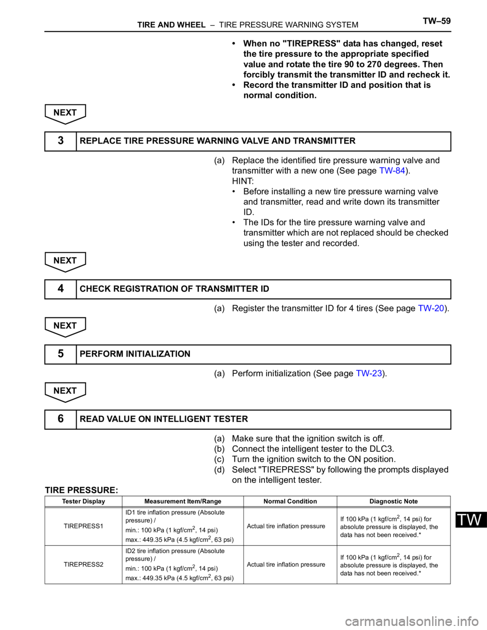
• When no "TIREPRESS" data has changed, reset
the tire pressure to the appropriate specified
value and rotate the tire 90 to 270 degrees. Then
forcibly transmit the transmitter ID and recheck it.
• Record the transmitter ID and position that is
normal condition.
NEXT
(a) Replace the identified tire pressure warning valve and
transmitter with a new one (See page TW-84).
HINT:
• Before installing a new tire pressure warning valve
and transmitter, read and write down its transmitter
ID.
• The IDs for the tire pressure warning valve and
transmitter which are not replaced should be checked
using the tester and recorded.
NEXT
(a) Register the transmitter ID for 4 tires (See page TW-20).
NEXT
(a) Perform initialization (See page TW-23).
NEXT
(a) Make sure that the ignition switch is off.
(b) Connect the intelligent tester to the DLC3.
(c) Turn the ignition switch to the ON position.
(d) Select "TIREPRESS" by following the prompts displayed
on the intelligent tester.
TIRE PRESSURE:
3REPLACE TIRE PRESSURE WARNING VALVE AND TRANSMITTER
4CHECK REGISTRATION OF TRANSMITTER ID
5PERFORM INITIALIZATION
6READ VALUE ON INTELLIGENT TESTER
Tester Display Measurement Item/Range Normal Condition Diagnostic Note
TIREPRESS1ID1 tire inflation pressure (Absolute
pressure) /
min.: 100 kPa (1 kgf/cm
2, 14 psi)
max.: 449.35 kPa (4.5 kgf/cm2, 63 psi)Actual tire inflation pressureIf 100 kPa (1 kgf/cm
2, 14 psi) for
absolute pressure is displayed, the
data has not been received.*
TIREPRESS2ID2 tire inflation pressure (Absolute
pressure) /
min.: 100 kPa (1 kgf/cm
2, 14 psi)
max.: 449.35 kPa (4.5 kgf/cm2, 63 psi)Actual tire inflation pressureIf 100 kPa (1 kgf/cm
2, 14 psi) for
absolute pressure is displayed, the
data has not been received.*
Page 2310 of 3000
TW–68TIRE AND WHEEL – TIRE PRESSURE WARNING SYSTEM
TW
HINT:
*: It may take about 5 to 6 minutes until the values are
displayed. If the values are not displayed after a few
minutes, perform troubleshooting according to the
inspection procedure for DTCs C2121/21 to C2124/24
(See page TW-42).
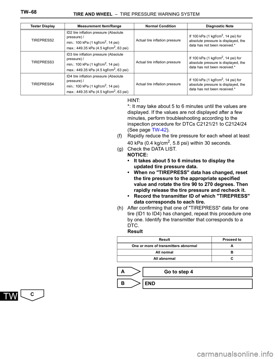
(f) Rapidly reduce the tire pressure for each wheel at least
40 kPa (0.4 kg/cm
2, 5.8 psi) within 30 seconds.
(g) Check the DATA LIST.
NOTICE:
• It takes about 5 to 6 minutes to display the
updated tire pressure data.
• When no "TIREPRESS" data has changed, reset
the tire pressure to the appropriate specified
value and rotate the tire 90 to 270 degrees. Then
rapidly release the tire pressure and recheck it.
• Record the transmitter ID of which "TIREPRESS"
data corresponds to each tire.
(h) After confirming that one of "TIREPRESS" data for one
tire (ID1 to ID4) has changed, repeat this procedure one
by one. Identify the transmitter that corresponds to a
DTC.
Result
A
B
C
TIREPRESS2ID2 tire inflation pressure (Absolute
pressure) /
min.: 100 kPa (1 kgf/cm2, 14 psi)
max.: 449.35 kPa (4.5 kgf/cm2, 63 psi)Actual tire inflation pressureIf 100 kPa (1 kgf/cm
2, 14 psi) for
absolute pressure is displayed, the
data has not been received.*
TIREPRESS3ID3 tire inflation pressure (Absolute
pressure) /
min.: 100 kPa (1 kgf/cm
2, 14 psi)
max.: 449.35 kPa (4.5 kgf/cm2, 63 psi)Actual tire inflation pressureIf 100 kPa (1 kgf/cm
2, 14 psi) for
absolute pressure is displayed, the
data has not been received.*
TIREPRESS4ID4 tire inflation pressure (Absolute
pressure) /
min.: 100 kPa (1 kgf/cm
2, 14 psi)
max.: 449.35 kPa (4.5 kgf/cm2, 63 psi)Actual tire inflation pressureIf 100 kPa (1 kgf/cm
2, 14 psi) for
absolute pressure is displayed, the
data has not been received.* Tester Display Measurement Item/Range Normal Condition Diagnostic Note
Result Proceed to
One or more of transmitters abnormal A
All normal B
All abnormal C
Go to step 4
END
Page 2327 of 3000
TW–22TIRE AND WHEEL – TIRE PRESSURE WARNING SYSTEM
TW
NOTICE:
• The transmitter ID is written on the tire
pressure warning valve and
transmitter. It will be unable to be read
after installing the tire pressure
warning valve and transmitter on the
tire and wheel. Therefore, take a note
of the transmitter ID before installing
the tire pressure warning valve and
transmitter.
• The ID registration must be performed
for all tire pressure warning valve and
transmitters. Check the DATA LIST,
replace the exchanged ID with a new
ID, and make a new data list of all 4
tires for the vehicle.
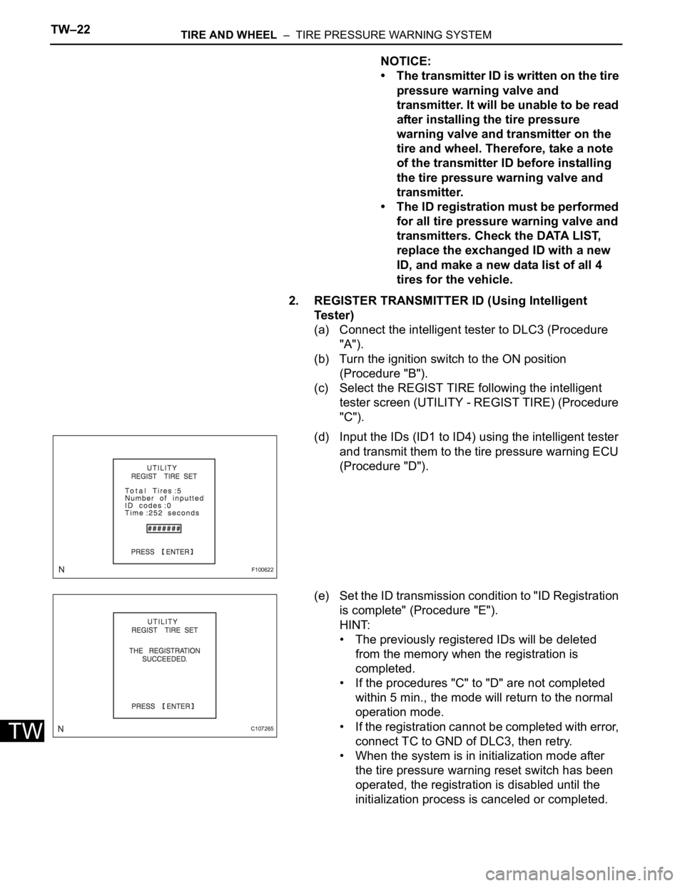
2. REGISTER TRANSMITTER ID (Using Intelligent
Te s t e r )
(a) Connect the intelligent tester to DLC3 (Procedure
"A").
(b) Turn the ignition switch to the ON position
(Procedure "B").
(c) Select the REGIST TIRE following the intelligent
tester screen (UTILITY - REGIST TIRE) (Procedure
"C").
(d) Input the IDs (ID1 to ID4) using the intelligent tester
and transmit them to the tire pressure warning ECU
(Procedure "D").
(e) Set the ID transmission condition to "ID Registration
is complete" (Procedure "E").
HINT:
• The previously registered IDs will be deleted
from the memory when the registration is
completed.
• If the procedures "C" to "D" are not completed
within 5 min., the mode will return to the normal
operation mode.
• If the registration cannot be completed with error,
connect TC to GND of DLC3, then retry.
• When the system is in initialization mode after
the tire pressure warning reset switch has been
operated, the registration is disabled until the
initialization process is canceled or completed.
F100622
C107265
Page 2332 of 3000

TIRE AND WHEEL – TIRE PRESSURE WARNING SYSTEMTW–25
TW
INITIALIZATION
1. DESCRIPTION OF INITIALIZATION
(a) Perform initialization in the following cases:
• Before delivery of a new vehicle.
• After replacement of the tire pressure warning
ECU*.
• After replacement of the tire pressure warning
valve and transmitter.
• Specified tire pressure changes depending on
the size or type of the tire.
*: Perform initialization after the transmitter ID
registration is completed (See page TW-20).
(b) Before initialization
(1) Set the air pressure of all tires to the specified
value.
Cold tire inflation pressure
NOTICE:
Perform the tire pressure adjustment after
the vehicle has sufficiently cooled down. If
the vehicle is not sufficiently cooled down,
increase the air pressure by 20 to 30 kPa (0.2
to 0.3 kgf/cm
2, 2.9 to 4.3 psi) above the
specified value.
Tire Size
kPa (kgf/cm2, psi)
P215/65R16
240 (2.4, 35)
P225/60R17
Page 2370 of 3000
BC–6BRAKE CONTROL – ANTI-LOCK BRAKE SYSTEM
BC
HINT:
The codes in this table are output only in Test Mode
(signal check).
4. SPEED SENSOR SIGNAL CHECK (WHEN USING
INTELLIGENT TESTER):
HINT:
• If the ignition switch is turned from the ON to the ACC
or LOCK position during Test Mode, DTCs of the
signal check function will be erased.
• During Test Mode, the ECU records all DTCs of the
signal check function. By performing the signal check,
the codes are erased if normality is confirmed. The
remaining codes are the codes where an abnormality
was found.
(a) Turn the ignition switch off.
(b) Check that the steering wheel is in the straight-
ahead position.
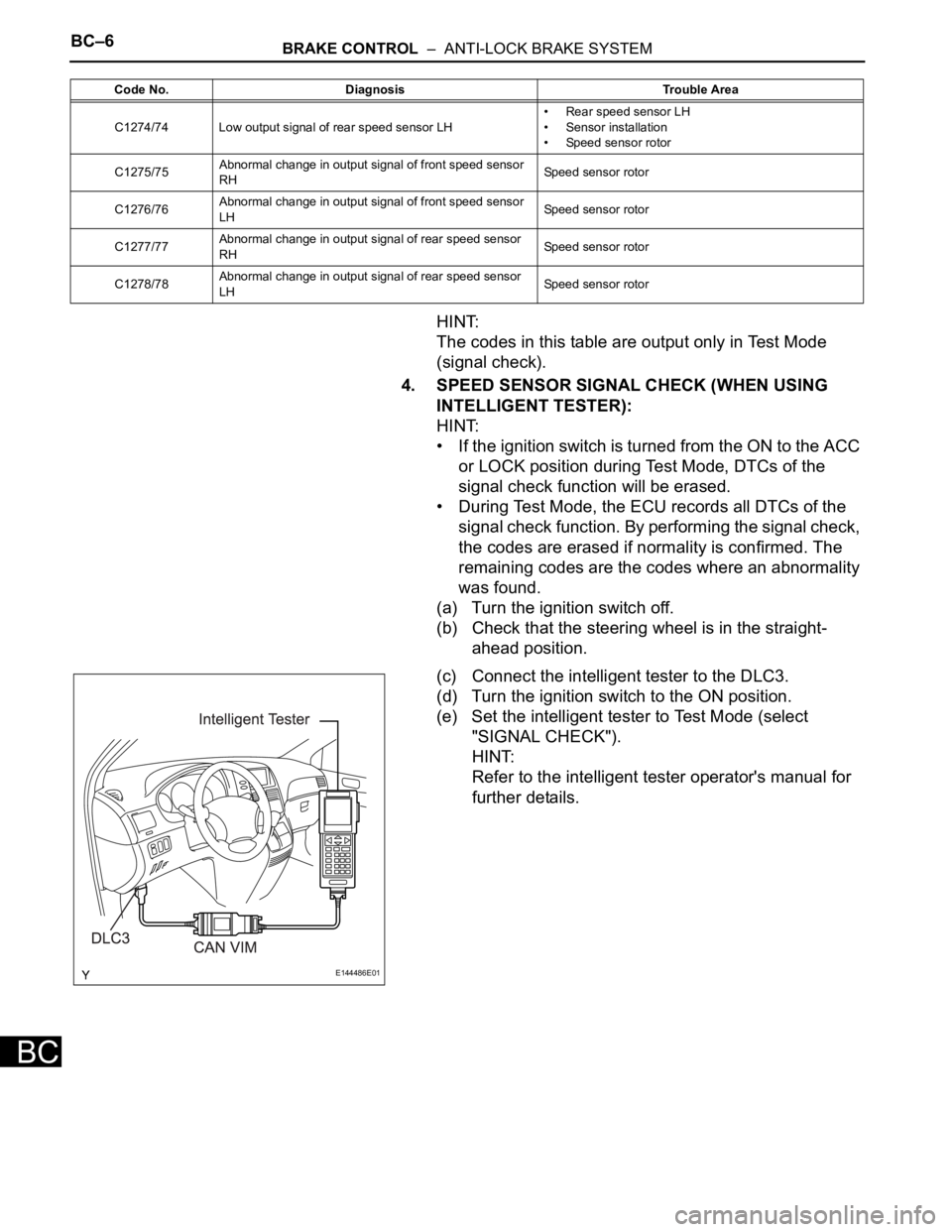
(c) Connect the intelligent tester to the DLC3.
(d) Turn the ignition switch to the ON position.
(e) Set the intelligent tester to Test Mode (select
"SIGNAL CHECK").
HINT:
Refer to the intelligent tester operator's manual for
further details.
C1274/74 Low output signal of rear speed sensor LH• Rear speed sensor LH
• Sensor installation
• Speed sensor rotor
C1275/75Abnormal change in output signal of front speed sensor
RHSpeed sensor rotor
C1276/76Abnormal change in output signal of front speed sensor
LHSpeed sensor rotor
C1277/77Abnormal change in output signal of rear speed sensor
RHSpeed sensor rotor
C1278/78Abnormal change in output signal of rear speed sensor
LHSpeed sensor rotor Code No. Diagnosis Trouble Area
E144486E01
Page 2373 of 3000

BRAKE CONTROL – ANTI-LOCK BRAKE SYSTEMBC–25
BC
DESCRIPTION
Refer to DTCs C0200/31, C0205/32, C1235/35, and C1236/36 (See page BC-17).
DTCs C1273/73 to C1278/78 can be deleted when the speed sensor sends a vehicle speed signal or the
Test Mode ends. DTCs C1273/73 to C1278/78 are output only in the Test Mode.
HINT:
• DTC C0210/33 and C1238/38 are for the rear speed sensor RH.
• DTC C0215/34 and C1239/39 are for the rear speed sensor LH.
DTC C0210/33 Rear Speed Sensor RH Circuit
DTC C0215/34 Rear Speed Sensor LH Circuit
DTC C1238/38Foreign Object is Attached on Tip of Rear
Speed Sensor RH
DTC C1239/39Foreign Object is Attached on Tip of Rear
Speed Sensor LH
DTC C1273/73Low Output Signal of Rear Speed Sensor RH
(Test Mode DTC)
DTC C1274/74Low Output Signal of Rear Speed Sensor LH
(Test Mode DTC)
DTC C1277/77Abnormal Change in Output Signal of Rear
Speed Sensor RH (Test Mode DTC)
DTC C1278/78Abnormal Change in Output Signal of Rear
Speed Sensor LH (Test Mode DTC)
DTC No. DTC Detection Condition Trouble Area
C0210/33
C0215/34With vehicle speed at 10 km/h (6 mph) or more, sensor
signal circuit of faulty wheel is open or short for 1
second or more.
• Momentary interruption of sensor signal of faulty
wheel has occurred 7 times or more.
• Sensor signal circuit is open for 0.5 seconds or
more.• Rear speed sensor RH/LH
• Rear speed sensor RH/LH circuit
• Speed sensor rotor
• Sensor installation
• Brake actuator assembly
C1238/38
C1239/39At vehicle speed of 20 km/h (12 mph) or more, condition
that noise is included in speed sensor signal continues
for 5 seconds or more.• Rear speed sensor RH/LH
• Speed sensor rotor
• Sensor installation
• Brake actuator assembly
Page 2386 of 3000
BRAKE CONTROL – ANTI-LOCK BRAKE SYSTEMBC–19
BC
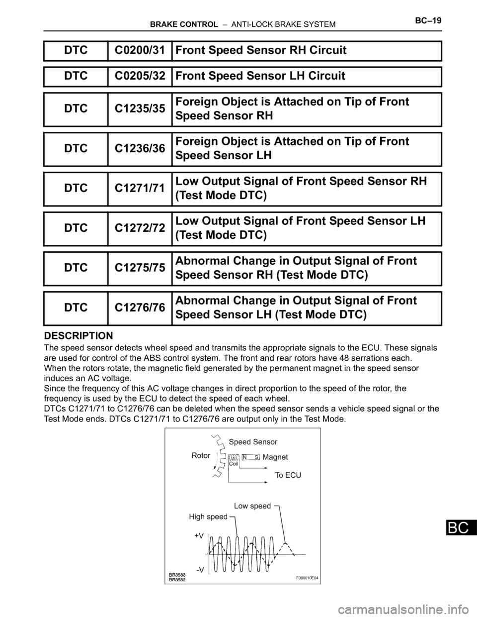
DESCRIPTION
The speed sensor detects wheel speed and transmits the appropriate signals to the ECU. These signals
are used for control of the ABS control system. The front and rear rotors have 48 serrations each.
When the rotors rotate, the magnetic field generated by the permanent magnet in the speed sensor
induces an AC voltage.
Since the frequency of this AC voltage changes in direct proportion to the speed of the rotor, the
frequency is used by the ECU to detect the speed of each wheel.
DTCs C1271/71 to C1276/76 can be deleted when the speed sensor sends a vehicle speed signal or the
Test Mode ends. DTCs C1271/71 to C1276/76 are output only in the Test Mode.
DTC C0200/31 Front Speed Sensor RH Circuit
DTC C0205/32 Front Speed Sensor LH Circuit
DTC C1235/35Foreign Object is Attached on Tip of Front
Speed Sensor RH
DTC C1236/36Foreign Object is Attached on Tip of Front
Speed Sensor LH
DTC C1271/71Low Output Signal of Front Speed Sensor RH
(Test Mode DTC)
DTC C1272/72Low Output Signal of Front Speed Sensor LH
(Test Mode DTC)
DTC C1275/75Abnormal Change in Output Signal of Front
Speed Sensor RH (Test Mode DTC)
DTC C1276/76Abnormal Change in Output Signal of Front
Speed Sensor LH (Test Mode DTC)
F000010E04