Page 21 of 3000
2GR-FE ENGINE CONTROL SYSTEM – KNOCK SENSORES–521
ES
REMOVAL
1. DISCHARGE FUEL SYSTEM PRESSURE
(See page FU-13)
2. REMOVE V-BANK COVER SUB-ASSEMBLY (See
page EM-28)
3. DRAIN ENGINE COOLANT (See page CO-6)
4. REMOVE WINDSHIELD WIPER MOTOR ASSEMBLY
HINT:
(See page WW-4)
5. REMOVE FRONT OUTER COWL TOP PANEL SUB-
ASSEMBLY (See page EM-27)
6. REMOVE AIR CLEANER CAP SUB-ASSEMBLY (See
page ES-493)
7. REMOVE AIR CLEANER CASE SUB-ASSEMBLY (See
page EM-28)
8. REMOVE INTAKE AIR SURGE TANK ASSEMBLY
(a) Disconnect the 2 water by-pass hoses from the
throttle body [A].
(b) Disconnect the vapor feed hose [B].
(c) Disconnect the throttle body connector and clamp
[C].
(d) Disconnect the ventilation hose [D].
(e) Disconnect the union to check valve hose [E].
(f) Disconnect the connector [F].
A129464E07
A138457E04
A129467
Page 23 of 3000
![TOYOTA SIENNA 2007 Service Repair Manual 2GR-FE ENGINE CONTROL SYSTEM – KNOCK SENSORES–523
ES
(a) Install a new gasket to the intake air surge tank [A].
(b) Using a 5 mm hexagon socket wrench, install the 4
bolts [B].
Torque: 18 N*m ( TOYOTA SIENNA 2007 Service Repair Manual 2GR-FE ENGINE CONTROL SYSTEM – KNOCK SENSORES–523
ES
(a) Install a new gasket to the intake air surge tank [A].
(b) Using a 5 mm hexagon socket wrench, install the 4
bolts [B].
Torque: 18 N*m (](/manual-img/14/57466/w960_57466-22.png)
2GR-FE ENGINE CONTROL SYSTEM – KNOCK SENSORES–523
ES
(a) Install a new gasket to the intake air surge tank [A].
(b) Using a 5 mm hexagon socket wrench, install the 4
bolts [B].
Torque: 18 N*m (184 kgf*cm, 13 ft.*lbf)
(c) Install the intake air surge tank with the 2 nuts and 2
bolts [C].
Torque: Nut
16 N*m (163 kgf*cm, 12 ft.*lbf)
Bolt
21 N*m (214 kgf*cm, 15 ft.*lbf)
(d) Connect the connector [D].
(e) Connect the union to check valve hose [E].
(f) Connect the ventilation hose No. 2 [F].
(g) Install the clamp and connect the throttle with motor
body assembly connector [G].
(h) Connect the vapor feed hose [H].
(i) Connect the 2 water by-pass hoses to the throttle
with motor body assembly [I].
5. INSTALL AIR CLEANER CASE SUB-ASSEMBLY (See
page EM-59)
6. INSTALL AIR CLEANER CAP SUB-ASSEMBLY (See
page ES-496)
7. ADD ENGINE COOLANT (See page CO-7)
8. INSPECT FOR ENGINE COOLANT LEAK (See page
CO-1)
9. INSPECT FOR FUEL LEAK (See page FU-7)
10. INSTALL FRONT OUTER COWL TOP PANEL SUB-
ASSEMBLY (See page EM-61)
11. INSTALL WINDSHIELD WIPER MOTOR ASSEMBLY
HINT:
(See page WW-5)
A129468E09
A129467
A138457E05
A129464E08
Page 30 of 3000

2GR-FE ENGINE MECHANICAL – ENGINE ASSEMBLYEM–31
EM
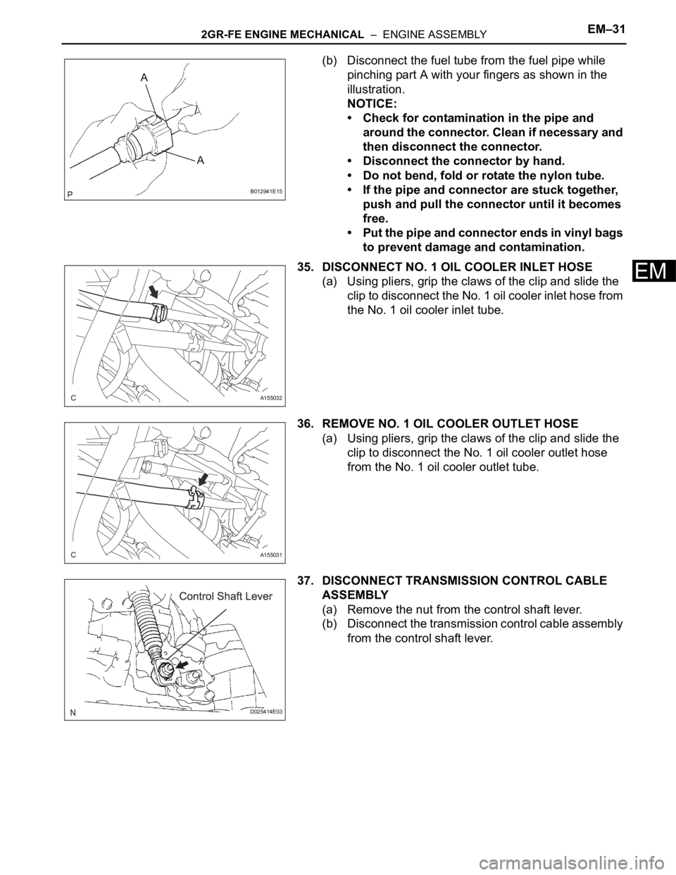
(b) Disconnect the fuel tube from the fuel pipe while
pinching part A with your fingers as shown in the
illustration.
NOTICE:
• Check for contamination in the pipe and
around the connector. Clean if necessary and
then disconnect the connector.
• Disconnect the connector by hand.
• Do not bend, fold or rotate the nylon tube.
• If the pipe and connector are stuck together,
push and pull the connector until it becomes
free.
• Put the pipe and connector ends in vinyl bags
to prevent damage and contamination.
35. DISCONNECT NO. 1 OIL COOLER INLET HOSE
(a) Using pliers, grip the claws of the clip and slide the
clip to disconnect the No. 1 oil cooler inlet hose from
the No. 1 oil cooler inlet tube.
36. REMOVE NO. 1 OIL COOLER OUTLET HOSE
(a) Using pliers, grip the claws of the clip and slide the
clip to disconnect the No. 1 oil cooler outlet hose
from the No. 1 oil cooler outlet tube.
37. DISCONNECT TRANSMISSION CONTROL CABLE
ASSEMBLY
(a) Remove the nut from the control shaft lever.
(b) Disconnect the transmission control cable assembly
from the control shaft lever.
B012941E15
A155032
A155031
D025414E03
Page 32 of 3000
2GR-FE ENGINE MECHANICAL – ENGINE ASSEMBLYEM–33
EM
(b) Remove the bolt and 2 clamps from the body.
(c) Remove the 2 bolts and 2 ground cables.
(d) Disconnect the engine wire from the ECM and
passenger side junction block.
41. DISCONNECT UNION TO CHECK VALVE HOSE
(a) Using pliers, grip the claws of the clip and slide the
clip to disconnect the union to check valve hose.
42. REMOVE CENTER EXHAUST PIPE ASSEMBLY (for
4WD)
(a) Remove the center exhaust pipe assembly (See
page EX-8).
43. REMOVE FRONT EXHAUST PIPE ASSEMBLY (for
4WD)
(a) Remove the front exhaust pipe assembly (See page
EX-9).
44. REMOVE FRONT EXHAUST PIPE ASSEMBLY (for
2WD)
(a) Remove the front exhaust pipe assembly (See page
EX-3).
A155030
A163267
A162374
Page 44 of 3000

2GR-FE EMISSION CONTROL – EMISSION CONTROL SYSTEMEC–5
EC
ON-VEHICLE INSPECTION
1. INSPECT FUEL CUT RPM
(a) Increase the engine speed to at least 3500 rpm.
(b) Use a sound scope to check for injector operating
sounds.
(c) Check that when the throttle lever is released,
injector operating sounds stop momentarily (at 2500
rpm) and then resume (at 1400 rpm).
Standard
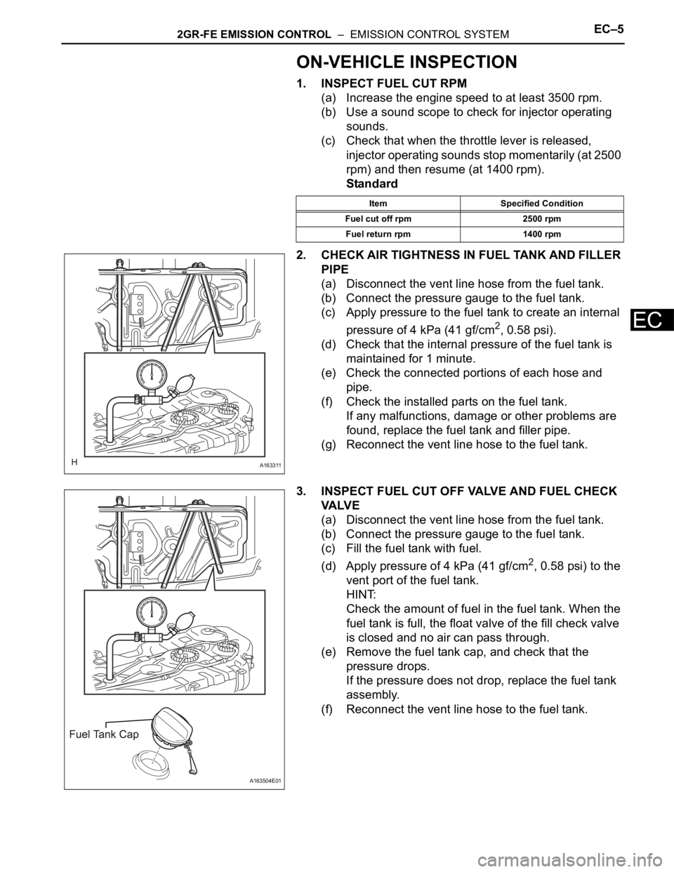
2. CHECK AIR TIGHTNESS IN FUEL TANK AND FILLER
PIPE
(a) Disconnect the vent line hose from the fuel tank.
(b) Connect the pressure gauge to the fuel tank.
(c) Apply pressure to the fuel tank to create an internal
pressure of 4 kPa (41 gf/cm
2, 0.58 psi).
(d) Check that the internal pressure of the fuel tank is
maintained for 1 minute.
(e) Check the connected portions of each hose and
pipe.
(f) Check the installed parts on the fuel tank.
If any malfunctions, damage or other problems are
found, replace the fuel tank and filler pipe.
(g) Reconnect the vent line hose to the fuel tank.
3. INSPECT FUEL CUT OFF VALVE AND FUEL CHECK
VA LV E
(a) Disconnect the vent line hose from the fuel tank.
(b) Connect the pressure gauge to the fuel tank.
(c) Fill the fuel tank with fuel.
(d) Apply pressure of 4 kPa (41 gf/cm
2, 0.58 psi) to the
vent port of the fuel tank.
HINT:
Check the amount of fuel in the fuel tank. When the
fuel tank is full, the float valve of the fill check valve
is closed and no air can pass through.
(e) Remove the fuel tank cap, and check that the
pressure drops.
If the pressure does not drop, replace the fuel tank
assembly.
(f) Reconnect the vent line hose to the fuel tank.
Item Specified Condition
Fuel cut off rpm 2500 rpm
Fuel return rpm 1400 rpm
A163311
A163504E01
Page 45 of 3000
EC–62GR-FE EMISSION CONTROL – EMISSION CONTROL SYSTEM
EC
4. CHECK AIR INLET LINE
(a) Disconnect the air inlet line hose from the charcoal
canister.
(b) Check that air can flow freely into the air inlet line.
If air cannot flow freely into the air inlet line, repair or
replace it.
(c) Reconnect the air inlet line hose to the charcoal
canister.
5. VISUALLY INSPECT HOSES, CONNECTORS AND
GASKETS
(a) Check for cracks, leaks or damage.
HINT:
Removal or problems with the engine oil dipstick, oil
filler cap, PCV hose and other components may
cause the engine to run improperly. Disconnection,
looseness or cracks in the parts of the air induction
system between the throttle body and cylinder head
will allow air suction and cause the engine to run
improperly.
If necessary, replace any damaged parts.
A163329
A094394
Page 48 of 3000

IN–36INTRODUCTION – HOW TO TROUBLESHOOT ECU CONTROLLED SYSTEMS
IN
HOW TO PROCEED WITH
TROUBLESHOOTING
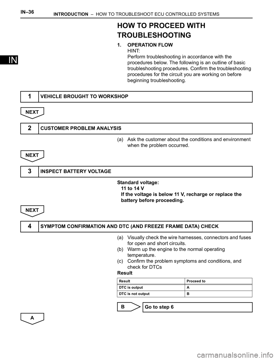
1. OPERATION FLOW
HINT:
Perform troubleshooting in accordance with the
procedures below. The following is an outline of basic
troubleshooting procedures. Confirm the troubleshooting
procedures for the circuit you are working on before
beginning troubleshooting.
NEXT
(a) Ask the customer about the conditions and environment
when the problem occurred.
NEXT
Standard voltage:
11 to 14 V
If the voltage is below 11 V, recharge or replace the
battery before proceeding.
NEXT
(a) Visually check the wire harnesses, connectors and fuses
for open and short circuits.
(b) Warm up the engine to the normal operating
temperature.
(c) Confirm the problem symptoms and conditions, and
check for DTCs
Result
B
A
1VEHICLE BROUGHT TO WORKSHOP
2CUSTOMER PROBLEM ANALYSIS
3INSPECT BATTERY VOLTAGE
4SYMPTOM CONFIRMATION AND DTC (AND FREEZE FRAME DATA) CHECK
Result Proceed to
DTC is output A
DTC is not output B
Go to step 6
Page 51 of 3000

INTRODUCTION – HOW TO TROUBLESHOOT ECU CONTROLLED SYSTEMSIN–39
IN
• In the DTC check, it is very important to determine
whether the problem indicated by the DTC either: 1)
still occurs, or 2) occurred in the past but has returned
to normal. In addition, the DTC should be compared
to the problem symptom to see if they are related. For
this reason, DTCs should be checked before and after
confirmation of symptoms (i.e., whether or not
problem symptoms exist) to determine current system
conditions, as shown in the flowchart below.
• Never skip the DTC check. Failing to check DTCs
may, depending on the case, result in unnecessary
troubleshooting for systems operating normally or
lead to repairs not related to the problem. Follow the
procedures listed in the flowchart in the correct order.
Theft Deterrent System XXXXX
Engine Immobiliser System
XX
Cruise Control SystemXXX
Dynamic Laser Cruise Control System
XXX
Lighting System
XX
Wiper and Washer SystemXXXXX
Power Door Lock Control System X X X
Wireless Door Lock Control SystemXX
Key Reminder Warning System X X XX
Meter / Gauge System X X X
Audio and Visual SystemXXXX
Rear Seat Entertainment System XXXXX
Navigation System
XXXX
Clearance Sonar SystemXXXXX
Rear View Monitor System XXXXX
Power Window Control System (with Jam
Protection Function)XXX
Power Window Control System (without Jam
Protection Function)XXXXX
Power Mirror Control System (with Memory) X X X
Power Mirror Control System (without Memory)XXXXX
Front Power Seat Control System X X X
Rear No. 2 Seat Assembly (with Power Stowing
Function)XXXXX
Window Deogger SystemXXXXX
Power Slide Door System
XX
Slide Door Closer System X X X
Back Door Closer SystemXX
Power Back Door SystemXX
Sliding Roof System XXXXX
Multiplex Communication System XXXXX
CAN Communication System XXXXXSystemSYMPTOM CONFIRMATION AND DIAGNOSTIC TROUBLE CODE
DTC Check
(Normal Mode)DTC Check
(Check Mode)Sensor Check/
Test Mode
(Input Signal
Check)Data List Active Test