2007 TOYOTA SIENNA recommended oil
[x] Cancel search: recommended oilPage 82 of 3000

IG–82GR-FE IGNITION – IGNITION COIL AND SPARK PLUG
IG
(2) Remove the spark plugs.
(3) Visually check the spark plug.
If the electrode is dry, the spark plug is
functioning properly. If the electrode is damp,
proceed to the next step.
(c) Check the spark plug for any damage to its threads
and insulator. If there is damage, replace the spark
plug.
Recommended spark plug
NOTICE:
Use only the listed spark plug or equivalent to
ensure engine performance and smooth
driveability.
(d) Check the spark plug electrode gap.
Maximum electrode gap for used spark plug:
1.4 mm (0.055 in.)
If the gap is greater than the maximum, replace the
spark plug.
Electrode gap for new spark plug:
1.0 to 1.1 mm (0.039 to 0.043 in.)
(e) Clean the spark plugs.
If the electrode has traces of wet carbon, clean the
electrode with a spark plug cleaner and then dry it.
Standard air pressure:
588 kPa (6 kgf*cm
2, 85 psi)
Standard duration:
20 seconds or less
HINT:
Only use the spark plug cleaner when the electrode
is free of oil. If the electrode has traces of oil, use
gasoline to clean off the oil before using the spark
plug cleaner.
(f) Install the ignition coil assembly and spark plug.
(See page IG-10).
Manufacturer Spark Plug Type
DENSO FK20HR11
A163282E01
B062019
Page 196 of 3000
PS–14POWER STEERING – VANE PUMP
PS
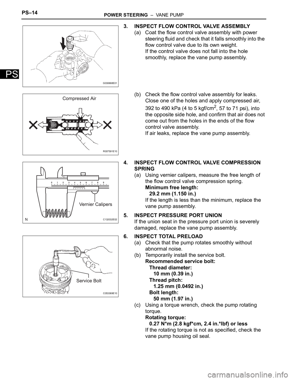
3. INSPECT FLOW CONTROL VALVE ASSEMBLY
(a) Coat the flow control valve assembly with power
steering fluid and check that it falls smoothly into the
flow control valve due to its own weight.
If the control valve does not fall into the hole
smoothly, replace the vane pump assembly.
(b) Check the flow control valve assembly for leaks.
Close one of the holes and apply compressed air,
392 to 490 kPa (4 to 5 kgf/cm
2, 57 to 71 psi), into
the opposite side hole, and confirm that air does not
come out from the holes in the ends of the flow
control valve assembly.
If air leaks, replace the vane pump assembly.
4. INSPECT FLOW CONTROL VALVE COMPRESSION
SPRING
(a) Using vernier calipers, measure the free length of
the flow control valve compression spring.
Minimum free length:
29.2 mm (1.150 in.)
If the length is less than the minimum, replace the
vane pump assembly.
5. INSPECT PRESSURE PORT UNION
If the union seat in the pressure port union is severely
damaged, replace the vane pump assembly.
6. INSPECT TOTAL PRELOAD
(a) Check that the pump rotates smoothly without
abnormal noise.
(b) Temporarily install the service bolt.
Recommended service bolt:
Thread diameter:
10 mm (0.39 in.)
Thread pitch:
1.25 mm (0.0492 in.)
Bolt length:
50 mm (1.97 in.)
(c) Using a torque wrench, check the pump rotating
torque.
Rotating torque:
0.27 N*m (2.8 kgf*cm, 2.4 in.*lbf) or less
If the rotating torque is not as specified, check the
vane pump housing oil seal.
G030668E01
R007591E10
C132032E02
C053369E10
Page 517 of 3000
2GR-FE ENGINE CONTROL SYSTEM – SFI SYSTEMES–211
ES
(d) Read the CYL #1 to #6 or DTCs displayed on the tester.
Result
HINT:
• If it is difficult to reproduce misfires for each cylinder, check
the Data List item called MISFIRE MARGIN. Try to find
vehicle driving conditions that lower the MISFIRE
MARGIN value. Values above 30% are considered normal.
• If the freeze frame data's record of the ECT is below 75
C
(167
F), the misfire may be detected only when the engine
is cold.
• If the freeze frame data's record of the ENG RUN TIME is
below 120 seconds, the misfire may be detected
immediately after the engine is started.
B
A
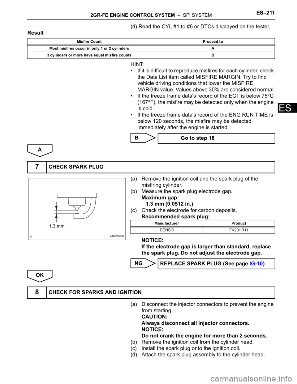
(a) Remove the ignition coil and the spark plug of the
misfiring cylinder.
(b) Measure the spark plug electrode gap.
Maximum gap:
1.3 mm (0.0512 in.)
(c) Check the electrode for carbon deposits.
Recommended spark plug:
NOTICE:
If the electrode gap is larger than standard, replace
the spark plug. Do not adjust the electrode gap.
NG
OK
(a) Disconnect the injector connectors to prevent the engine
from starting.
CAUTION:
Always disconnect all injector connectors.
NOTICE:
Do not crank the engine for more than 2 seconds.
(b) Remove the ignition coil from the cylinder head.
(c) Install the spark plug onto the ignition coil.
(d) Attach the spark plug assembly to the cylinder head.
Misfire Count Proceed to
Most misfires occur in only 1 or 2 cylinders A
3 cylinders or more have equal misfire counts B
Go to step 18
7CHECK SPARK PLUG
A126880E03
Manufacturer Product
DENSO FK20HR11
REPLACE SPARK PLUG (See page IG-10)
8CHECK FOR SPARKS AND IGNITION
Page 523 of 3000
2GR-FE ENGINE CONTROL SYSTEM – SFI SYSTEMES–217
ES
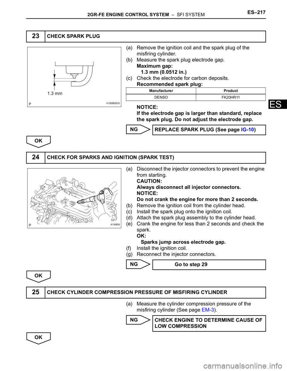
(a) Remove the ignition coil and the spark plug of the
misfiring cylinder.
(b) Measure the spark plug electrode gap.
Maximum gap:
1.3 mm (0.0512 in.)
(c) Check the electrode for carbon deposits.
Recommended spark plug:
NOTICE:
If the electrode gap is larger than standard, replace
the spark plug. Do not adjust the electrode gap.
NG
OK
(a) Disconnect the injector connectors to prevent the engine
from starting.
CAUTION:
Always disconnect all injector connectors.
NOTICE:
Do not crank the engine for more than 2 seconds.
(b) Remove the ignition coil from the cylinder head.
(c) Install the spark plug onto the ignition coil.
(d) Attach the spark plug assembly to the cylinder head.
(e) Crank the engine for less than 2 seconds and check the
spark.
OK:
Sparks jump across electrode gap.
(f) Install the ignition coil.
(g) Reconnect the injector connectors.
NG
OK
(a) Measure the cylinder compression pressure of the
misfiring cylinder (See page EM-3).
NG
OK
23CHECK SPARK PLUG
A126880E03
Manufacturer Product
DENSO FK20HR11
REPLACE SPARK PLUG (See page IG-10)
24CHECK FOR SPARKS AND IGNITION (SPARK TEST)
A136826
Go to step 29
25CHECK CYLINDER COMPRESSION PRESSURE OF MISFIRING CYLINDER
CHECK ENGINE TO DETERMINE CAUSE OF
LOW COMPRESSION
Page 1317 of 3000
IG–82GR-FE IGNITION – IGNITION COIL AND SPARK PLUG
IG
(2) Remove the spark plugs.
(3) Visually check the spark plug.
If the electrode is dry, the spark plug is
functioning properly. If the electrode is damp,
proceed to the next step.
(c) Check the spark plug for any damage to its threads
and insulator. If there is damage, replace the spark
plug.
Recommended spark plug
NOTICE:
Use only the listed spark plug or equivalent to
ensure engine performance and smooth
driveability.
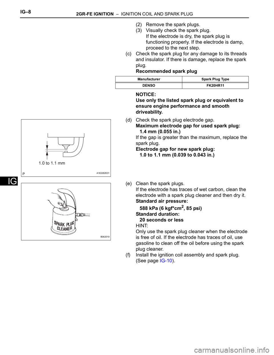
(d) Check the spark plug electrode gap.
Maximum electrode gap for used spark plug:
1.4 mm (0.055 in.)
If the gap is greater than the maximum, replace the
spark plug.
Electrode gap for new spark plug:
1.0 to 1.1 mm (0.039 to 0.043 in.)
(e) Clean the spark plugs.
If the electrode has traces of wet carbon, clean the
electrode with a spark plug cleaner and then dry it.
Standard air pressure:
588 kPa (6 kgf*cm
2, 85 psi)
Standard duration:
20 seconds or less
HINT:
Only use the spark plug cleaner when the electrode
is free of oil. If the electrode has traces of oil, use
gasoline to clean off the oil before using the spark
plug cleaner.
(f) Install the ignition coil assembly and spark plug.
(See page IG-10).
Manufacturer Spark Plug Type
DENSO FK20HR11
A163282E01
B062019
Page 2725 of 3000
PS–14POWER STEERING – VANE PUMP
PS
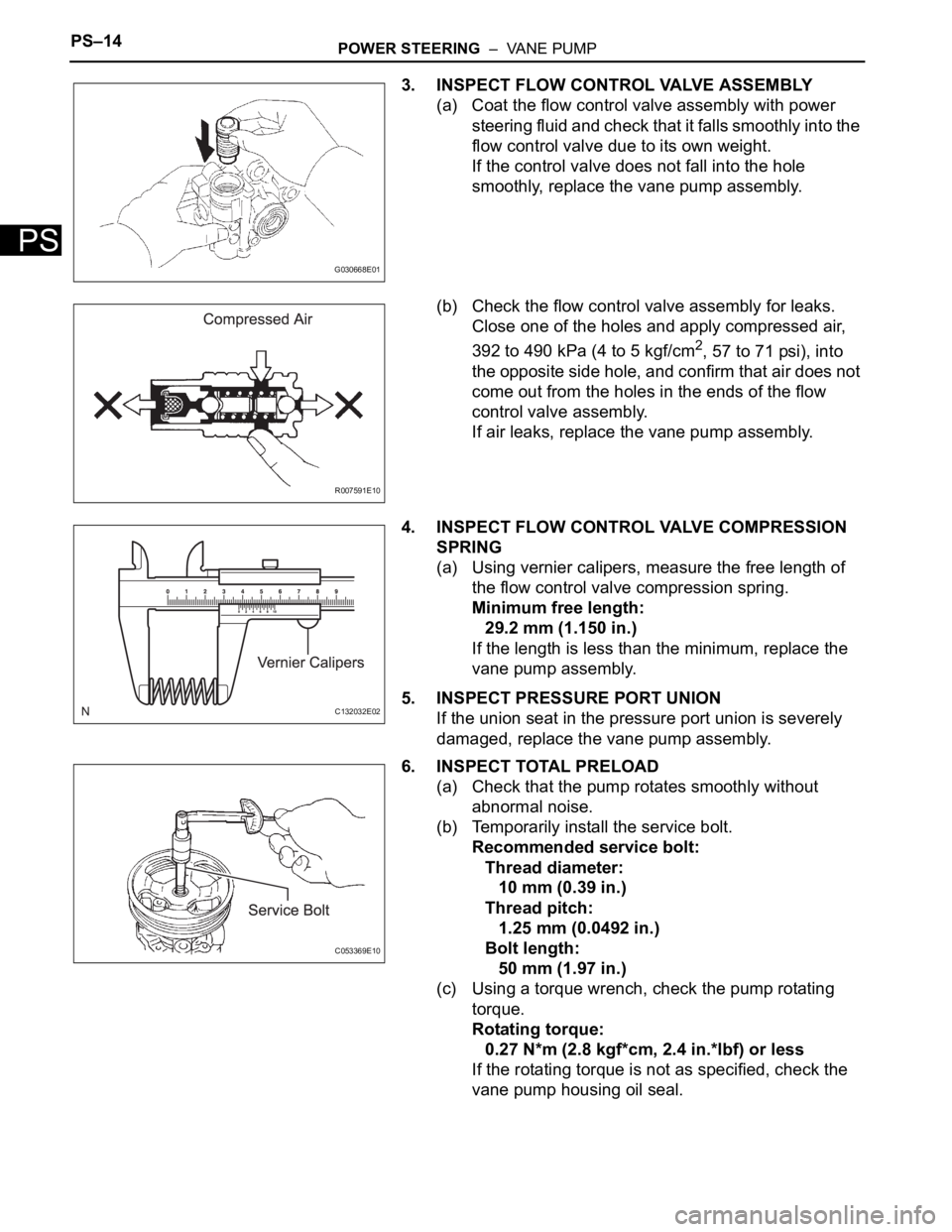
3. INSPECT FLOW CONTROL VALVE ASSEMBLY
(a) Coat the flow control valve assembly with power
steering fluid and check that it falls smoothly into the
flow control valve due to its own weight.
If the control valve does not fall into the hole
smoothly, replace the vane pump assembly.
(b) Check the flow control valve assembly for leaks.
Close one of the holes and apply compressed air,
392 to 490 kPa (4 to 5 kgf/cm
2, 57 to 71 psi), into
the opposite side hole, and confirm that air does not
come out from the holes in the ends of the flow
control valve assembly.
If air leaks, replace the vane pump assembly.
4. INSPECT FLOW CONTROL VALVE COMPRESSION
SPRING
(a) Using vernier calipers, measure the free length of
the flow control valve compression spring.
Minimum free length:
29.2 mm (1.150 in.)
If the length is less than the minimum, replace the
vane pump assembly.
5. INSPECT PRESSURE PORT UNION
If the union seat in the pressure port union is severely
damaged, replace the vane pump assembly.
6. INSPECT TOTAL PRELOAD
(a) Check that the pump rotates smoothly without
abnormal noise.
(b) Temporarily install the service bolt.
Recommended service bolt:
Thread diameter:
10 mm (0.39 in.)
Thread pitch:
1.25 mm (0.0492 in.)
Bolt length:
50 mm (1.97 in.)
(c) Using a torque wrench, check the pump rotating
torque.
Rotating torque:
0.27 N*m (2.8 kgf*cm, 2.4 in.*lbf) or less
If the rotating torque is not as specified, check the
vane pump housing oil seal.
G030668E01
R007591E10
C132032E02
C053369E10