Page 58 of 3000

INTRODUCTION – TERMSIN–51
IN
IFI Indirect Fuel Injection Indirect Injection (IDL)
IFS Inertia Fuel-Shutoff -
ISC Idle Speed Control -
KS Knock Sensor Knock Sensor
MAF Mass Airflow Air Flow Meter
MAP Manifold Absolute Pressure Manifold Pressure Intake Vacuum
MC Mixture ControlElectric Bleed Air Control Valve (EBCV)
Mixture Control Valve (MCV)
Electric Air Control Valve (EACV)
MDP Manifold Differential Pressure -
MFI Multiport Fuel Injection Electronic Fuel Injection (EFI)
MIL Malfunction Indicator Light Check Engine Light
MST Manifold Surface Temperature -
MVZ Manifold Vacuum Zone -
NVRAM Non-Volatile Random Access Memory -
O2S Oxygen SensorOxygen Sensor, O
2 Sensor (O2S)
OBD On-Board Diagnostic On-Board Diagnostic System (OBD)
OC Oxidation Catalytic Converter Oxidation Catalytic Convert (OC), CCo
OL Open Loop Open Loop
PAIR Pulsed Secondary Air Injection Air Suction (AS)
PCM Powertrain Control Module -
PNP Park/Neutral Position -
PROM Programmable Read Only Memory -
PSP Power Steering Pressure -
PTOX Periodic Trap OxidizerDiesel Particulate Filter (DPF)
Diesel Particulate Trap (DPT)
RAM Random Access Memory Random Access Memory (RAM)
RM Relay Module -
ROM Read Only Memory Read Only Memory (ROM)
RPM Engine Speed Engine Speed
SC Supercharger Supercharger
SCB Supercharger Bypass E-ABV
SFI Sequential Multiport Fuel Injection Electronic Fuel Injection (EFI), Sequential Injection
SPL Smoke Puff Limiter -
SRI Service Reminder Indicator -
SRT System Readiness Test -
ST Scan Tool -
TB Throttle Body Throttle Body
TBI Throttle Body Fuel InjectionSingle Point Injection
Central Fuel Injection (Ci)
TC Turbocharger Turbocharger
TCC Torque Converter Clutch Torque Converter
TCM Transmission Control Module Transmission ECU, ECT ECU
TP Throttle Position Throttle Position
TR Transmission Range -
TVV Thermal Vacuum ValveBimetallic Vacuum Switching Valve (BVSV)
Thermostatic Vacuum Switching Valve (TVSV)
TWC Three-Way Catalytic ConverterThree-Way Catalytic (TWC)
Manifold Converter
CC
RO
SAE
ABBREVIATIONSSAE TERMSTOYOTA TERMS
( )-ABBREVIATIONS
Page 361 of 3000

2GR-FE ENGINE CONTROL SYSTEM – SFI SYSTEMES–43
ES
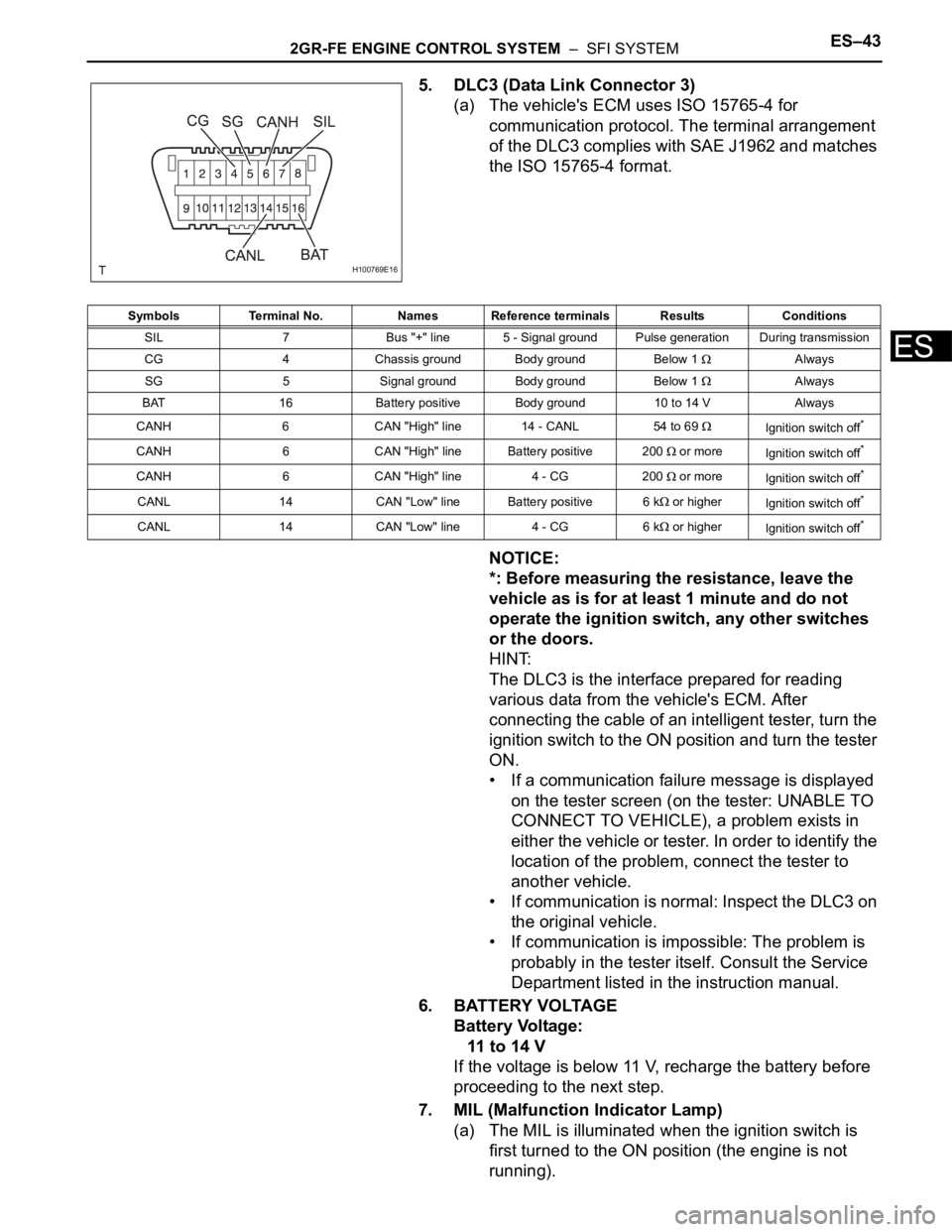
5. DLC3 (Data Link Connector 3)
(a) The vehicle's ECM uses ISO 15765-4 for
communication protocol. The terminal arrangement
of the DLC3 complies with SAE J1962 and matches
the ISO 15765-4 format.
NOTICE:
*: Before measuring the resistance, leave the
vehicle as is for at least 1 minute and do not
operate the ignition switch, any other switches
or the doors.
HINT:
The DLC3 is the interface prepared for reading
various data from the vehicle's ECM. After
connecting the cable of an intelligent tester, turn the
ignition switch to the ON position and turn the tester
ON.
• If a communication failure message is displayed
on the tester screen (on the tester: UNABLE TO
CONNECT TO VEHICLE), a problem exists in
either the vehicle or tester. In order to identify the
location of the problem, connect the tester to
another vehicle.
• If communication is normal: Inspect the DLC3 on
the original vehicle.
• If communication is impossible: The problem is
probably in the tester itself. Consult the Service
Department listed in the instruction manual.
6. BATTERY VOLTAGE
Battery Voltage:
11 to 14 V
If the voltage is below 11 V, recharge the battery before
proceeding to the next step.
7. MIL (Malfunction Indicator Lamp)
(a) The MIL is illuminated when the ignition switch is
first turned to the ON position (the engine is not
running).
H100769E16
Symbols Terminal No. Names Reference terminals Results Conditions
SIL 7 Bus "+" line 5 - Signal ground Pulse generation During transmission
CG 4 Chassis ground Body ground Below 1
Always
SG 5 Signal ground Body ground Below 1
Always
BAT 16 Battery positive Body ground 10 to 14 V Always
CANH 6 CAN "High" line 14 - CANL 54 to 69
Ignition switch off*
CANH 6 CAN "High" line Battery positive 200 or more
Ignition switch off*
CANH 6 CAN "High" line 4 - CG 200 or more
Ignition switch off*
CANL 14 CAN "Low" line Battery positive 6 k or higher
Ignition switch off*
CANL 14 CAN "Low" line 4 - CG 6 k or higher
Ignition switch off*
Page 825 of 3000

2GR-FE ENGINE CONTROL SYSTEM – SFI SYSTEMES–43
ES
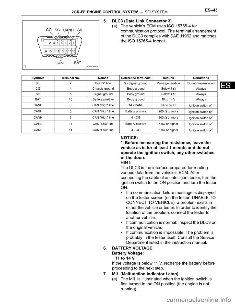
5. DLC3 (Data Link Connector 3)
(a) The vehicle's ECM uses ISO 15765-4 for
communication protocol. The terminal arrangement
of the DLC3 complies with SAE J1962 and matches
the ISO 15765-4 format.
NOTICE:
*: Before measuring the resistance, leave the
vehicle as is for at least 1 minute and do not
operate the ignition switch, any other switches
or the doors.
HINT:
The DLC3 is the interface prepared for reading
various data from the vehicle's ECM. After
connecting the cable of an intelligent tester, turn the
ignition switch to the ON position and turn the tester
ON.
• If a communication failure message is displayed
on the tester screen (on the tester: UNABLE TO
CONNECT TO VEHICLE), a problem exists in
either the vehicle or tester. In order to identify the
location of the problem, connect the tester to
another vehicle.
• If communication is normal: Inspect the DLC3 on
the original vehicle.
• If communication is impossible: The problem is
probably in the tester itself. Consult the Service
Department listed in the instruction manual.
6. BATTERY VOLTAGE
Battery Voltage:
11 to 14 V
If the voltage is below 11 V, recharge the battery before
proceeding to the next step.
7. MIL (Malfunction Indicator Lamp)
(a) The MIL is illuminated when the ignition switch is
first turned to the ON position (the engine is not
running).
H100769E16
Symbols Terminal No. Names Reference terminals Results Conditions
SIL 7 Bus "+" line 5 - Signal ground Pulse generation During transmission
CG 4 Chassis ground Body ground Below 1
Always
SG 5 Signal ground Body ground Below 1
Always
BAT 16 Battery positive Body ground 10 to 14 V Always
CANH 6 CAN "High" line 14 - CANL 54 to 69
Ignition switch off*
CANH 6 CAN "High" line Battery positive 200 or more
Ignition switch off*
CANH 6 CAN "High" line 4 - CG 200 or more
Ignition switch off*
CANL 14 CAN "Low" line Battery positive 6 k or higher
Ignition switch off*
CANL 14 CAN "Low" line 4 - CG 6 k or higher
Ignition switch off*