2007 TOYOTA SIENNA check engine
[x] Cancel search: check enginePage 53 of 3000

INTRODUCTION – HOW TO TROUBLESHOOT ECU CONTROLLED SYSTEMSIN–41
IN
If a DTC was displayed in the initial DTC check, the
problem may have occurred in a wire harness or
connector in that circuit in the past. Check the wire
harness and connectors.
B
A
The problem still occurs in a place other than the diagnostic
circuit (the DTC displayed first is either for a past problem or
a secondary problem).
4. SYMPTOM SIMULATION
HINT:
The most difficult case in troubleshooting is when no
problem symptoms occur. In such a case, a thorough
problem analysis must be carried out. A simulation of the
same or similar conditions and environment in which the
problem occurred in the customer's vehicle should be
carried out. No matter how much skill or experience a
technician has, troubleshooting without confirming the
problem symptoms will lead to important repairs being
overlooked and mistakes or delays.
For example:
With a problem that only occurs when the engine is
cold or as a result of vibration caused by the road
during driving, the problem can never be
determined if the symptoms are being checked on
a stationary vehicle or a vehicle with a warmed-up
engine. Vibration, heat or water penetration
(moisture) is difficult to reproduce. The symptom
simulation tests below are effective substitutes for
the conditions and can be applied on a stationary
vehicle. Important points in the symptom
simulation test:
In the symptom simulation test, the problem
symptoms as well as the problem area or parts
must be confirmed. First, narrow down the
possible problem circuits according to the
symptoms. Then, connect the tester and carry out
the symptom simulation test, judging whether the
circuit being tested is defective or normal. Also,
confirm the problem symptoms at the same time.
Refer to the problem symptoms table for each
system to narrow down the possible causes.SYSTEM NORMAL
TROUBLESHOOTING OF EACH PROBLEM SYMPTOM
Page 54 of 3000

IN–42INTRODUCTION – HOW TO TROUBLESHOOT ECU CONTROLLED SYSTEMS
IN
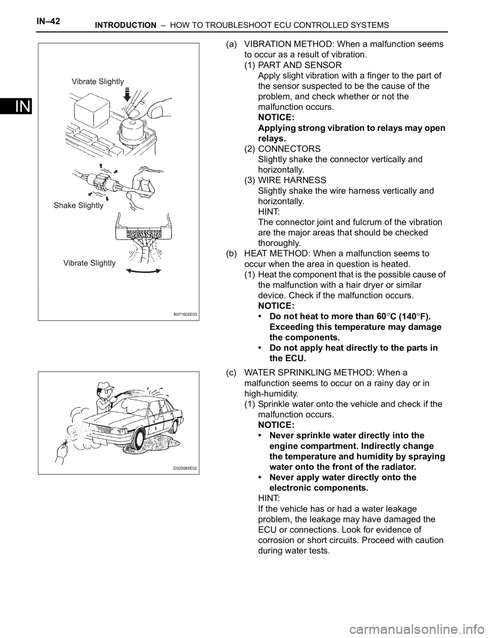
(a) VIBRATION METHOD: When a malfunction seems
to occur as a result of vibration.
(1) PART AND SENSOR
Apply slight vibration with a finger to the part of
the sensor suspected to be the cause of the
problem, and check whether or not the
malfunction occurs.
NOTICE:
Applying strong vibration to relays may open
relays.
(2) CONNECTORS
Slightly shake the connector vertically and
horizontally.
(3) WIRE HARNESS
Slightly shake the wire harness vertically and
horizontally.
HINT:
The connector joint and fulcrum of the vibration
are the major areas that should be checked
thoroughly.
(b) HEAT METHOD: When a malfunction seems to
occur when the area in question is heated.
(1) Heat the component that is the possible cause of
the malfunction with a hair dryer or similar
device. Check if the malfunction occurs.
NOTICE:
• Do not heat to more than 60
C (140F).
Exceeding this temperature may damage
the components.
• Do not apply heat directly to the parts in
the ECU.
(c) WATER SPRINKLING METHOD: When a
malfunction seems to occur on a rainy day or in
high-humidity.
(1) Sprinkle water onto the vehicle and check if the
malfunction occurs.
NOTICE:
• Never sprinkle water directly into the
engine compartment. Indirectly change
the temperature and humidity by spraying
water onto the front of the radiator.
• Never apply water directly onto the
electronic components.
HINT:
If the vehicle has or had a water leakage
problem, the leakage may have damaged the
ECU or connections. Look for evidence of
corrosion or short circuits. Proceed with caution
during water tests.B071602E03
D025085E02
Page 58 of 3000

INTRODUCTION – TERMSIN–51
IN
IFI Indirect Fuel Injection Indirect Injection (IDL)
IFS Inertia Fuel-Shutoff -
ISC Idle Speed Control -
KS Knock Sensor Knock Sensor
MAF Mass Airflow Air Flow Meter
MAP Manifold Absolute Pressure Manifold Pressure Intake Vacuum
MC Mixture ControlElectric Bleed Air Control Valve (EBCV)
Mixture Control Valve (MCV)
Electric Air Control Valve (EACV)
MDP Manifold Differential Pressure -
MFI Multiport Fuel Injection Electronic Fuel Injection (EFI)
MIL Malfunction Indicator Light Check Engine Light
MST Manifold Surface Temperature -
MVZ Manifold Vacuum Zone -
NVRAM Non-Volatile Random Access Memory -
O2S Oxygen SensorOxygen Sensor, O
2 Sensor (O2S)
OBD On-Board Diagnostic On-Board Diagnostic System (OBD)
OC Oxidation Catalytic Converter Oxidation Catalytic Convert (OC), CCo
OL Open Loop Open Loop
PAIR Pulsed Secondary Air Injection Air Suction (AS)
PCM Powertrain Control Module -
PNP Park/Neutral Position -
PROM Programmable Read Only Memory -
PSP Power Steering Pressure -
PTOX Periodic Trap OxidizerDiesel Particulate Filter (DPF)
Diesel Particulate Trap (DPT)
RAM Random Access Memory Random Access Memory (RAM)
RM Relay Module -
ROM Read Only Memory Read Only Memory (ROM)
RPM Engine Speed Engine Speed
SC Supercharger Supercharger
SCB Supercharger Bypass E-ABV
SFI Sequential Multiport Fuel Injection Electronic Fuel Injection (EFI), Sequential Injection
SPL Smoke Puff Limiter -
SRI Service Reminder Indicator -
SRT System Readiness Test -
ST Scan Tool -
TB Throttle Body Throttle Body
TBI Throttle Body Fuel InjectionSingle Point Injection
Central Fuel Injection (Ci)
TC Turbocharger Turbocharger
TCC Torque Converter Clutch Torque Converter
TCM Transmission Control Module Transmission ECU, ECT ECU
TP Throttle Position Throttle Position
TR Transmission Range -
TVV Thermal Vacuum ValveBimetallic Vacuum Switching Valve (BVSV)
Thermostatic Vacuum Switching Valve (TVSV)
TWC Three-Way Catalytic ConverterThree-Way Catalytic (TWC)
Manifold Converter
CC
RO
SAE
ABBREVIATIONSSAE TERMSTOYOTA TERMS
( )-ABBREVIATIONS
Page 61 of 3000

INTRODUCTION – HOW TO TROUBLESHOOT ECU CONTROLLED SYSTEMSIN–31
IN
ELECTRONIC CIRCUIT INSPECTION
PROCEDURE
1. BASIC INSPECTION
(a) WHEN MEASURING RESISTANCE OF
ELECTRONIC PARTS
(1) Unless otherwise stated, all resistance
measurements should be made at an ambient
temperature of 20
C (68F). Resistance
measurements may be inaccurate if measured
at high temperatures, i.e. immediately after the
vehicle has been running. Measurements should
be made after the engine has cooled down.
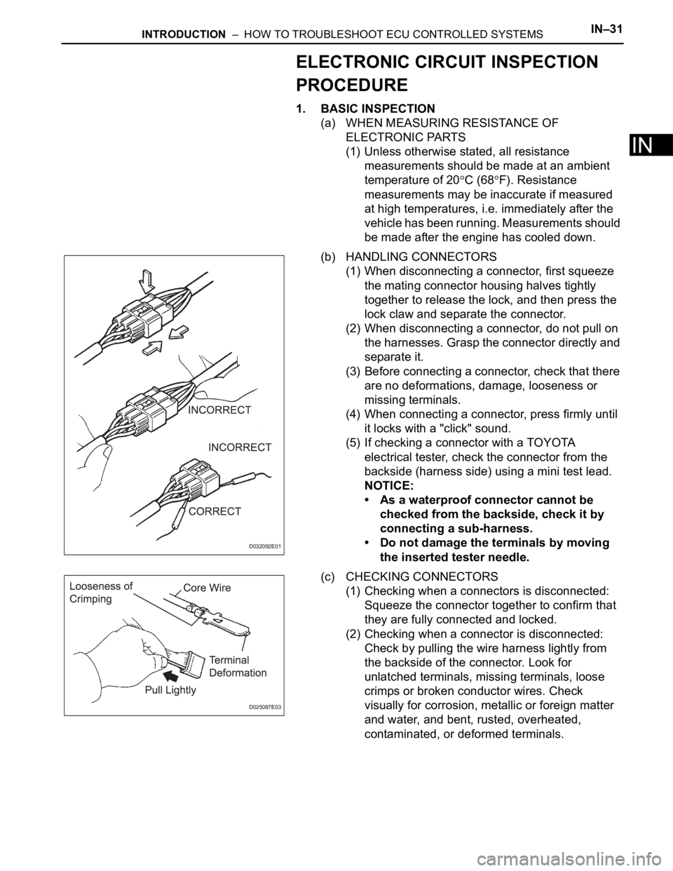
(b) HANDLING CONNECTORS
(1) When disconnecting a connector, first squeeze
the mating connector housing halves tightly
together to release the lock, and then press the
lock claw and separate the connector.
(2) When disconnecting a connector, do not pull on
the harnesses. Grasp the connector directly and
separate it.
(3) Before connecting a connector, check that there
are no deformations, damage, looseness or
missing terminals.
(4) When connecting a connector, press firmly until
it locks with a "click" sound.
(5) If checking a connector with a TOYOTA
electrical tester, check the connector from the
backside (harness side) using a mini test lead.
NOTICE:
• As a waterproof connector cannot be
checked from the backside, check it by
connecting a sub-harness.
• Do not damage the terminals by moving
the inserted tester needle.
(c) CHECKING CONNECTORS
(1) Checking when a connectors is disconnected:
Squeeze the connector together to confirm that
they are fully connected and locked.
(2) Checking when a connector is disconnected:
Check by pulling the wire harness lightly from
the backside of the connector. Look for
unlatched terminals, missing terminals, loose
crimps or broken conductor wires. Check
visually for corrosion, metallic or foreign matter
and water, and bent, rusted, overheated,
contaminated, or deformed terminals.
D032092E01
D025087E03
Page 64 of 3000

IN–34INTRODUCTION – HOW TO TROUBLESHOOT ECU CONTROLLED SYSTEMS
IN
3. CHECK FOR SHORT CIRCUIT
(a) If the wire harness is ground shorted (Fig. 5), locate
the section by conducting a resistance check with
the body ground (below).
(b) Check the resistance with the body ground.
(1) Disconnect connectors A and C and measure
the resistance.
Standard resistance (Fig. 6)
HINT:
Measure the resistance while lightly shaking the
wire harness vertically and horizontally. If your
results match the examples above, an open
circuit exists between terminal 1 of connector A
and terminal 1 of connector C.
(2) Disconnect connector B and measure the
resistance.
Standard resistance (Fig. 7)
If the results match the examples above, a short
circuit exists between terminal 1 of connector B2
and terminal 1 of connector C.
4. CHECK AND REPLACE ECU
NOTICE:
• The connector should not be disconnected from
the ECU. Perform the inspection from the
backside of the connector on the wire harness
side.
• When no measuring condition is specified,
perform the inspection with the engine stopped
and the ignition switch on.
• Check that the connectors are fully seated. Check
for loose, corroded or broken wires.
Z017008E02
Z017009E02
Tester Connection Specified Condition
Connector A terminal 1 - Body
groundBelow 1
Connector A terminal 2 - Body
ground10 k or higher
Z017808E02
Tester Connection Specified Condition
Connector A terminal 1 - Body
ground10 k
or higher
Connector B2 terminal 2 - Body
ground Below 1
Page 66 of 3000

IN–36INTRODUCTION – HOW TO TROUBLESHOOT ECU CONTROLLED SYSTEMS
IN
HOW TO PROCEED WITH
TROUBLESHOOTING
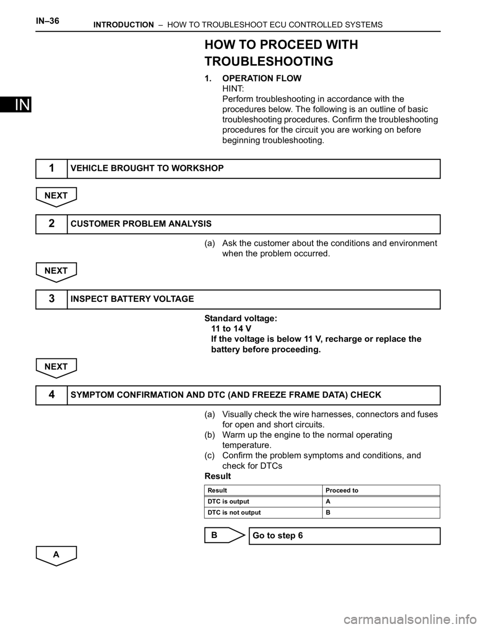
1. OPERATION FLOW
HINT:
Perform troubleshooting in accordance with the
procedures below. The following is an outline of basic
troubleshooting procedures. Confirm the troubleshooting
procedures for the circuit you are working on before
beginning troubleshooting.
NEXT
(a) Ask the customer about the conditions and environment
when the problem occurred.
NEXT
Standard voltage:
11 to 14 V
If the voltage is below 11 V, recharge or replace the
battery before proceeding.
NEXT
(a) Visually check the wire harnesses, connectors and fuses
for open and short circuits.
(b) Warm up the engine to the normal operating
temperature.
(c) Confirm the problem symptoms and conditions, and
check for DTCs
Result
B
A
1VEHICLE BROUGHT TO WORKSHOP
2CUSTOMER PROBLEM ANALYSIS
3INSPECT BATTERY VOLTAGE
4SYMPTOM CONFIRMATION AND DTC (AND FREEZE FRAME DATA) CHECK
Result Proceed to
DTC is output A
DTC is not output B
Go to step 6
Page 69 of 3000

INTRODUCTION – HOW TO TROUBLESHOOT ECU CONTROLLED SYSTEMSIN–39
IN
• In the DTC check, it is very important to determine
whether the problem indicated by the DTC either: 1)
still occurs, or 2) occurred in the past but has returned
to normal. In addition, the DTC should be compared
to the problem symptom to see if they are related. For
this reason, DTCs should be checked before and after
confirmation of symptoms (i.e., whether or not
problem symptoms exist) to determine current system
conditions, as shown in the flowchart below.
• Never skip the DTC check. Failing to check DTCs
may, depending on the case, result in unnecessary
troubleshooting for systems operating normally or
lead to repairs not related to the problem. Follow the
procedures listed in the flowchart in the correct order.
Theft Deterrent System XXXXX
Engine Immobiliser System
XX
Cruise Control SystemXXX
Dynamic Laser Cruise Control System
XXX
Lighting System
XX
Wiper and Washer SystemXXXXX
Power Door Lock Control System X X X
Wireless Door Lock Control SystemXX
Key Reminder Warning System X X XX
Meter / Gauge System X X X
Audio and Visual SystemXXXX
Rear Seat Entertainment System XXXXX
Navigation System
XXXX
Clearance Sonar SystemXXXXX
Rear View Monitor System XXXXX
Power Window Control System (with Jam
Protection Function)XXX
Power Window Control System (without Jam
Protection Function)XXXXX
Power Mirror Control System (with Memory) X X X
Power Mirror Control System (without Memory)XXXXX
Front Power Seat Control System X X X
Rear No. 2 Seat Assembly (with Power Stowing
Function)XXXXX
Window Deogger SystemXXXXX
Power Slide Door System
XX
Slide Door Closer System X X X
Back Door Closer SystemXX
Power Back Door SystemXX
Sliding Roof System XXXXX
Multiplex Communication System XXXXX
CAN Communication System XXXXXSystemSYMPTOM CONFIRMATION AND DIAGNOSTIC TROUBLE CODE
DTC Check
(Normal Mode)DTC Check
(Check Mode)Sensor Check/
Test Mode
(Input Signal
Check)Data List Active Test
Page 71 of 3000

INTRODUCTION – HOW TO TROUBLESHOOT ECU CONTROLLED SYSTEMSIN–41
IN
If a DTC was displayed in the initial DTC check, the
problem may have occurred in a wire harness or
connector in that circuit in the past. Check the wire
harness and connectors.
B
A
The problem still occurs in a place other than the diagnostic
circuit (the DTC displayed first is either for a past problem or
a secondary problem).
4. SYMPTOM SIMULATION
HINT:
The most difficult case in troubleshooting is when no
problem symptoms occur. In such a case, a thorough
problem analysis must be carried out. A simulation of the
same or similar conditions and environment in which the
problem occurred in the customer's vehicle should be
carried out. No matter how much skill or experience a
technician has, troubleshooting without confirming the
problem symptoms will lead to important repairs being
overlooked and mistakes or delays.
For example:
With a problem that only occurs when the engine is
cold or as a result of vibration caused by the road
during driving, the problem can never be
determined if the symptoms are being checked on
a stationary vehicle or a vehicle with a warmed-up
engine. Vibration, heat or water penetration
(moisture) is difficult to reproduce. The symptom
simulation tests below are effective substitutes for
the conditions and can be applied on a stationary
vehicle. Important points in the symptom
simulation test:
In the symptom simulation test, the problem
symptoms as well as the problem area or parts
must be confirmed. First, narrow down the
possible problem circuits according to the
symptoms. Then, connect the tester and carry out
the symptom simulation test, judging whether the
circuit being tested is defective or normal. Also,
confirm the problem symptoms at the same time.
Refer to the problem symptoms table for each
system to narrow down the possible causes.SYSTEM NORMAL
TROUBLESHOOTING OF EACH PROBLEM SYMPTOM