Page 72 of 3000

IN–42INTRODUCTION – HOW TO TROUBLESHOOT ECU CONTROLLED SYSTEMS
IN
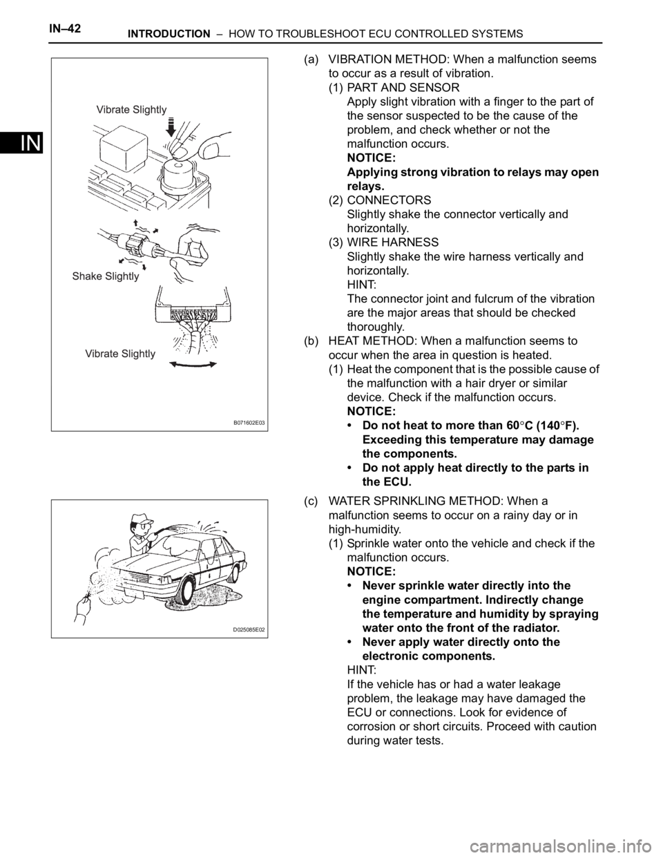
(a) VIBRATION METHOD: When a malfunction seems
to occur as a result of vibration.
(1) PART AND SENSOR
Apply slight vibration with a finger to the part of
the sensor suspected to be the cause of the
problem, and check whether or not the
malfunction occurs.
NOTICE:
Applying strong vibration to relays may open
relays.
(2) CONNECTORS
Slightly shake the connector vertically and
horizontally.
(3) WIRE HARNESS
Slightly shake the wire harness vertically and
horizontally.
HINT:
The connector joint and fulcrum of the vibration
are the major areas that should be checked
thoroughly.
(b) HEAT METHOD: When a malfunction seems to
occur when the area in question is heated.
(1) Heat the component that is the possible cause of
the malfunction with a hair dryer or similar
device. Check if the malfunction occurs.
NOTICE:
• Do not heat to more than 60
C (140F).
Exceeding this temperature may damage
the components.
• Do not apply heat directly to the parts in
the ECU.
(c) WATER SPRINKLING METHOD: When a
malfunction seems to occur on a rainy day or in
high-humidity.
(1) Sprinkle water onto the vehicle and check if the
malfunction occurs.
NOTICE:
• Never sprinkle water directly into the
engine compartment. Indirectly change
the temperature and humidity by spraying
water onto the front of the radiator.
• Never apply water directly onto the
electronic components.
HINT:
If the vehicle has or had a water leakage
problem, the leakage may have damaged the
ECU or connections. Look for evidence of
corrosion or short circuits. Proceed with caution
during water tests.B071602E03
D025085E02
Page 76 of 3000

2GR-FE COOLING – COOLING FAN SYSTEMCO–5
CO
ON-VEHICLE INSPECTION
1. INSPECT COOLING FAN SYSTEM
(a) Put the vehicle in the following conditions:
(1) The engine switch is off.
(2) The coolant temperature is less than 95
C
(203
F).
(3) The battery voltage is between 9 and 14 V.
(4) The A/C switch is OFF.
(b) Clamp the 400 A probe of an ammeter over the M+
wire of each cooling fan motor.
(c) Turn the ignition switch to the ON position and wait
for approximately 10 seconds. Check that the fan
stops.
(d) Start the engine. Check that the fan stops with the
engine idling.
HINT:
• Make sure that the radiator engine coolant
temperature is less than 95
C (203F).
• Turn the A/C switch OFF.
(e) Check that the fan operates when the A/C switch is
turned ON (MAX COOL and the magnetic clutch is
operating).
Standard current
HINT:
The coolant temperature is less than 95
C (203F).
(f) Check that the fan operates when the engine
coolant temperature sensor connector is
disconnected.
Standard current
Item Specified Condition
No. 1 cooling fan motor 5 to 14 A
No. 2 cooling fan motor 4 to 12 A
Item Specified Condition
No. 1 cooling fan motor 5 to 19 A
No. 2 cooling fan motor 4 to 16 A
Page 77 of 3000
CO–62GR-FE COOLING – COOLING FAN SYSTEM
CO
(g) After the engine is warmed up, check that the fan
operates as shown in the illustration.
HINT:
• The coolant temperature at which the fan starts
operating is approximately 95
C (203F).
• This system can also be checked using the
intelligent tester.
• Select the following menu items: Powertrain /
Engine / Data List / Initial Engine Coolant Temp.
A139339E05
Page 80 of 3000

IG–62GR-FE IGNITION – IGNITION COIL AND SPARK PLUG
IG
ON-VEHICLE INSPECTION
NOTICE:
In this section, the terms "cold" and "hot" refer to the
temperature of the coils. "Cold" means approximately -
10
C (14F) to 50C (122F). "Hot" means approximately
50
C (122F) to 100C (212F).
1. INSPECT IGNITION COIL ASSEMBLY
(a) Check for DTCs.
NOTICE:
If any DTC is present, perform troubleshooting
in accordance with the procedures for that DTC.
(b) Remove the ignition coil assembly and spark plug.
(See page IG-8).
(c) Check that sparks occur.
(1) Disconnect the 6 fuel injector connectors.
(2) Install the spark plugs to each ignition coil, and
connect the ignition coil connectors.
(3) Ground the spark plugs.
(4) Check if a spark occurs at each spark plug
while the engine is being cranked.
NOTICE:
• Be sure to ground the spark plugs when
checking.
• Replace the ignition coil if it receives an
impact.
• Do not crank the engine for more than 2
seconds.
(d) Perform the spark test according to the flowchart
below.
(1) Check that the ignition coil connector is
securely connected.
Result
(2) Perform a spark test on each ignition coil.
1. Replace the ignition coil with a normal one.
2. Perform the spark test again.
Result
A133895
A133897
Result Proceed to
NG Connect securely
OK Go to next step
Result Proceed to
NG Go to next step
OK Replace ignition coil
Page 81 of 3000

2GR-FE IGNITION – IGNITION COIL AND SPARK PLUGIG–7
IG
(3) Check the spark plug (See page EM-1).
Result
(4) Check the power supply to the ignition coil.
1. Turn the ignition switch to the ON position.
2. Check that there is battery voltage at the
ignition coil positive (+) terminal.
Result
(5) Measure the resistance of the crankshaft
position sensor (See page ES-514).
Result
(6) Check the IGT signal from the ECM (See page
ES-233)
Result
(e) Using a 16 mm (0.63 in.) plug wrench, install the
spark plugs.
Torque: 18 N*m (184 kgf*cm, 13 ft.*lbf)
(f) Connect the 6 fuel injector connectors.
(g) Install the ignition coil assembly (See page IG-10).
2. INSPECT SPARK PLUG
NOTICE:
• Never use a wire brush for cleaning.
• Never attempt to adjust the electrode gap on a
used spark plug.
(a) Check the electrode.
(1) Using a megohmmeter, measure the insulation
resistance.
Standard insulation resistance:
10 M
or higher
HINT:
• If the result is 10 M
or less, clean the plug
and measure the resistance again.
• If a megohmmeter is not available, perform
the following simple inspection instead.
(b) Alternative inspection method:
(1) Quickly accelerate the engine to 4000 rpm 5
times.
Result Proceed to
NG Replace spark plug
OK Go to next step
Result Proceed to
NGCheck wiring between ignition
switch and ignition coil
OK Go to next step
Result Proceed to
NG Replace crankshaft position sensor
OK Go to next step
Result Proceed to
NG Check ECM
OKRepair wiring between ignition coil
and ECM
I039522E10
Page 82 of 3000

IG–82GR-FE IGNITION – IGNITION COIL AND SPARK PLUG
IG
(2) Remove the spark plugs.
(3) Visually check the spark plug.
If the electrode is dry, the spark plug is
functioning properly. If the electrode is damp,
proceed to the next step.
(c) Check the spark plug for any damage to its threads
and insulator. If there is damage, replace the spark
plug.
Recommended spark plug
NOTICE:
Use only the listed spark plug or equivalent to
ensure engine performance and smooth
driveability.
(d) Check the spark plug electrode gap.
Maximum electrode gap for used spark plug:
1.4 mm (0.055 in.)
If the gap is greater than the maximum, replace the
spark plug.
Electrode gap for new spark plug:
1.0 to 1.1 mm (0.039 to 0.043 in.)
(e) Clean the spark plugs.
If the electrode has traces of wet carbon, clean the
electrode with a spark plug cleaner and then dry it.
Standard air pressure:
588 kPa (6 kgf*cm
2, 85 psi)
Standard duration:
20 seconds or less
HINT:
Only use the spark plug cleaner when the electrode
is free of oil. If the electrode has traces of oil, use
gasoline to clean off the oil before using the spark
plug cleaner.
(f) Install the ignition coil assembly and spark plug.
(See page IG-10).
Manufacturer Spark Plug Type
DENSO FK20HR11
A163282E01
B062019
Page 93 of 3000

AX–166U151E AUTOMATIC TRANSAXLE – AUTOMATIC TRANSAXLE ASSEMBLY
AX
INSTALLATION
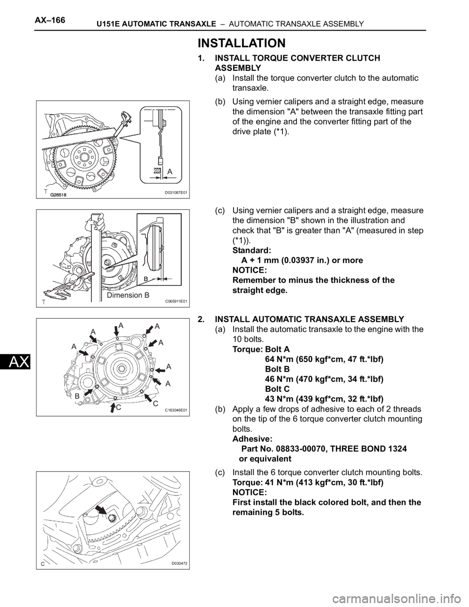
1. INSTALL TORQUE CONVERTER CLUTCH
ASSEMBLY
(a) Install the torque converter clutch to the automatic
transaxle.
(b) Using vernier calipers and a straight edge, measure
the dimension "A" between the transaxle fitting part
of the engine and the converter fitting part of the
drive plate (*1).
(c) Using vernier calipers and a straight edge, measure
the dimension "B" shown in the illustration and
check that "B" is greater than "A" (measured in step
(*1)).
Standard:
A + 1 mm (0.03937 in.) or more
NOTICE:
Remember to minus the thickness of the
straight edge.
2. INSTALL AUTOMATIC TRANSAXLE ASSEMBLY
(a) Install the automatic transaxle to the engine with the
10 bolts.
Torque: Bolt A
64 N*m (650 kgf*cm, 47 ft.*lbf)
Bolt B
46 N*m (470 kgf*cm, 34 ft.*lbf)
Bolt C
43 N*m (439 kgf*cm, 32 ft.*lbf)
(b) Apply a few drops of adhesive to each of 2 threads
on the tip of the 6 torque converter clutch mounting
bolts.
Adhesive:
Part No. 08833-00070, THREE BOND 1324
or equivalent
(c) Install the 6 torque converter clutch mounting bolts.
Torque: 41 N*m (413 kgf*cm, 30 ft.*lbf)
NOTICE:
First install the black colored bolt, and then the
remaining 5 bolts.
D031087E01
C065911E01
C163046E01
D030472
Page 103 of 3000

AX–168U151F AUTOMATIC TRANSAXLE – AUTOMATIC TRANSAXLE ASSEMBLY
AX
INSTALLATION
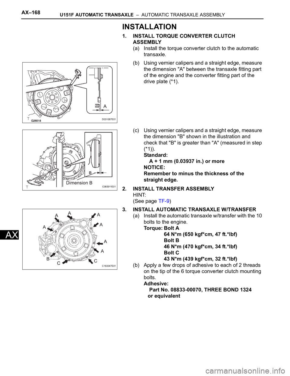
1. INSTALL TORQUE CONVERTER CLUTCH
ASSEMBLY
(a) Install the torque converter clutch to the automatic
transaxle.
(b) Using vernier calipers and a straight edge, measure
the dimension "A" between the transaxle fitting part
of the engine and the converter fitting part of the
drive plate (*1).
(c) Using vernier calipers and a straight edge, measure
the dimension "B" shown in the illustration and
check that "B" is greater than "A" (measured in step
(*1)).
Standard:
A + 1 mm (0.03937 in.) or more
NOTICE:
Remember to minus the thickness of the
straight edge.
2. INSTALL TRANSFER ASSEMBLY
HINT:
(See page TF-9)
3. INSTALL AUTOMATIC TRANSAXLE W/TRANSFER
(a) Install the automatic transaxle w/transfer with the 10
bolts to the engine.
To r q u e : B o l t A
64 N*m (650 kgf*cm, 47 ft.*lbf)
Bolt B
46 N*m (470 kgf*cm, 34 ft.*lbf)
Bolt C
43 N*m (439 kgf*cm, 32 ft.*lbf)
(b) Apply a few drops of adhesive to each of 2 threads
on the tip of the 6 torque converter clutch mounting
bolts.
Adhesive:
Part No. 08833-00070, THREE BOND 1324
or equivalent
D031087E01
C065911E01
C163047E01