Page 107 of 3000
TRANSFER – TRANSFER ASSEMBLYTF–9
TF
INSTALLATION
1. INSTALL TRANSFER ASSEMBLY
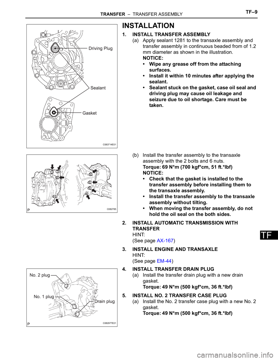
(a) Apply sealant 1281 to the transaxle assembly and
transfer assembly in continuous beaded from of 1.2
mm diameter as shown in the illustration.
NOTICE:
• Wipe any grease off from the attaching
surfaces.
• Install it within 10 minutes after applying the
sealant.
• Sealant stuck on the gasket, case oil seal and
driving plug may cause oil leakage and
seizure due to oil shortage. Care must be
taken.
(b) Install the transfer assembly to the transaxle
assembly with the 2 bolts and 6 nuts.
Torque: 69 N*m (700 kgf*cm, 51 ft.*lbf)
NOTICE:
• Check that the gasket is installed to the
transfer assembly before installing them to
the transaxle assembly.
• Install the transfer assembly to the transaxle
assembly without tilting.
• When moving the transfer assembly, do not
hold the oil seal on the both sides.
2. INSTALL AUTOMATIC TRANSMISSION WITH
TRANSFER
HINT:
(See page AX-167)
3. INSTALL ENGINE AND TRANSAXLE
HINT:
(See page EM-44)
4. INSTALL TRANSFER DRAIN PLUG
(a) Install the transfer drain plug with a new drain
gasket.
Torque: 49 N*m (500 kgf*cm, 36 ft.*lbf)
5. INSTALL NO. 2 TRANSFER CASE PLUG
(a) Install the No. 2 transfer case plug with a new No. 2
gasket.
Torque: 49 N*m (500 kgf*cm, 36 ft.*lbf)
C083714E01
C082785
C082977E01
Page 180 of 3000
BC–4BRAKE CONTROL – ANTI-LOCK BRAKE SYSTEM
BC
TEST MODE PROCEDURE
1. SPEED SENSOR SIGNAL CHECK (WHEN USING SST
CHECK WIRE):
HINT:
• If the ignition switch is turned from the ON to the ACC
or LOCK position during Test Mode, the DTCs of the
signal check function will be erased.
(a) Turn the ignition switch off.
(b) Check that the steering wheel is in the straight-
ahead position and move the shift lever to the P
position (Automatic Transmission) or apply the
parking brake (Manual Transmission).
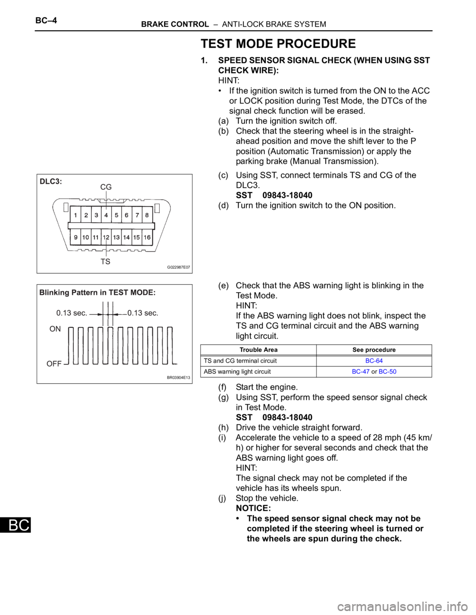
(c) Using SST, connect terminals TS and CG of the
DLC3.
SST 09843-18040
(d) Turn the ignition switch to the ON position.
(e) Check that the ABS warning light is blinking in the
Test Mode.
HINT:
If the ABS warning light does not blink, inspect the
TS and CG terminal circuit and the ABS warning
light circuit.
(f) Start the engine.
(g) Using SST, perform the speed sensor signal check
in Test Mode.
SST 09843-18040
(h) Drive the vehicle straight forward.
(i) Accelerate the vehicle to a speed of 28 mph (45 km/
h) or higher for several seconds and check that the
ABS warning light goes off.
HINT:
The signal check may not be completed if the
vehicle has its wheels spun.
(j) Stop the vehicle.
NOTICE:
• The speed sensor signal check may not be
completed if the steering wheel is turned or
the wheels are spun during the check.
G022987E07
BR03904E13
Trouble Area See procedure
TS and CG terminal circuitBC-64
ABS warning light circuitBC-47 or BC-50
Page 183 of 3000
BRAKE CONTROL – ANTI-LOCK BRAKE SYSTEMBC–7
BC
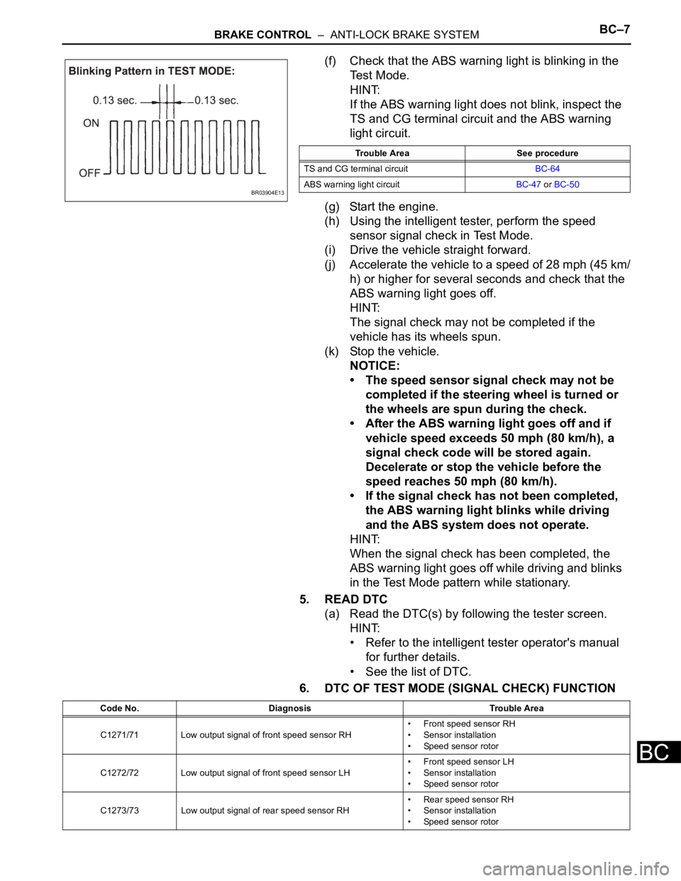
(f) Check that the ABS warning light is blinking in the
Test Mode.
HINT:
If the ABS warning light does not blink, inspect the
TS and CG terminal circuit and the ABS warning
light circuit.
(g) Start the engine.
(h) Using the intelligent tester, perform the speed
sensor signal check in Test Mode.
(i) Drive the vehicle straight forward.
(j) Accelerate the vehicle to a speed of 28 mph (45 km/
h) or higher for several seconds and check that the
ABS warning light goes off.
HINT:
The signal check may not be completed if the
vehicle has its wheels spun.
(k) Stop the vehicle.
NOTICE:
• The speed sensor signal check may not be
completed if the steering wheel is turned or
the wheels are spun during the check.
• After the ABS warning light goes off and if
vehicle speed exceeds 50 mph (80 km/h), a
signal check code will be stored again.
Decelerate or stop the vehicle before the
speed reaches 50 mph (80 km/h).
• If the signal check has not been completed,
the ABS warning light blinks while driving
and the ABS system does not operate.
HINT:
When the signal check has been completed, the
ABS warning light goes off while driving and blinks
in the Test Mode pattern while stationary.
5. READ DTC
(a) Read the DTC(s) by following the tester screen.
HINT:
• Refer to the intelligent tester operator's manual
for further details.
• See the list of DTC.
6. DTC OF TEST MODE (SIGNAL CHECK) FUNCTION
BR03904E13
Trouble Area See procedure
TS and CG terminal circuitBC-64
ABS warning light circuitBC-47 or BC-50
Code No. Diagnosis Trouble Area
C1271/71 Low output signal of front speed sensor RH• Front speed sensor RH
• Sensor installation
• Speed sensor rotor
C1272/72 Low output signal of front speed sensor LH• Front speed sensor LH
• Sensor installation
• Speed sensor rotor
C1273/73 Low output signal of rear speed sensor RH• Rear speed sensor RH
• Sensor installation
• Speed sensor rotor
Page 243 of 3000
ENGINE IMMOBILISER – ENGINE IMMOBILISER SYSTEMEI–3
EI
HOW TO PROCEED WITH
TROUBLESHOOTING
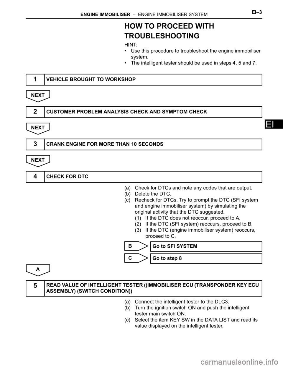
HINT:
• Use this procedure to troubleshoot the engine immobiliser
system.
• The intelligent tester should be used in steps 4, 5 and 7.
NEXT
NEXT
NEXT
(a) Check for DTCs and note any codes that are output.
(b) Delete the DTC.
(c) Recheck for DTCs. Try to prompt the DTC (SFI system
and engine immobiliser system) by simulating the
original activity that the DTC suggested.
(1) If the DTC does not reoccur, proceed to A.
(2) If the DTC (SFI system) reoccurs, proceed to B.
(3) If the DTC (engine immobiliser system) reoccurs,
proceed to C.
B
C
A
(a) Connect the intelligent tester to the DLC3.
(b) Turn the ignition switch ON and push the intelligent
tester main switch ON.
(c) Select the item KEY SW in the DATA LIST and read its
value displayed on the intelligent tester.
1VEHICLE BROUGHT TO WORKSHOP
2CUSTOMER PROBLEM ANALYSIS CHECK AND SYMPTOM CHECK
3CRANK ENGINE FOR MORE THAN 10 SECONDS
4CHECK FOR DTC
Go to SFI SYSTEM
Go to step 8
5READ VALUE OF INTELLIGENT TESTER ((IMMOBILISER ECU (TRANSPONDER KEY ECU
ASSEMBLY) (SWITCH CONDITION))
Page 312 of 3000
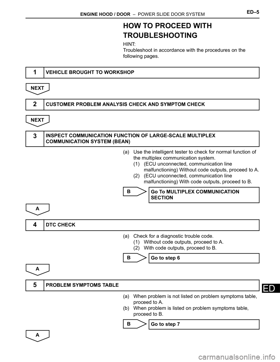
ENGINE HOOD / DOOR – POWER SLIDE DOOR SYSTEMED–5
ED
HOW TO PROCEED WITH
TROUBLESHOOTING
HINT:
Troubleshoot in accordance with the procedures on the
following pages.
NEXT
NEXT
(a) Use the intelligent tester to check for normal function of
the multiplex communication system.
(1) (ECU unconnected, communication line
malfunctioning) Without code outputs, proceed to A.
(2) (ECU unconnected, communication line
malfunctioning) With code outputs, proceed to B.
B
A
(a) Check for a diagnostic trouble code.
(1) Without code outputs, proceed to A.
(2) With code outputs, proceed to B.
B
A
(a) When problem is not listed on problem symptoms table,
proceed to A.
(b) When problem is listed on problem symptoms table,
proceed to B.
B
A
1VEHICLE BROUGHT TO WORKSHOP
2CUSTOMER PROBLEM ANALYSIS CHECK AND SYMPTOM CHECK
3INSPECT COMMUNICATION FUNCTION OF LARGE-SCALE MULTIPLEX
COMMUNICATION SYSTEM (BEAN)
Go To MULTIPLEX COMMUNICATION
SECTION
4DTC CHECK
Go to step 6
5PROBLEM SYMPTOMS TABLE
Go to step 7
Page 313 of 3000
ED–6ENGINE HOOD / DOOR – POWER SLIDE DOOR SYSTEM
ED
(a) Data List / Active Test (See page ED-22).
(b) Operation check (See page ED-6).
(c) Inspection.
(d) Terminals of ECU (See page ED-17).
NEXT
NEXT
NEXT
NEXT
6PERFORM TROUBLESHOOTING ACCORDING TO MALFUNCTION SYMPTOM
7ADJUST, REPAIR OR REPLACE
8RESET POWER SLIDE DOOR SYSTEM
9CONFIRMATION TEST
END
Page 314 of 3000
ES–102GR-FE ENGINE CONTROL SYSTEM – SFI SYSTEM
ES
HOW TO PROCEED WITH
TROUBLESHOOTING
HINT:
The intelligent tester can be used in steps 2, 3, 4, 6 and 9.
NEXT
HINT:
If the display indicates a communication fault in the tester,
inspect the DLC3.
NEXT
(a) Check for DTC(s) and freeze frame data (See page ES-
40).
HINT:
Record or print the DTCs and freeze frame data, if
necessary.
NEXT
(a) Clear the DTC(s) and freeze frame data (See page ES-
40).
NEXT
NEXT
(a) Set the check mode (See page ES-43).
NEXT
HINT:
If the engine does not start, perform steps 9 and 11 first.
1VEHICLE BROUGHT TO WORKSHOP
2CONNECT INTELLIGENT TESTER TO DLC3
3CHECK DTC AND FREEZE FRAME DATA
4CLEAR DTC AND FREEZE FRAME DATA
5CONDUCT VISUAL INSPECTION
6SET CHECK MODE DIAGNOSIS
7CONFIRM PROBLEM SYMPTOMS
Page 315 of 3000
2GR-FE ENGINE CONTROL SYSTEM – SFI SYSTEMES–11
ES
Result
B
A
NEXT
(a) Check for DTCs (See page ES-39).
Result
B
A
HINT:
Refer to the DTC chart (See page ES-56).
NEXT
HINT:
Refer to "BASIC INSPECTION" (See page ES-13).
Result
B
A
Result Proceed to
Malfunction does not occur A
Malfunction occurs B
GO TO STEP 9
8SIMULATE SYMPTOMS
9CHECK FOR DTCS
Result Proceed to
Trouble code A
No code B
GO TO STEP 11
10REFER TO DTC CHART
GO TO STEP 13
11CONDUCT BASIC INSPECTION
Result Proceed to
Malfunctioning parts not confirmed A
Malfunctioning parts confirmed B
GO TO STEP 16