Page 182 of 3000

BC–6BRAKE CONTROL – ANTI-LOCK BRAKE SYSTEM
BC
HINT:
The codes in this table are output only in Test Mode
(signal check).
4. SPEED SENSOR SIGNAL CHECK (WHEN USING
INTELLIGENT TESTER):
HINT:
• If the ignition switch is turned from the ON to the ACC
or LOCK position during Test Mode, DTCs of the
signal check function will be erased.
• During Test Mode, the ECU records all DTCs of the
signal check function. By performing the signal check,
the codes are erased if normality is confirmed. The
remaining codes are the codes where an abnormality
was found.
(a) Turn the ignition switch off.
(b) Check that the steering wheel is in the straight-
ahead position.
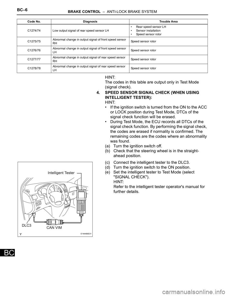
(c) Connect the intelligent tester to the DLC3.
(d) Turn the ignition switch to the ON position.
(e) Set the intelligent tester to Test Mode (select
"SIGNAL CHECK").
HINT:
Refer to the intelligent tester operator's manual for
further details.
C1274/74 Low output signal of rear speed sensor LH• Rear speed sensor LH
• Sensor installation
• Speed sensor rotor
C1275/75Abnormal change in output signal of front speed sensor
RHSpeed sensor rotor
C1276/76Abnormal change in output signal of front speed sensor
LHSpeed sensor rotor
C1277/77Abnormal change in output signal of rear speed sensor
RHSpeed sensor rotor
C1278/78Abnormal change in output signal of rear speed sensor
LHSpeed sensor rotor Code No. Diagnosis Trouble Area
E144486E01
Page 183 of 3000

BRAKE CONTROL – ANTI-LOCK BRAKE SYSTEMBC–7
BC
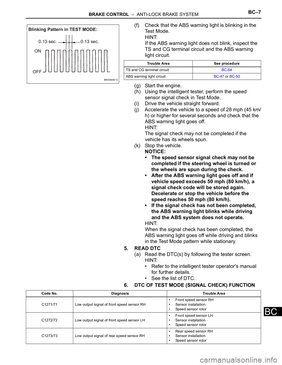
(f) Check that the ABS warning light is blinking in the
Test Mode.
HINT:
If the ABS warning light does not blink, inspect the
TS and CG terminal circuit and the ABS warning
light circuit.
(g) Start the engine.
(h) Using the intelligent tester, perform the speed
sensor signal check in Test Mode.
(i) Drive the vehicle straight forward.
(j) Accelerate the vehicle to a speed of 28 mph (45 km/
h) or higher for several seconds and check that the
ABS warning light goes off.
HINT:
The signal check may not be completed if the
vehicle has its wheels spun.
(k) Stop the vehicle.
NOTICE:
• The speed sensor signal check may not be
completed if the steering wheel is turned or
the wheels are spun during the check.
• After the ABS warning light goes off and if
vehicle speed exceeds 50 mph (80 km/h), a
signal check code will be stored again.
Decelerate or stop the vehicle before the
speed reaches 50 mph (80 km/h).
• If the signal check has not been completed,
the ABS warning light blinks while driving
and the ABS system does not operate.
HINT:
When the signal check has been completed, the
ABS warning light goes off while driving and blinks
in the Test Mode pattern while stationary.
5. READ DTC
(a) Read the DTC(s) by following the tester screen.
HINT:
• Refer to the intelligent tester operator's manual
for further details.
• See the list of DTC.
6. DTC OF TEST MODE (SIGNAL CHECK) FUNCTION
BR03904E13
Trouble Area See procedure
TS and CG terminal circuitBC-64
ABS warning light circuitBC-47 or BC-50
Code No. Diagnosis Trouble Area
C1271/71 Low output signal of front speed sensor RH• Front speed sensor RH
• Sensor installation
• Speed sensor rotor
C1272/72 Low output signal of front speed sensor LH• Front speed sensor LH
• Sensor installation
• Speed sensor rotor
C1273/73 Low output signal of rear speed sensor RH• Rear speed sensor RH
• Sensor installation
• Speed sensor rotor
Page 189 of 3000

STEERING COLUMN – STEERING SYSTEMSR–3
SR
REPAIR
1. STEERING OFF CENTER REPAIR PROCEDURE
(a) Inspect steering wheel off center.
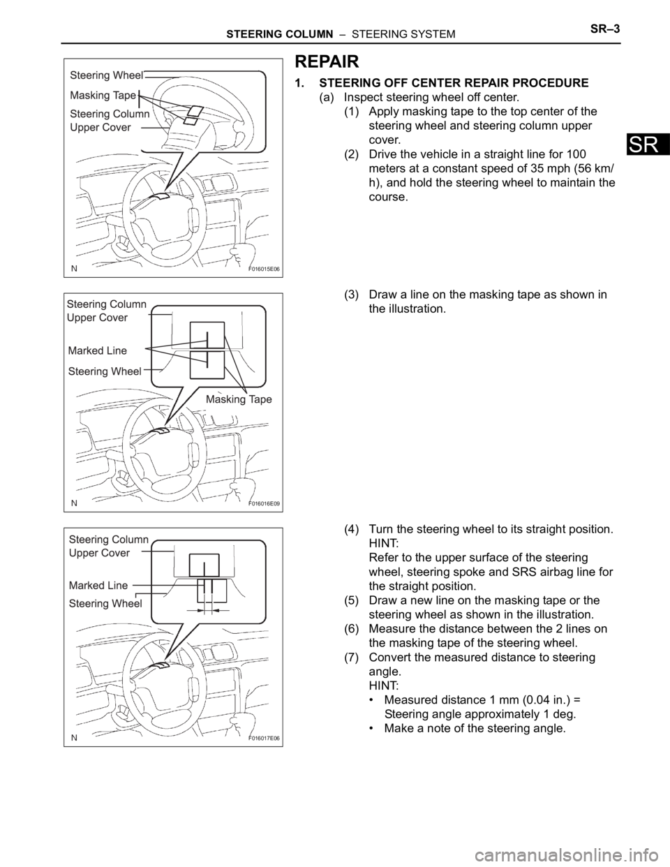
(1) Apply masking tape to the top center of the
steering wheel and steering column upper
cover.
(2) Drive the vehicle in a straight line for 100
meters at a constant speed of 35 mph (56 km/
h), and hold the steering wheel to maintain the
course.
(3) Draw a line on the masking tape as shown in
the illustration.
(4) Turn the steering wheel to its straight position.
HINT:
Refer to the upper surface of the steering
wheel, steering spoke and SRS airbag line for
the straight position.
(5) Draw a new line on the masking tape or the
steering wheel as shown in the illustration.
(6) Measure the distance between the 2 lines on
the masking tape of the steering wheel.
(7) Convert the measured distance to steering
angle.
HINT:
• Measured distance 1 mm (0.04 in.) =
Steering angle approximately 1 deg.
• Make a note of the steering angle.
F016015E06
F016016E09
F016017E06
Page 190 of 3000
SR–4STEERING COLUMN – STEERING SYSTEM
SR
(b) Adjust the steering angle.
(1) Draw a line on the RH and LH tie rod and on
the RH and LH rack end, which can easily be
seen.
(2) Using a paper gauge, measure the distance
from the RH and LH tie rod ends to the rack
end screws.
HINT:
• Measure the RH side and LH side.
• Make a note of the measured values.
(3) Remove the RH and LH boot clips from the
rack boots.
(4) Loosen the RH and LH lock nuts.
(5) Turn the RH and LH rack end by the same
amount (but in different directions) according to
the steering angle.
HINT:
1 turn 360 deg. of rack end (1.5 mm (0.059 in.)
horizontal movement) - 12 deg. of steering
angle.
(6) Tighten the RH and LH lock nuts.
Torque: 74 N*m (755 kgf*cm, 55 ft.*lbf)
NOTICE:
Make sure that the difference in length
between RH and LH tie rod ends and rack
end screws are within 1.5 mm (0.059 in.).
(7) Install the RH and LH boot clips.
R000429E08
F016018
Page 191 of 3000
POWER STEERING – VANE PUMPPS–9
PS
REMOVAL
1. DRAIN POWER STEERING FLUID
2. REMOVE FRONT WHEEL RH
3. REMOVE FRONT FENDER APRON SEAL RH (See
page EM-26)
4. REMOVE FAN AND GENERATOR V BELT (See page
EM-6)
5. DISCONNECT NO. 1 FLUID RESERVOIR TO PUMP
HOSE
(a) Slide the clip and disconnect the No. 1 fluid
reservoir to pump hose from the vane pump
assembly.
6. DISCONNECT PRESSURE FEED TUBE ASSEMBLY
(a) Remove the union bolt and disconnect the pressure
feed tube assembly from the vane pump assembly.
(b) Remove the gasket from the pressure feed tube
assembly.
7. DISCONNECT POWER STEERING FLUID PRESSURE
SWITCH CONNECTOR
(a) Disconnect the power steering fluid pressure switch
connector.
C133174E02
C161546
C161547
Page 192 of 3000
PS–10POWER STEERING – VANE PUMP
PS
8. REMOVE VANE PUMP ASSEMBLY
(a) Using SST, loosen bolt (A) and remove bolt (B), and
then remove the vane pump assembly.
SST 09249-63010
(b) Remove the bolt from the vane pump assembly.
DISASSEMBLY
1. HOLD VANE PUMP ASSEMBLY
(a) Using SST, hold the vane pump assembly in a vise.
SST 09630-00014 (09631-00132)
2. REMOVE POWER STEERING SUCTION PORT UNION
(a) Remove the bolt and the power steering suction port
union from the vane pump front housing.
(b) Using a screwdriver, remove the O-ring from the
power steering suction port union.
3. REMOVE POWER STEERING FLUID PRESSURE
SWITCH
NOTICE:
Perform this procedure only when the power
steering fluid pressure switch is replaced.
C158999E01
C135238
C141305E01
C133179
Page 193 of 3000
POWER STEERING – VANE PUMPPS–11
PS
(a) Remove the power steering fluid pressure switch
from the vane pump front housing.
4. REMOVE FLOW CONTROL VALVE ASSEMBLY
(a) Remove the pressure port union from the vane
pump front housing.
(b) Remove the O-ring from the pressure port union.
(c) Remove the flow control valve assembly and the
flow control valve compression spring from the vane
pump front housing.
5. REMOVE VANE PUMP REAR HOUSING
(a) Remove the 4 bolts and vane pump rear housing
from the vane pump front housing.
(b) Using a screwdriver, remove the O-ring from the
vane pump rear housing.
HINT:
Tape the screwdriver tip before use.
6. REMOVE VANE PUMP SHAFT WITH PULLEY
(a) Using 2 screwdrivers, remove the vane pump shaft
snap ring from the vane pump shaft with pulley.
(b) Remove the vane pump shaft with pulley.
C133180
C158998
C107024
C107025E02
C057767
Page 194 of 3000
PS–12POWER STEERING – VANE PUMP
PS
7. REMOVE VANE PUMP ROTOR
(a) Remove the 10 vane pump plates.
(b) Remove the vane pump rotor.
8. REMOVE VANE PUMP CAM RING
(a) Remove the vane pump cam ring from the vane
pump front housing.
9. REMOVE VANE PUMP FRONT SIDE PLATE
(a) Remove the vane pump front side plate from the
vane pump front housing.
(b) Using a screwdriver, remove the O-ring from the
vane pump front side plate.
HINT:
Tape the screwdriver tip before use.
(c) Remove the O-ring from the vane pump front
housing.
C114697
C114698
C114699
C107029E02
C114700