Page 25 of 3000
EM–262GR-FE ENGINE MECHANICAL – ENGINE ASSEMBLY
EM
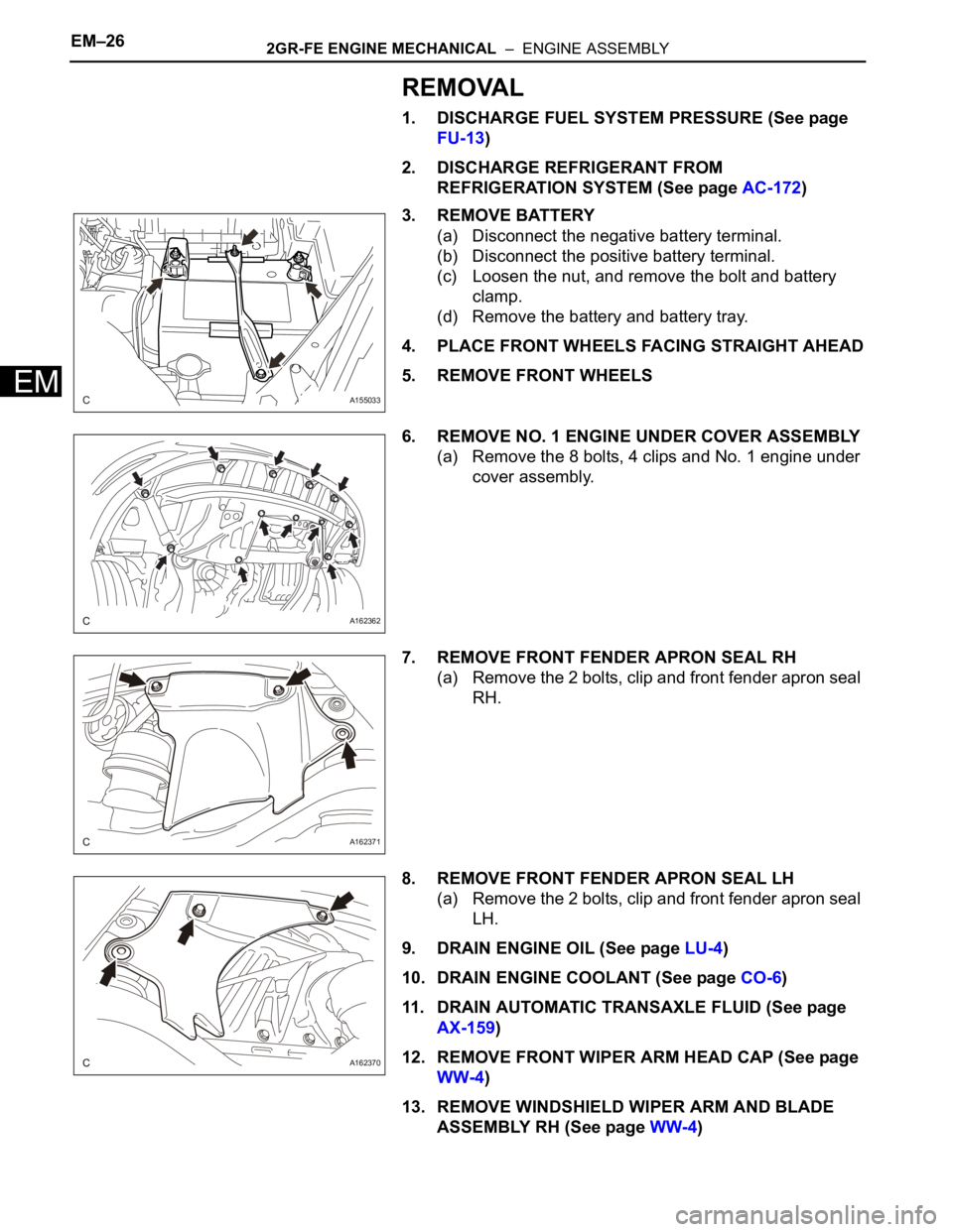
REMOVAL
1. DISCHARGE FUEL SYSTEM PRESSURE (See page
FU-13)
2. DISCHARGE REFRIGERANT FROM
REFRIGERATION SYSTEM (See page AC-172)
3. REMOVE BATTERY
(a) Disconnect the negative battery terminal.
(b) Disconnect the positive battery terminal.
(c) Loosen the nut, and remove the bolt and battery
clamp.
(d) Remove the battery and battery tray.
4. PLACE FRONT WHEELS FACING STRAIGHT AHEAD
5. REMOVE FRONT WHEELS
6. REMOVE NO. 1 ENGINE UNDER COVER ASSEMBLY
(a) Remove the 8 bolts, 4 clips and No. 1 engine under
cover assembly.
7. REMOVE FRONT FENDER APRON SEAL RH
(a) Remove the 2 bolts, clip and front fender apron seal
RH.
8. REMOVE FRONT FENDER APRON SEAL LH
(a) Remove the 2 bolts, clip and front fender apron seal
LH.
9. DRAIN ENGINE OIL (See page LU-4)
10. DRAIN ENGINE COOLANT (See page CO-6)
11. DRAIN AUTOMATIC TRANSAXLE FLUID (See page
AX-159)
12. REMOVE FRONT WIPER ARM HEAD CAP (See page
WW-4)
13. REMOVE WINDSHIELD WIPER ARM AND BLADE
ASSEMBLY RH (See page WW-4)
A155033
A162362
A162371
A162370
Page 191 of 3000
POWER STEERING – VANE PUMPPS–9
PS
REMOVAL
1. DRAIN POWER STEERING FLUID
2. REMOVE FRONT WHEEL RH
3. REMOVE FRONT FENDER APRON SEAL RH (See
page EM-26)
4. REMOVE FAN AND GENERATOR V BELT (See page
EM-6)
5. DISCONNECT NO. 1 FLUID RESERVOIR TO PUMP
HOSE
(a) Slide the clip and disconnect the No. 1 fluid
reservoir to pump hose from the vane pump
assembly.
6. DISCONNECT PRESSURE FEED TUBE ASSEMBLY
(a) Remove the union bolt and disconnect the pressure
feed tube assembly from the vane pump assembly.
(b) Remove the gasket from the pressure feed tube
assembly.
7. DISCONNECT POWER STEERING FLUID PRESSURE
SWITCH CONNECTOR
(a) Disconnect the power steering fluid pressure switch
connector.
C133174E02
C161546
C161547
Page 204 of 3000
AIR CONDITIONING – COMPRESSOR AND MAGNETIC CLUTCHAC–227
AC
REMOVAL
1. RECOVER REFRIGERANT FROM REFRIGERATION
SYSTEM (See page AC-172)
2. REMOVE FRONT WHEEL RH
3. REMOVE FRONT FENDER APRON SEAL RH (See
page EM-26)
4. REMOVE V-RIBBED BELT (See page EM-6)
5. REMOVE RADIATOR AND FAN ASSEMBLY
(See page CO-28)
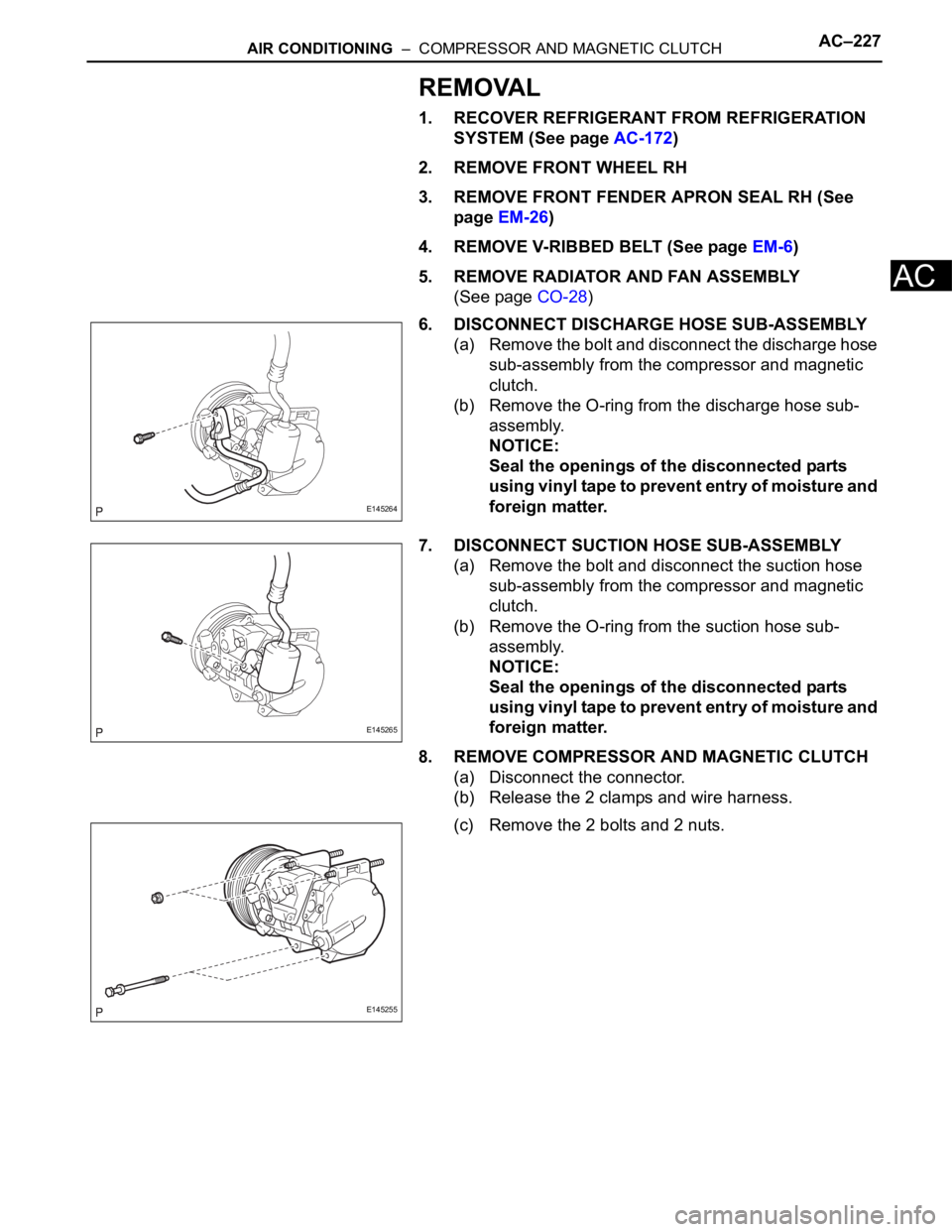
6. DISCONNECT DISCHARGE HOSE SUB-ASSEMBLY
(a) Remove the bolt and disconnect the discharge hose
sub-assembly from the compressor and magnetic
clutch.
(b) Remove the O-ring from the discharge hose sub-
assembly.
NOTICE:
Seal the openings of the disconnected parts
using vinyl tape to prevent entry of moisture and
foreign matter.
7. DISCONNECT SUCTION HOSE SUB-ASSEMBLY
(a) Remove the bolt and disconnect the suction hose
sub-assembly from the compressor and magnetic
clutch.
(b) Remove the O-ring from the suction hose sub-
assembly.
NOTICE:
Seal the openings of the disconnected parts
using vinyl tape to prevent entry of moisture and
foreign matter.
8. REMOVE COMPRESSOR AND MAGNETIC CLUTCH
(a) Disconnect the connector.
(b) Release the 2 clamps and wire harness.
(c) Remove the 2 bolts and 2 nuts.
E145264
E145265
E145255
Page 840 of 3000
EXTERIOR – FRONT BUMPERET–3
ET
REMOVAL
1. DISCONNECT CABLE FROM NEGATIVE BATTERY
TERMINAL
2. REMOVE FRONT BUMPER ASSEMBLY
(a) Remove the 4 screws and separate the fender liner
from the front bumper assembly.
(b) Remove the 8 screws and separate the engine
under cover from the front bumper assembly.
B125278
B125279
Page 841 of 3000
ET–4EXTERIOR – FRONT BUMPER
ET
(c) Remove the 5 clips.
(d) Disengage the claws on the left and right sides of
the front bumper and pull the front bumper toward
the front of the vehicle as shown in the illustration.
HINT:
• Apply protective tape to the bottom part of the
front fender to prevent it from being damaged.
• Disconnect the connectors if necessary.
B125280
B125281
Page 879 of 3000
EM–622GR-FE ENGINE MECHANICAL – ENGINE ASSEMBLY
EM
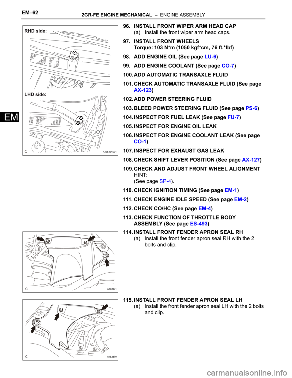
96. INSTALL FRONT WIPER ARM HEAD CAP
(a) Install the front wiper arm head caps.
97. INSTALL FRONT WHEELS
Torque: 103 N*m (1050 kgf*cm, 76 ft.*lbf)
98. ADD ENGINE OIL (See page LU-6)
99. ADD ENGINE COOLANT (See page CO-7)
100. ADD AUTOMATIC TRANSAXLE FLUID
101. CHECK AUTOMATIC TRANSAXLE FLUID (See page
AX-123)
102. ADD POWER STEERING FLUID
103. BLEED POWER STEERING FLUID (See page PS-6)
104. INSPECT FOR FUEL LEAK (See page FU-7)
105. INSPECT FOR ENGINE OIL LEAK
106. INSPECT FOR ENGINE COOLANT LEAK (See page
CO-1)
107. INSPECT FOR EXHAUST GAS LEAK
108. CHECK SHIFT LEVER POSITION (See page AX-127)
109. CHECK AND ADJUST FRONT WHEEL ALIGNMENT
HINT:
(See page SP-4).
110. CHECK IGNITION TIMING (See page EM-1)
111. CHECK ENGINE IDLE SPEED (See page EM-2)
112. CHECK CO/HC (See page EM-4)
113. CHECK FUNCTION OF THROTTLE BODY
ASSEMBLY (See page ES-493)
114. INSTALL FRONT FENDER APRON SEAL RH
(a) Install the front fender apron seal RH with the 2
bolts and clip.
115. INSTALL FRONT FENDER APRON SEAL LH
(a) Install the front fender apron seal LH with the 2 bolts
and clip.
A165364E01
A162371
A162370
Page 980 of 3000
EM–62GR-FE ENGINE MECHANICAL – DRIVE BELT
EM
REMOVAL
1. REMOVE FRONT WHEEL RH
2. REMOVE FRONT FENDER APRON SEAL RH (See
page EM-26)
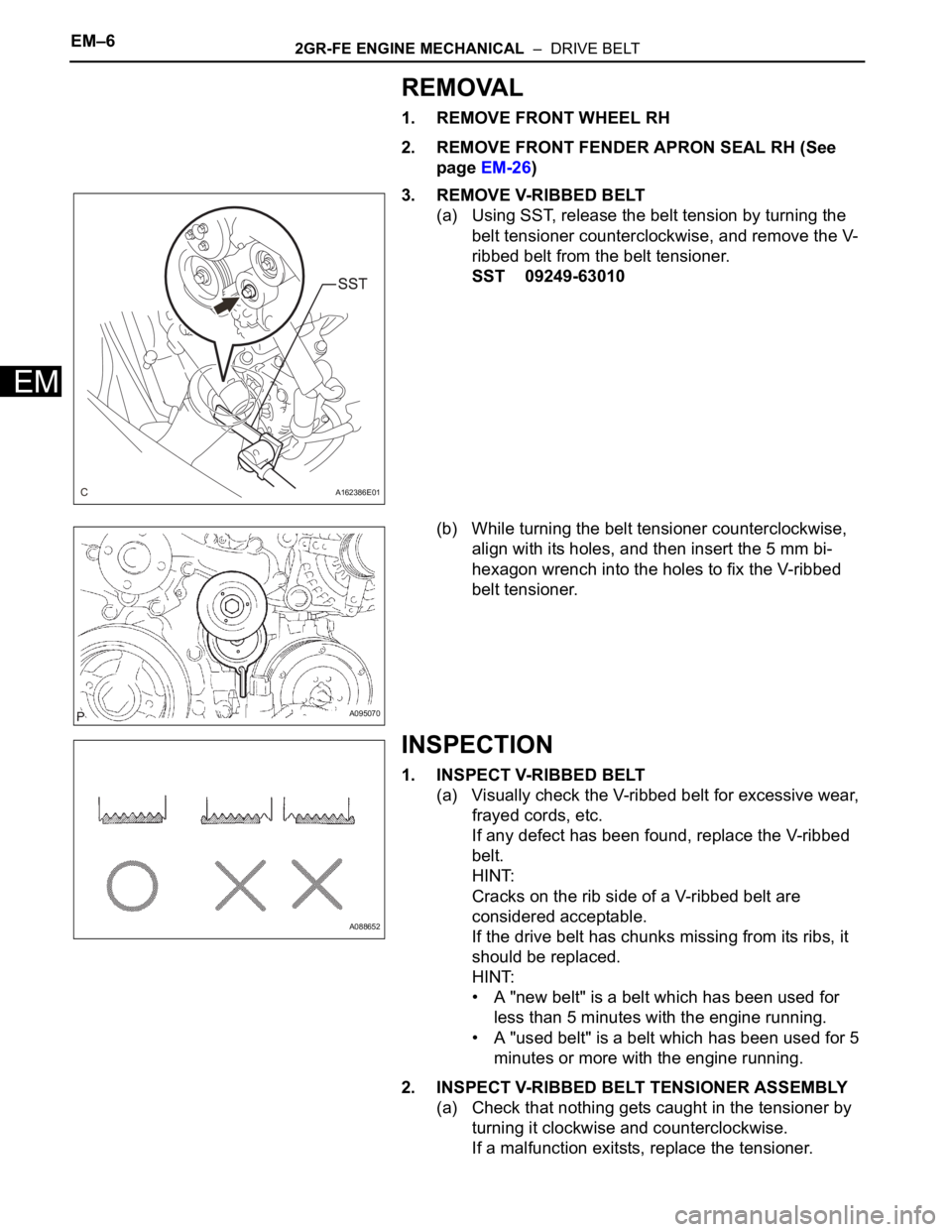
3. REMOVE V-RIBBED BELT
(a) Using SST, release the belt tension by turning the
belt tensioner counterclockwise, and remove the V-
ribbed belt from the belt tensioner.
SST 09249-63010
(b) While turning the belt tensioner counterclockwise,
align with its holes, and then insert the 5 mm bi-
hexagon wrench into the holes to fix the V-ribbed
belt tensioner.
INSPECTION
1. INSPECT V-RIBBED BELT
(a) Visually check the V-ribbed belt for excessive wear,
frayed cords, etc.
If any defect has been found, replace the V-ribbed
belt.
HINT:
Cracks on the rib side of a V-ribbed belt are
considered acceptable.
If the drive belt has chunks missing from its ribs, it
should be replaced.
HINT:
• A "new belt" is a belt which has been used for
less than 5 minutes with the engine running.
• A "used belt" is a belt which has been used for 5
minutes or more with the engine running.
2. INSPECT V-RIBBED BELT TENSIONER ASSEMBLY
(a) Check that nothing gets caught in the tensioner by
turning it clockwise and counterclockwise.
If a malfunction exitsts, replace the tensioner.
A162386E01
A095070
A088652
Page 981 of 3000
2GR-FE ENGINE MECHANICAL – DRIVE BELTEM–7
EM
INSTALLATION
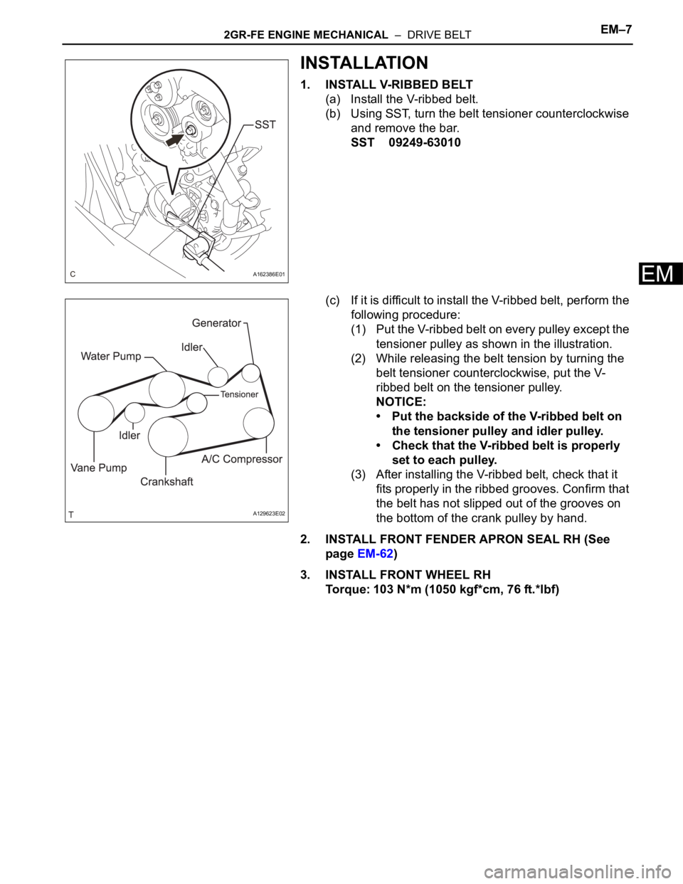
1. INSTALL V-RIBBED BELT
(a) Install the V-ribbed belt.
(b) Using SST, turn the belt tensioner counterclockwise
and remove the bar.
SST 09249-63010
(c) If it is difficult to install the V-ribbed belt, perform the
following procedure:
(1) Put the V-ribbed belt on every pulley except the
tensioner pulley as shown in the illustration.
(2) While releasing the belt tension by turning the
belt tensioner counterclockwise, put the V-
ribbed belt on the tensioner pulley.
NOTICE:
• Put the backside of the V-ribbed belt on
the tensioner pulley and idler pulley.
• Check that the V-ribbed belt is properly
set to each pulley.
(3) After installing the V-ribbed belt, check that it
fits properly in the ribbed grooves. Confirm that
the belt has not slipped out of the grooves on
the bottom of the crank pulley by hand.
2. INSTALL FRONT FENDER APRON SEAL RH (See
page EM-62)
3. INSTALL FRONT WHEEL RH
Torque: 103 N*m (1050 kgf*cm, 76 ft.*lbf)
A162386E01
A129623E02