2007 TOYOTA SIENNA parking brake
[x] Cancel search: parking brakePage 1 of 3000

INTRODUCTION – REPAIR INSTRUCTIONIN–25
IN
VEHICLE LIFT AND SUPPORT
LOCATIONS
1. NOTICE ABOUT VEHICLE CONDITION WHEN
JACKING UP VEHICLE
(a) The vehicle must be unloaded before jacking up/
lifting up the vehicle. Never jack up/lift up a heavily
loaded vehicle.
(b) When removing heavy parts such as the engine and
transmission, the center of gravity of the vehicle
may shift. To stabilize the vehicle, place a balance
weight in a location where it will not roll or shift, or
use a transmission jack to hold the jacking support.
2. NOTICE FOR USING 4 POST LIFT
(a) Follow the safety procedures outlined in the lift
instruction manual.
(b) Use precautionary measures to prevent the free
wheel beam from damaging tires or wheels.
(c) Use wheel chocks to secure the vehicle.
3. NOTICE FOR USING JACK AND SAFETY STAND
(a) Work on a level surface. Use wheel chocks at all
times.
(b) Set the jack and rigid racks to the specified
locations of the vehicle accurately.
(c) When jacking up the vehicle, first release the
parking brake and move the shift lever to N.
(d) When jacking up the entire vehicle:
(1) When jacking up the front wheels first, make
sure wheel chocks are behind the rear wheels.
(2) When jacking up the rear wheels first, make sure
wheel chocks are in front of the front wheels.
(e) When jacking up only the front or rear wheels of the
vehicle:
(1) Before jacking up the front wheels, place wheel
chocks on both sides of the rear wheels.
(2) Before jacking up the rear wheels, place wheel
chocks on both sides of the front wheels.
(f) When lowering a vehicle that only has its front or
rear wheels jacked up:
(1) Before lowering the front wheels, make sure
wheel chocks are in front of the rear wheels.
(2) Before lowering the rear wheels, make sure
wheel chocks are behind the front wheels.
Page 180 of 3000

BC–4BRAKE CONTROL – ANTI-LOCK BRAKE SYSTEM
BC
TEST MODE PROCEDURE
1. SPEED SENSOR SIGNAL CHECK (WHEN USING SST
CHECK WIRE):
HINT:
• If the ignition switch is turned from the ON to the ACC
or LOCK position during Test Mode, the DTCs of the
signal check function will be erased.
(a) Turn the ignition switch off.
(b) Check that the steering wheel is in the straight-
ahead position and move the shift lever to the P
position (Automatic Transmission) or apply the
parking brake (Manual Transmission).
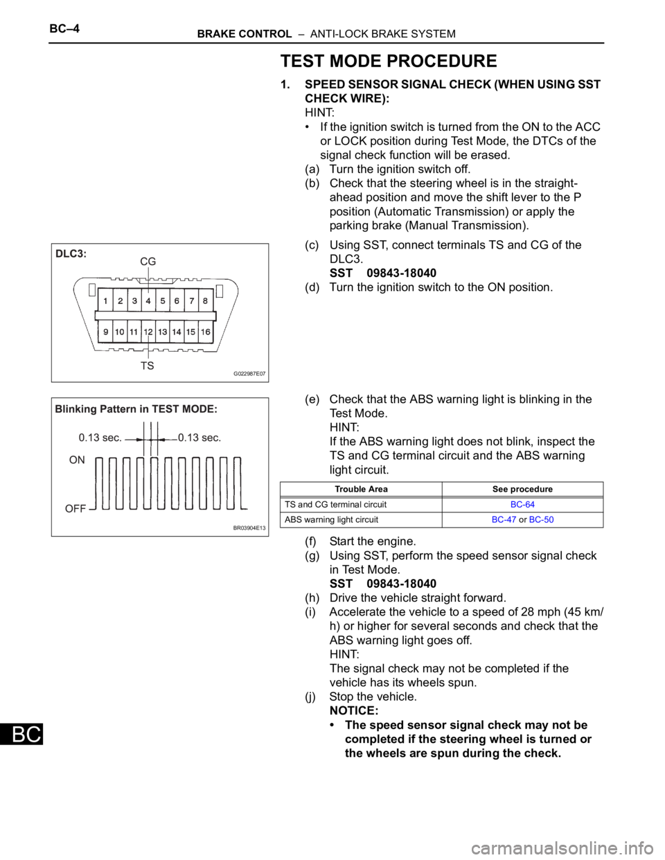
(c) Using SST, connect terminals TS and CG of the
DLC3.
SST 09843-18040
(d) Turn the ignition switch to the ON position.
(e) Check that the ABS warning light is blinking in the
Test Mode.
HINT:
If the ABS warning light does not blink, inspect the
TS and CG terminal circuit and the ABS warning
light circuit.
(f) Start the engine.
(g) Using SST, perform the speed sensor signal check
in Test Mode.
SST 09843-18040
(h) Drive the vehicle straight forward.
(i) Accelerate the vehicle to a speed of 28 mph (45 km/
h) or higher for several seconds and check that the
ABS warning light goes off.
HINT:
The signal check may not be completed if the
vehicle has its wheels spun.
(j) Stop the vehicle.
NOTICE:
• The speed sensor signal check may not be
completed if the steering wheel is turned or
the wheels are spun during the check.
G022987E07
BR03904E13
Trouble Area See procedure
TS and CG terminal circuitBC-64
ABS warning light circuitBC-47 or BC-50
Page 187 of 3000

PARKING BRAKE – PARKING BRAKE PEDALPB–5
PB
REMOVAL
1. DISCONNECT BATTERY NEGATIVE TERMINAL
2. REMOVE FRONT DOOR SCUFF PLATE LH
3. REMOVE COWL SIDE TRIM BOARD LH
4. REMOVE INSTRUMENT PANEL FINISH PANEL SUB-
ASSEMBLY LOWER LH (See page IP-6)
5. REMOVE REAR DOOR SCUFF PLATE RH
6. REMOVE REAR DOOR SCUFF PLATE LH
7. REMOVE FRONT SEAT ASSEMBLY LH
HINT:
• Manual Seat Type (See page SE-48)
• Power Seat Type (See page SE-58)
• Fold Flat Type (See page SE-40)
8. REMOVE REAR SEAT NO.1 ASSEMBLY
HINT:
• Captain Seat Type (See page SE-68)
• Center Seat Type (See page SE-77)
9. REMOVE REAR FLOOR SEAT LOCK COVER
10. REMOVE REAR FLOOR SEAT LOCK COVER
11. REMOVE PARKING BRAKE CONTROL PEDAL
ASSEMBLY
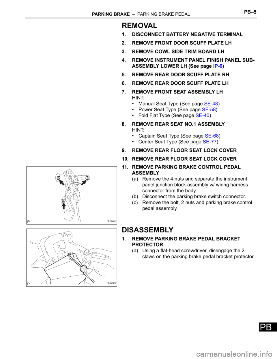
(a) Remove the 4 nuts and separate the instrument
panel junction block assembly w/ wiring harness
connector from the body.
(b) Disconnect the parking brake switch connector.
(c) Remove the bolt, 2 nuts and parking brake control
pedal assembly.
DISASSEMBLY
1. REMOVE PARKING BRAKE PEDAL BRACKET
PROTECTOR
(a) Using a flat-head screwdriver, disengage the 2
claws on the parking brake pedal bracket protector.
F045025
F045029
Page 188 of 3000

PB–6PARKING BRAKE – PARKING BRAKE PEDAL
PB
(b) Turning the parking brake pedal bracket protector
clockwise, remove the parking brake pedal bracket
protector from the parking brake control pedal.
2. REMOVE PARKING BRAKE CABLE ASSEMBLY NO.1
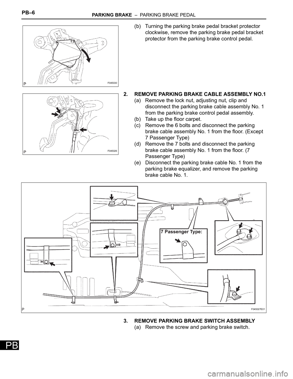
(a) Remove the lock nut, adjusting nut, clip and
disconnect the parking brake cable assembly No. 1
from the parking brake control pedal assembly.
(b) Take up the floor carpet.
(c) Remove the 6 bolts and disconnect the parking
brake cable assembly No. 1 from the floor. (Except
7 Passenger Type)
(d) Remove the 7 bolts and disconnect the parking
brake cable assembly No. 1 from the floor. (7
Passenger Type)
(e) Disconnect the parking brake cable No. 1 from the
parking brake equalizer, and remove the parking
brake cable No. 1.
3. REMOVE PARKING BRAKE SWITCH ASSEMBLY
(a) Remove the screw and parking brake switch.
F045030
F045026
F045027E01
Page 643 of 3000

ES–3502GR-FE ENGINE CONTROL SYSTEM – SFI SYSTEM
ES
(f) Securely apply the parking brake and move the gear
selector lever to the D position (Procedure "A").
(g) While depressing the brake pedal securely, fully depress
the accelerator pedal for 5 seconds (Procedure "B").
(h) Select the following menu items on the tester:
DIAGNOSIS / ENHANCED OBD II / DTC INFO /
CURRENT CODES.
(i) Read the DTCs.
HINT:
The voltage output of the throttle position sensor can be
checked during procedure "B" using the intelligent tester.
Variations in the voltage output indicate that the throttle
actuator is in operation. To check the voltage output
using the intelligent tester, select the following menu
items: DIAGNOSIS / ENHANCED OBD II / DATA LIST /
PRIMARY / THROTTLE POS #1.
OK:
No DTC output.
NG
OKREPLACE THROTTLE BODY (See page ES-
493)
CHECK FOR INTERMITTENT PROBLEMS
Page 1389 of 3000

AX–12U151E AUTOMATIC TRANSAXLE – AUTOMATIC TRANSAXLE SYSTEM
AX
(d) 2 position test:
Shift into the 2 position and fully depress the
accelerator pedal and check the following points.
(1) Check up-shift operation.
Check that the 1
2 up-shift takes place and
that the shift point conforms to the automatic
shift schedule (See page SS-24).
HINT:
There is no 3rd up-shift and lock-up in the 2
position.
(2) Check engine braking.
While running in the 2 position and 2nd gear,
release the accelerator pedal and check the
engine braking effect.
(3) Check for abnormal noise during acceleration
and deceleration, and for shock at up-shift and
down-shift.
(e) L position test:
Shift into the L position and fully depress the
accelerator pedal and check the following points.
(1) Check no up-shift.
While running in the L position, check that there
is no up-shift to 2nd gear.
HINT:
There is no lock-up in the L position.
(2) Check engine braking.
While running in the L position, release the
accelerator pedal and check the engine braking
effect.
(3) Check for abnormal noise during acceleration
and deceleration.
(f) R position test:
Shift into the R position and fully depress the
accelerator pedal and check for slipping.
CAUTION:
Before conducting this test ensure that the test
area is free from people and obstruction.
(g) P position test:
Stop the vehicle on the grade (more than 5
) and
after shifting into the P position, release the parking
brake. Then, check that the parking lock pawl holds
the vehicle in place.
(h) Uphill/downhill control function test:
(1) Check that the gear does not up-shift to the 4th
or 5th gear while the vehicle is driving uphill.
(2) Check that the gear automatically down-shifts
from 5th to 4th or from the 4th to 3rd gear when
brake is applied while the vehicle is driving
downhill.
Page 1390 of 3000

U151E AUTOMATIC TRANSAXLE – AUTOMATIC TRANSAXLE SYSTEMAX–13
AX
MECHANICAL SYSTEM TESTS
1. PERFORM MECHANICAL SYSTEM TESTS
(a) Measure the stall speed.
The object of this test is to check the overall
performance of the transaxle and engine by
measuring the stall speeds in the D position.
NOTICE:
• Driving test should be done on a paved road
(a nonskid road).
• Perform the test at the normal operating ATF
(Automatic Transmission Fluid) temperature
50 to 80
C (122 to 176F).
• Do not continuously run this test for longer
than 10 seconds.
• To ensure safety, do this test in a wide, clear
level area which provides good traction.
• The stall test should always be carried out in
pairs. One technician should observe the
conditions of wheels or wheel stoppers
outside the vehicle while the other is doing
the test.
(1) Chock the 4 wheels.
(2) Connect the intelligent tester together with the
CAN VIM (controller area network vehicle
interface module) to the DLC3.
(3) Fully apply the parking brake.
(4) Keep your left foot pressed firmly on the brake
pedal.
(5) Start the engine.
(6) Shift into the D position. Press all the way down
on the accelerator pedal with your right foot.
(7) Quickly read the stall speed at this time.
Stall speed:
2,300 +- 150 rpm
Evaluation:
Problem Possible cause
(a) Stall engine speed is low in D position• Engine power output may be insufficient
• Stator one-way clutch not operating properly
HINT:
If the value is less than the specified value by 600 rpm or more, the
torque converter could be faulty.
(b) Stall engine speed is high in D position• Line pressure is too low
• Forward clutch slipping
• U/D (Underdrive) brake slipping
• U/D (Underdrive) one-way clutch is not operating properly
• No.1 one-way clutch not operating properly
• Improper fluid level
Page 1391 of 3000

AX–14U151E AUTOMATIC TRANSAXLE – AUTOMATIC TRANSAXLE SYSTEM
AX
(b) Measure the time lag.
(1) When the shift lever is shifted while the engine is
idling, there will be a certain time lapse or lag
before the shock can be felt. This is used for
checking the condition of the clutch and brake.
NOTICE:
• Perform the test at the normal operating
ATF (Automatic Transmission Fluid)
temperature: 50 to 80
C (122 to 176F).
• Be sure to allow 1 minute interval between
tests.
• Perform the test three times, and measure
the time lags. Calculate the average value
of the three time lags.
• When conducting stall test, do not
continue more than 10 seconds.
(2) Connect the intelligent tester together with the
CAN VIM (controller area network vehicle
interface module) to the DLC3.
(3) Fully apply the parking brake.
(4) Start and warm up the engine and check idle
speed.
Idle speed:
approx. 700 rpm (In N position and A/C
OFF)
(5) Shift the lever from N to D position. Using a stop
watch, measure the time from when the lever is
shifted until the shock is felt.
Time lag:
N
D less than 1.2 seconds
(6) In the same way, measure the time lag for N
R.
Time lag:
N
R less than 1.5 seconds
Evaluation (If N
D or N R time lag is longer than the specified):
Problem Possible cause
N
D time lag is longer• Line pressure is too low
• Forward clutch worn
• No.1 one-way clutch is not operating properly
• U/D (Underdrive) one-way clutch is not operating
• U/D (Underdrive) brake worn
N
R time lag is longer• Line pressure is too low
• Reverse clutch worn
• 1st and reverse brake worn
• U/D (Underdrive) brake worn