Page 2575 of 3000
BC–194BRAKE CONTROL – REAR SPEED SENSOR (for 4WD)
BC
REMOVAL
HINT:
Remove the RH side by the same procedure as the LH side.
1. REMOVE REAR WHEEL
2. REMOVE QUARTER TRIM PANEL ASSEMBLY
FRONT LH
HINT:
Remove the LH side by the same procedure as the RH
side (See page IR-9).
3. REMOVE REAR SPEED SENSOR
(a) Disconnect the speed sensor connector, and pull
out the sensor wire harness with grommet.
(b) Remove the clamp bolt holding the sensor harness
from the body.
(c) Remove the bolt and speed sensor rear LH.
NOTICE:
Keep the tip of the speed sensor rear LH clean.
F040305
G024305
G023898
Page 2593 of 3000

BR–20BRAKE – BRAKE BOOSTER
BR
REMOVAL
NOTICE:
• Do not adjust the brake booster push rod.
• Do not change the combination of the diameter
converting unit and brake.
1. REMOVE FRONT WHEEL
2. DRAIN BRAKE FLUID
NOTICE:
Wash the brake fluid off immediately if it attaches to
any painted surfaces.
3. SEPARATE BATTERY NEGATIVE TERMINAL
4. REMOVE FRONT DOOR SCUFF PLATE LH
5. REMOVE COWL SIDE TRIM BOARD LH
(a) Remove the nut and cowl trim board plate LH.
6. REMOVE INSTRUMENT PANEL FINISH PANEL SUB-
ASSEMBLY LOWER LH
(a) Remove the 2 bolts and instrument panel finish
panel sub-assembly lower LH.
7. REMOVE INSTRUMENT PANEL SAFETY PAD
INSERT SUB-ASSEMBLY NO. 1
(a) Remove the 4 bolts and instrument panel safety pad
insert sub-assembly No. 1.
8. REMOVE COWL TOP PANEL SUB-ASSEMBLY
OUTER FRONT (See page SP-13)
9. REMOVE AIR CLEANER ASSEMBLY WITH HOSE
10. REMOVE BRAKE ACTUATOR ASSEMBLY (w/o VSC)
SST 09023-00101
HINT:
See page BC-184.
11. REMOVE ABS & TRACTION ACTUATOR ASSEMBLY
(w/ VSC)
SST 09023-00101
HINT:
See page BC-179.
12. REMOVE BRAKE LINE
(a) Remove the front brake tube No. 1, front brake tube
No. 2, front brake tube No. 3 and front brake tube
No. 4.
(b) Remove the rear brake tube No. 1 and rear brake
tube No. 2.
13. REMOVE PUSH ROD PIN
(a) Remove the push rod pin from the brake booster
push rod.
14. REMOVE BRAKE MASTER CYLINDER ASSEMBLY
(a) Slide the clip and disconnect the brake master
cylinder reservoir hose from the brake master
cylinder union.
Page 2597 of 3000

BRAKE – BRAKE FLUIDBR–5
BR
(d) Perform air bleeding according to "Step 1: Increase"
on the intelligent tester display.
NOTICE:
Make sure that the master cylinder reservoir
tank does not become empty of brake fluid.
(1) Connect a vinyl tube to either one of the
bleeder plugs.
(2) Depress the brake pedal several times, then
loosen the bleeder plug connected to the vinyl
tube with the pedal depressed (*7).
(3) When fluid stops coming out, tighten the
bleeder plug, then release the brake pedal (*8).
(4) Repeat (*7) and (*8) until all the air in the fluid
is completely bled out.
(5) Tighten the bleeder plug completely.
To r q u e : D i s c
8.3 N*m (85 kgf*cm, 73 in.*lbf)
Drum
11 N*m (112 kgf*cm, 8 ft.*lbf)
(6) Repeat the above procedures for the rest of the
wheels to bleed the air from the brake line.
(e) Bleed the air from the suction line according to "Step
2: Inhalation" on the intelligent tester display.
NOTICE:
• Bleed the suction line by following the steps
displayed on the intelligent tester.
• Make sure that the master cylinder reservoir
tank does not become empty of brake fluid.
(1) Connect a vinyl tube to the bleeder plug at the
right front wheel or the right rear wheel and
loosen the bleeder plug.
(2) Operate the brake actuator assembly to
perform air bleeding using the intelligent tester
(*9).
NOTICE:
• The operation stops automatically in 4
seconds.
• At this time, be sure to release the brake
pedal.
(3) Check that the operation has stopped by
referring to the intelligent tester display and
tighten the bleeder plug (*10).
(4) Repeat (*9) and (*10) until all the air in the fluid
is completely bled out.
(5) Tighten the bleeder plug completely.
To r q u e : D i s c
8.3 N*m (85 kgf*cm, 73 in.*lbf)
Drum
11 N*m (112 kgf*cm, 8 ft.*lbf)
(6) For the rest of the wheels, perform air bleeding
in the same way as stated in the above
procedure.
Page 2628 of 3000

BRAKE – REAR DISC BRAKEBR–31
BR
REMOVAL
HINT:
Remove the RH side by the same procedure as the LH side.
1. REMOVE REAR WHEEL
2. DRAIN BRAKE FLUID
NOTICE:
Wash the brake fluid off immediately if it attaches to
any painted surface.
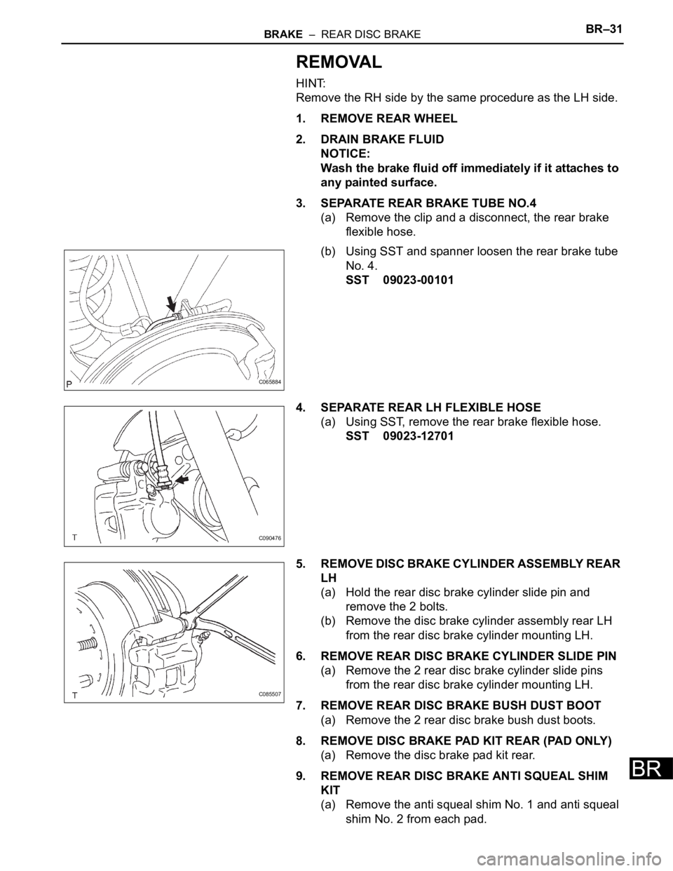
3. SEPARATE REAR BRAKE TUBE NO.4
(a) Remove the clip and a disconnect, the rear brake
flexible hose.
(b) Using SST and spanner loosen the rear brake tube
No. 4.
SST 09023-00101
4. SEPARATE REAR LH FLEXIBLE HOSE
(a) Using SST, remove the rear brake flexible hose.
SST 09023-12701
5. REMOVE DISC BRAKE CYLINDER ASSEMBLY REAR
LH
(a) Hold the rear disc brake cylinder slide pin and
remove the 2 bolts.
(b) Remove the disc brake cylinder assembly rear LH
from the rear disc brake cylinder mounting LH.
6. REMOVE REAR DISC BRAKE CYLINDER SLIDE PIN
(a) Remove the 2 rear disc brake cylinder slide pins
from the rear disc brake cylinder mounting LH.
7. REMOVE REAR DISC BRAKE BUSH DUST BOOT
(a) Remove the 2 rear disc brake bush dust boots.
8. REMOVE DISC BRAKE PAD KIT REAR (PAD ONLY)
(a) Remove the disc brake pad kit rear.
9. REMOVE REAR DISC BRAKE ANTI SQUEAL SHIM
KIT
(a) Remove the anti squeal shim No. 1 and anti squeal
shim No. 2 from each pad.
C065884
C090476
C085507
Page 2633 of 3000
BR–36BRAKE – REAR DISC BRAKE
BR
(b) Using SST and a spanner, connect the rear brake
tube No. 4.
SST 09023-00101
Torque: 15 N*m (155 kgf*cm, 11 ft.*lbf)
8. FILL RESERVOIR WITH BRAKE FLUID (See page BR-
3)
9. BLEED BRAKE MASTER CYLINDER (See page BR-3)
10. BLEED BRAKE LINE (See page BR-4)
11. BLEED BRAKE ACTUATOR (w/ VSC) (See page BR-
4)
12. CHECK FLUID LEVEL IN RESERVOIR (See page BR-
7)
13. CHECK BRAKE FLUID LEAKAGE
14. INSTALL REAR WHEEL
Torque: 103 N*m (1,050 kgf*cm, 76 ft.*lbf)
C065884
Page 2635 of 3000
BR–36BRAKE – REAR DISC BRAKE
BR
(b) Using SST and a spanner, connect the rear brake
tube No. 4.
SST 09023-00101
Torque: 15 N*m (155 kgf*cm, 11 ft.*lbf)
8. FILL RESERVOIR WITH BRAKE FLUID (See page BR-
3)
9. BLEED BRAKE MASTER CYLINDER (See page BR-3)
10. BLEED BRAKE LINE (See page BR-4)
11. BLEED BRAKE ACTUATOR (w/ VSC) (See page BR-
4)
12. CHECK FLUID LEVEL IN RESERVOIR (See page BR-
7)
13. CHECK BRAKE FLUID LEAKAGE
14. INSTALL REAR WHEEL
Torque: 103 N*m (1,050 kgf*cm, 76 ft.*lbf)
C065884
Page 2637 of 3000
BRAKE – REAR DRUM BRAKEBR–37
BR
DISASSEMBLY
1. REMOVE REAR WHEEL
2. DRAIN BRAKE FLUID
NOTICE:
Wash the brake fluid off immediately if it attaches to
any painted surface.
3. REMOVE REAR BRAKE DRUM SUB-ASSEMBLY
(a) Release the parking brake lever, and remove the
rear brake drum.
HINT:
If the rear brake drum cannot be removed easily,
perform the following procedure.
(b) Remove the hole plug and insert a screwdriver
through the hole in the backing plate, and hold the
automatic adjusting lever away from the adjuster.
(c) Using another screwdriver, reduce the brake shoe
adjuster by turning the adjusting wheel.
4. REMOVE FRONT BRAKE SHOE
(a) Using SST, remove the shoe return spring from the
front brake shoe.
SST 09921-00010
(b) Using a needle-nose pliers, remove the return
spring.
F040009
C094667E01
C094668
Page 2638 of 3000

BR–38BRAKE – REAR DRUM BRAKE
BR
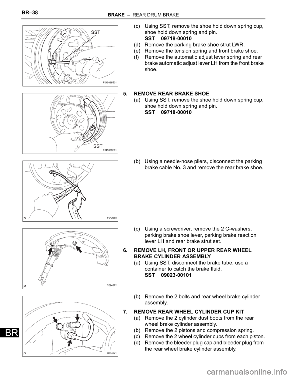
(c) Using SST, remove the shoe hold down spring cup,
shoe hold down spring and pin.
SST 09718-00010
(d) Remove the parking brake shoe strut LWR.
(e) Remove the tension spring and front brake shoe.
(f) Remove the automatic adjust lever spring and rear
brake automatic adjust lever LH from the front brake
shoe.
5. REMOVE REAR BRAKE SHOE
(a) Using SST, remove the shoe hold down spring cup,
shoe hold down spring and pin.
SST 09718-00010
(b) Using a needle-nose pliers, disconnect the parking
brake cable No. 3 and remove the rear brake shoe.
(c) Using a screwdriver, remove the 2 C-washers,
parking brake shoe lever, parking brake reaction
lever LH and rear brake strut set.
6. REMOVE LH, FRONT OR UPPER REAR WHEEL
BRAKE CYLINDER ASSEMBLY
(a) Using SST, disconnect the brake tube, use a
container to catch the brake fluid.
SST 09023-00101
(b) Remove the 2 bolts and rear wheel brake cylinder
assembly.
7. REMOVE REAR WHEEL CYLINDER CUP KIT
(a) Remove the 2 cylinder dust boots from the rear
wheel brake cylinder assembly.
(b) Remove the 2 pistons and compression spring.
(c) Remove the 2 wheel cylinder cups from each piston.
(d) Remove the bleeder plug cap and bleeder plug from
the rear wheel brake cylinder assembly.
F045068E01
F045069E01
F042688
C094672
C094671