Page 236 of 3000

THEFT DETERRENT – THEFT DETERRENT SYSTEMTD–3
TD
SYSTEM DESCRIPTION
1. OUTLINE OF THEFT DETERRENT SYSTEM
(a) When the theft deterrent system detects that the
vehicle is being tampered with, the system sets off
the alarm, causing the horns to sound and the lights
to light up or blink in order to alert people around the
vehicle to the theft.
(b) The theft deterrent system has 2 modes; one is the
active arming mode (see ACTIVE ARMING MODE)
and the other is passive arming mode (see
PASSIVE ARMING MODE). The passive arming
mode can be switched ON/OFF using the specified
method.
(c) Each mode has 4 states; a disarmed state, an
arming preparation state, an armed state and an
alarm sounding state.
(1) Disarmed state:
• The alarm function is not operating.
• The theft deterrent system is not operating.
(2) Arming preparation state:
• The time until the system goes into the armed
state.
• The theft deterrent system is not operating.
(3) Armed state:
• The theft deterrent system is operating.
(4) Alarm sounding state:
• Alarm function is operating.
Alarm time:
Approx. 60 sec.
Refer to table below for alarm method and time:
HINT:
If any of the doors are unlocked with no key in
the ignition key cylinder during the armed state,
a forced door lock signal will be output (see
FORCED DOOR LOCK CONTROL).
2. ACTIVE ARMING MODE
HINT:
• Active arming mode starts the alarm control
immediately after the doors are locked.
• This system activates as described in the diagram
below when one of items for each condition is met.
Alarm MethodHeadlight Blinking (approx. 0.4 second cycles)
Taillight Blinking (approx. 0.4 second cycles)
Hazard Warning Light Blinking (cycles of flasher relay)
Interior Light Illuminating
Vehicle HornSounding
(approx. 0.4 second cycles)
Security HornSounding
(approx. 0.4 second cycles)
Alarm Time Approx. 60 sec.
Page 289 of 3000
INSTRUMENT PANEL – INSTRUMENT PANEL SAFETY PADIP–5
IP
REMOVAL
1. BOLT, SCREW AND NUT TABLE
(a) The bolts, the screws and the nuts, which are
necessary for installation and removal of the
instrument panel are shown in the illustration below
with alphabets.
2. DISCONNECT BATTERY NEGATIVE TERMINAL (See
page RS-423)
3. REMOVE STEERING WHEEL COVER LOWER NO.2
4. REMOVE STEERING WHEEL COVER LOWER NO.3
5. REMOVE HORN BUTTON ASSEMBLY (See page RS-
424)
6. REMOVE STEERING WHEEL ASSEMBLY (See page
SR-6)
7. REMOVE STEERING COLUMN COVER (See page
RS-434)
8. REMOVE HEADLIGHT DIMMER SWITCH ASSEMBLY
(See page LI-102)
9. REMOVE WINDSHIELD WIPER SWITCH ASSEMBLY
(See page WW-17)
B066709E01
Page 1246 of 3000
2GR-FE COOLING – RADIATORCO–31
CO
(b) Detach the clamp.
(c) Disconnect the low pitched horn and high pitched
horn connectors.
(d) Remove the 2 bolts and hood lock support sub-
assembly.
15. DISCONNECT COOLING FAN ECU CONNECTOR
(a) Disconnect the cooling fan ECU connector.
(b) Detach the clamp.
16. REMOVE RADIATOR UPPER SUPPORT SUB-
ASSEMBLY
(a) Remove the 4 bolts and radiator upper support sub-
assembly.
A161458E01
A161460
A161472E01
A161463
Page 1262 of 3000
CO–442GR-FE COOLING – RADIATOR
CO
15. INSTALL HOOD LOCK SUPPORT SUB-ASSEMBLY
(a) Install the hood lock support sub-assembly with the
2 bolts.
(b) Attach the clamp.
(c) Connect the low pitched horn and high pitched horn
connectors.
(d) Connect the ambient temperature sensor connector.
16. INSTALL HOOD LOCK ASSEMBLY
(a) Connect the cable to the hood lock assembly.
(b) Install the hood lock assembly with the 3 bolts.
Torque: 8 N*m (82 kgf*cm, 6 ft.*lbf)
(c) With Hood Courtesy Switch:
(1) Connect the connector.
A161460
A161458
A161459
A162807
A161457
Page 1276 of 3000
2GR-FE COOLING – RADIATORCO–31
CO
(b) Detach the clamp.
(c) Disconnect the low pitched horn and high pitched
horn connectors.
(d) Remove the 2 bolts and hood lock support sub-
assembly.
15. DISCONNECT COOLING FAN ECU CONNECTOR
(a) Disconnect the cooling fan ECU connector.
(b) Detach the clamp.
16. REMOVE RADIATOR UPPER SUPPORT SUB-
ASSEMBLY
(a) Remove the 4 bolts and radiator upper support sub-
assembly.
A161458E01
A161460
A161472E01
A161463
Page 1289 of 3000
CO–442GR-FE COOLING – RADIATOR
CO
15. INSTALL HOOD LOCK SUPPORT SUB-ASSEMBLY
(a) Install the hood lock support sub-assembly with the
2 bolts.
(b) Attach the clamp.
(c) Connect the low pitched horn and high pitched horn
connectors.
(d) Connect the ambient temperature sensor connector.
16. INSTALL HOOD LOCK ASSEMBLY
(a) Connect the cable to the hood lock assembly.
(b) Install the hood lock assembly with the 3 bolts.
Torque: 8 N*m (82 kgf*cm, 6 ft.*lbf)
(c) With Hood Courtesy Switch:
(1) Connect the connector.
A161460
A161458
A161459
A162807
A161457
Page 2587 of 3000

BRAKE CONTROL – STEERING ANGLE SENSORBC–199
BC
REMOVAL
1. PRECAUTION
HINT:
See page RS-1
2. SEPARATE BATTERY NEGATIVE TERMINAL
3. PLACE FRONT WHEELS FACING STRAIGHT AHEAD
4. REMOVE HORN BUTTON ASSEMBLY (See page RS-
424)
5. REMOVE STEERING WHEEL ASSEMBLY (See page
SR-6)
6. REMOVE STEERING COLUMN COVER LWR (See
page RS-434)
7. REMOVE SPIRAL CABLE SUB-ASSEMBLY (See page
RS-434)
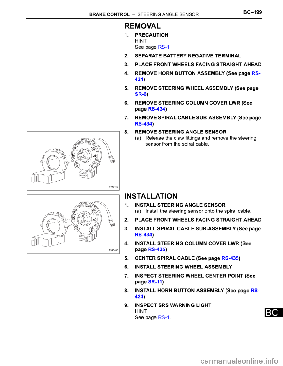
8. REMOVE STEERING ANGLE SENSOR
(a) Release the claw fittings and remove the steering
sensor from the spiral cable.
INSTALLATION
1. INSTALL STEERING ANGLE SENSOR
(a) Install the steering sensor onto the spiral cable.
2. PLACE FRONT WHEELS FACING STRAIGHT AHEAD
3. INSTALL SPIRAL CABLE SUB-ASSEMBLY (See page
RS-434)
4. INSTALL STEERING COLUMN COVER LWR (See
page RS-435)
5. CENTER SPIRAL CABLE (See page RS-435)
6. INSTALL STEERING WHEEL ASSEMBLY
7. INSPECT STEERING WHEEL CENTER POINT (See
page SR-11)
8. INSTALL HORN BUTTON ASSEMBLY (See page RS-
424)
9. INSPECT SRS WARNING LIGHT
HINT:
See page RS-1.
F045466
F045466
Page 2670 of 3000

SR–6STEERING COLUMN – STEERING COLUMN ASSEMBLY
SR
REMOVAL
1. PRECAUTION
HINT:
See page RS-1
2. DISCONNECT BATTERY NEGATIVE TERMINAL
Wait for 90 seconds after disconnecting the battery
terminal to prevent the airbag working.
3. PLACE FRONT WHEELS FACING STRAIGHT AHEAD
4. REMOVE STEERING WHEEL COVER LOWER NO.2
(See page RS-424)
5. REMOVE STEERING WHEEL COVER LOWER NO.3
(See page RS-424)
6. REMOVE HORN BUTTON ASSEMBLY (See page RS-
424)
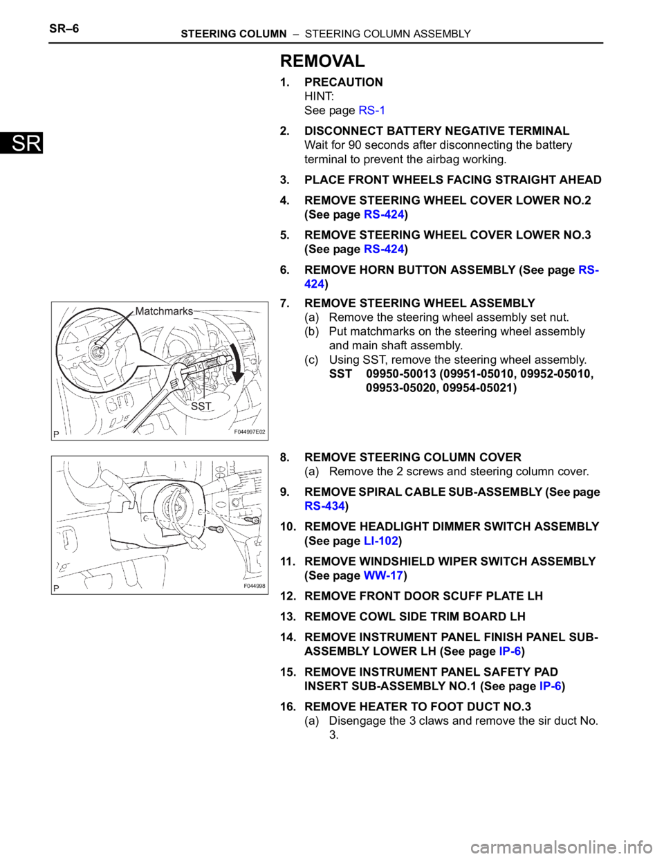
7. REMOVE STEERING WHEEL ASSEMBLY
(a) Remove the steering wheel assembly set nut.
(b) Put matchmarks on the steering wheel assembly
and main shaft assembly.
(c) Using SST, remove the steering wheel assembly.
SST 09950-50013 (09951-05010, 09952-05010,
09953-05020, 09954-05021)
8. REMOVE STEERING COLUMN COVER
(a) Remove the 2 screws and steering column cover.
9. REMOVE SPIRAL CABLE SUB-ASSEMBLY (See page
RS-434)
10. REMOVE HEADLIGHT DIMMER SWITCH ASSEMBLY
(See page LI-102)
11. REMOVE WINDSHIELD WIPER SWITCH ASSEMBLY
(See page WW-17)
12. REMOVE FRONT DOOR SCUFF PLATE LH
13. REMOVE COWL SIDE TRIM BOARD LH
14. REMOVE INSTRUMENT PANEL FINISH PANEL SUB-
ASSEMBLY LOWER LH (See page IP-6)
15. REMOVE INSTRUMENT PANEL SAFETY PAD
INSERT SUB-ASSEMBLY NO.1 (See page IP-6)
16. REMOVE HEATER TO FOOT DUCT NO.3
(a) Disengage the 3 claws and remove the sir duct No.
3.
F044997E02
F044998