2007 TOYOTA SIENNA Oxygen sensors
[x] Cancel search: Oxygen sensorsPage 326 of 3000

ES–2582GR-FE ENGINE CONTROL SYSTEM – SFI SYSTEM
ES
MONITOR DESCRIPTION
The ECM uses the sensors mounted in front of and behind the three-way catalyst (TWC) to monitor its
efficiency. The first sensor, an Air Fuel ratio (A/F) sensor, sends pre-catalyst A/F ratio information to the
ECM. The second sensor, a heated oxygen sensor (O2S), sends post-catalyst information to the ECM.
The ECM compares these 2 signals to judge the efficiency of the catalyst and the catalyst's ability to store
oxygen. During normal operation, the TWC stores and releases oxygen as needed. The capacity to store
oxygen results in a low variation in the post-TWC exhaust stream.
If the catalyst is functioning normally, the waveform of the heated oxygen sensor slowly switches between
RICH and LEAN. If the catalyst is deteriorated, the waveform will alternate frequently between RICH and
LEAN. As the catalyst efficiency degrades, its ability to store oxygen is reduced and the catalyst output
becomes more variable. When running the monitor, the ECM compares sensor 1 signals (A/F sensor)
over a specific amount of time to determine catalyst efficiency. The ECM begins by calculating the signal
length for both sensors (for the rear oxygen sensor, the ECM uses the output voltage signal length). If the
oxygen sensor output voltage signal length is greater than the threshold (threshold is calculated based on
the A/F sensor signal length), the ECM concludes that the catalyst is malfunctioning. The ECM will turn on
the MIL and a DTC will be set.
HINT:
• Bank 1 refers to the bank that includes cylinder No. 1.
• Bank 2 refers to the bank that does not include cylinder No. 1.
• Sensor 1 refers to the sensor closest to the engine assembly.
• Sensor 2 refers to the sensor farthest away from the engine assembly.
MONITOR STRATEGY
DTC P0420Catalyst System Efficiency Below Threshold
(Bank 1)
DTC P0430Catalyst System Efficiency Below Threshold
(Bank 2)
DTC No. DTC Detection Condition Trouble Area
P0420Oxygen Storage Capacity (OSC) value is smaller than
standard value under active air-fuel ratio control (2 trip
detection logic)• Gas leakage from exhaust system
• A/F sensor (bank 1 sensor 1)
• HO2 sensor (bank 1 sensor 2)
• Exhaust manifold (TWC)
P0430OSC value is smaller than standard value under active
air-fuel ratio control (2 trip detection logic)• Gas leakage from exhaust system
• A/F sensor (bank 2 sensor 1)
• HO2 sensor (bank 2 sensor 2)
• Exhaust manifold (TWC)
Related DTCsP0420: Catalyst Deterioration
P0430: Catalyst Deterioration
Required Sensors / Components (Main) TWC
Required Sensors / Components (Related)A/F sensor, heated oxygen sensor, intake air temperature sensor, mass air flow
meter, crankshaft position sensor and engine coolant temperature sensor
Frequency of Operation Once per driving cycle
Duration Approximately 30 seconds
MIL Operation 2 driving cycles
Sequence of Operation None
Page 327 of 3000

2GR-FE ENGINE CONTROL SYSTEM – SFI SYSTEMES–259
ES
TYPICAL ENABLING CONDITIONS
TYPICAL MALFUNCTION THRESHOLDS
MONITOR RESULT
Refer to CHECKING MONITOR STATUS (See page ES-19).
CONDITIONING FOR SENSOR TESTING
HINT:
Perform the operation with the engine speeds and durations described below prior to checking the
waveforms of the A/F and HO2 sensors. This is in order to activate the sensors sufficiently to obtain the
appropriate inspection results.
The monitor will run whenever these DTCs are not
presentP0011, P0012 (VVT System 1-Advance, Retard), P0021, P0022 (VVT System 2-
Adavance, Retard), P0031, P0032, P0051, P0052 (A/F Sensor Heater Sensor 1),
P0037, P0038, P0057, P0058 (O2 Sensor heater Sensor 2), P0100, P0101, P0102,
P0103 (MAF Sensor), P0115, P0116, P0117, P0118 (ECT Sensor), P0120, P0121,
P0122, P0123, P0220, P0222, P0223 , P2135 (TP Sensor), P0125 (Insufficient ECT
for Closed Loop), P0136, P0156 (O2 Sensor 2), P0171,P0172 (Fuel System),
P0300, P0301, P0302, P0303, P0304, P0305, P0306 (Misfire), P0335 (CKP
Sensor), P0340 (CMP Sensor), P0351, P0352, P0353, P0354, P0355, P0356
(Ignitor), P0500 (VSS), P2196, P2198 (A/F Sensor (Rationality)), P2A00, P2A03 (A/
F Sensor (Slow Response))
Battery voltage 11 V or more
IAT -10
C (14F) or more
ECT 75
C (167F) or more
Atmospheric pressure 0.75 or more
Idle OFF
Engine RPM Less than 3200 rpm
A/F sensor Activated
Fuel system status Closed loop
Engine load 10 to 70%
All of the following conditions are met Conditions 1, 2 and 3
1. Mass air flow rate 5 to 60 g/sec.
2. Front catalyst temperature (estimated) 600 to 750
C (1112 to 1382F)
3. Rear catalyst temperature (estimated) 100 to 900
C (212 to 1652F)
Rear HO2S monitor Completed
Shift position 4th or more
Oxygen Storage Capacity (OSC) of catalyst Less than 0.046 g (0.000101 lb)
Page 328 of 3000
ES–2602GR-FE ENGINE CONTROL SYSTEM – SFI SYSTEM
ES
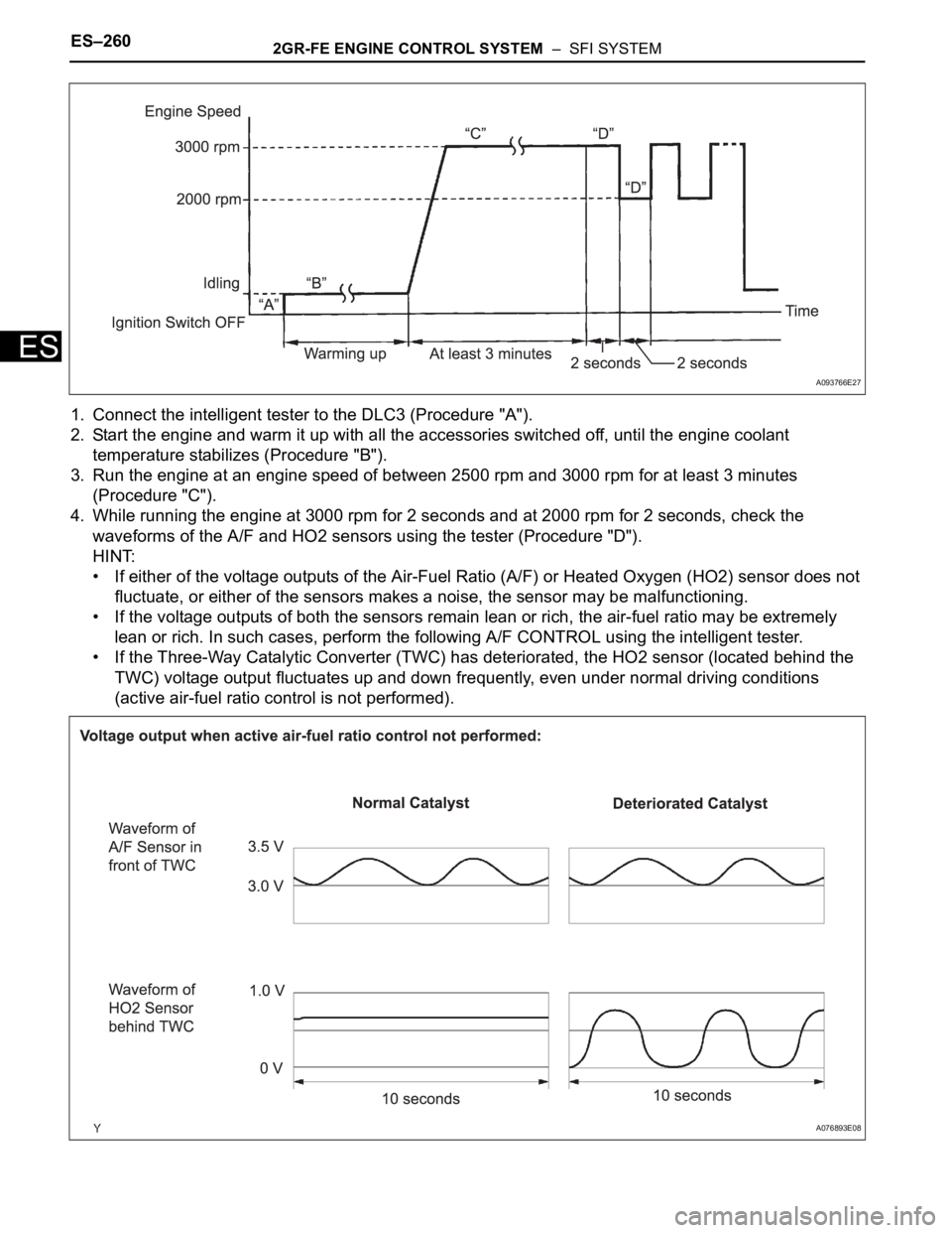
1. Connect the intelligent tester to the DLC3 (Procedure "A").
2. Start the engine and warm it up with all the accessories switched off, until the engine coolant
temperature stabilizes (Procedure "B").
3. Run the engine at an engine speed of between 2500 rpm and 3000 rpm for at least 3 minutes
(Procedure "C").
4. While running the engine at 3000 rpm for 2 seconds and at 2000 rpm for 2 seconds, check the
waveforms of the A/F and HO2 sensors using the tester (Procedure "D").
HINT:
• If either of the voltage outputs of the Air-Fuel Ratio (A/F) or Heated Oxygen (HO2) sensor does not
fluctuate, or either of the sensors makes a noise, the sensor may be malfunctioning.
• If the voltage outputs of both the sensors remain lean or rich, the air-fuel ratio may be extremely
lean or rich. In such cases, perform the following A/F CONTROL using the intelligent tester.
• If the Three-Way Catalytic Converter (TWC) has deteriorated, the HO2 sensor (located behind the
TWC) voltage output fluctuates up and down frequently, even under normal driving conditions
(active air-fuel ratio control is not performed).
A093766E27
A076893E08
Page 329 of 3000
2GR-FE ENGINE CONTROL SYSTEM – SFI SYSTEMES–261
ES
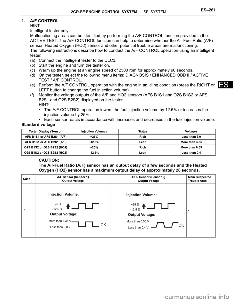
1. A/F CONTROL
HINT:
Intelligent tester only:
Malfunctioning areas can be identified by performing the A/F CONTROL function provided in the
ACTIVE TEST. The A/F CONTROL function can help to determine whether the Air-Fuel Ratio (A/F)
sensor, Heated Oxygen (HO2) sensor and other potential trouble areas are malfunctioning.
The following instructions describe how to conduct the A/F CONTROL operation using an intelligent
tester.
(a) Connect the intelligent tester to the DLC3.
(b) Start the engine and turn the tester on.
(c) Warm up the engine at an engine speed of 2500 rpm for approximately 90 seconds.
(d) On the tester, select the following menu items: DIAGNOSIS / ENHANCED OBD II / ACTIVE
TEST / A/F CONTROL.
(e) Perform the A/F CONTROL operation with the engine in an idling condition (press the RIGHT or
LEFT button to change the fuel injection volume).
(f) Monitor the voltage outputs of the A/F and HO2 sensors (AFS B1S1 and O2S B1S2 or AFS
B2S1 and O2S B2S2) displayed on the tester.
HINT:
• The A/F CONTROL operation lowers the fuel injection volume by 12.5% or increases the
injection volume by 25%.
• Each sensor reacts in accordance with increases and decreases in the fuel injection volume.
Standard voltage
CAUTION:
The Air-Fuel Ratio (A/F) sensor has an output delay of a few seconds and the Heated
Oxygen (HO2) sensor has a maximum output delay of approximately 20 seconds.
Tester Display (Sensor) Injection Volumes Status Voltages
AFS B1S1 or AFS B2S1 (A/F) +25% Rich Less than 3.0
AFS B1S1 or AFS B2S1 (A/F) -12.5% Lean More than 3.35
O2S B1S2 or O2S B2S2 (HO2) +25% Rich More than 0.55
O2S B1S2 or O2S B2S2 (HO2) -12.5% Lean Less than 0.4
CaseA/F Sensor (Sensor 1)
Output VoltageHO2 Sensor (Sensor 2)
Output VoltageMain Suspected
Trouble Area
1-
Page 416 of 3000

ES–1102GR-FE ENGINE CONTROL SYSTEM – SFI SYSTEM
ES
HINT:
• Bank 1 refers to the bank that includes cylinder No. 1.
• Bank 2 refers to the bank that does not include cylinder No. 1.
• Sensor 1 refers to the closest sensor to the engine assembly.
• Sensor 2 refers to the furthest sensor away from the engine assembly.
MONITOR DESCRIPTION
The ECM uses information from the Air-Fuel Ratio (A/F) sensor to regulate the air-fuel ratio and keep it
close to the stoichiometric level. This maximizes the ability of the Three-Way Catalytic Converter (TWC) to
purify the exhaust gas.
The A/F sensor detects oxygen levels in the exhaust gas and transmits the information to the ECM. The
inner surface of the sensor element is exposed to the outside air. The outer surface of the sensor element
is exposed to the exhaust gas. The sensor element is made of platinum coated zirconia and includes an
integrated heating element.
The zirconia element generates small voltage when there is a large difference in the oxygen
concentrations between the exhaust gas and outside air. The platinum coating amplifies this voltage
generation.
The A/F sensor is more efficient when heated. When the exhaust gas temperature is low, the sensor
cannot generate useful voltage signals without supplementary heating. The ECM regulates the
supplementary heating using a duty-cycle approach to adjust the average current in the sensor heater
element. If the heater current is outside the normal range, the signal transmitted by the A/F sensor will be
inaccurate, as a result, the ECM will be unable to regulate air-fuel ratio properly.
When the current in the A/F sensor heater is outside the normal operating range, the ECM interprets this
as a malfunction in the sensor heater and sets a DTC.
Example:
The ECM sets DTC P0032 or P0052 when the current in the A/F sensor heater is more than 10 A.
Conversely, when the heater current is less than 0.8 A, DTC P0031 or P0051 is set.
MONITOR STRATEGY
TYPICAL ENABLING CONDITIONS
All:
P0031 and P0051:
P0032
P0052Air-Fuel Ratio (A/F) sensor heater current more than 10
A (1 trip detection logic)• Short in A/F sensor heater circuit
• A/F sensor heater
• A/F sensor heater relay
•ECM
Related DTCsP0031: A/F sensor heater (Bank 1) range check (Low current)
P0032: A/F sensor heater (Bank 1) range check (High current)
P0051: A/F sensor heater (Bank 2) range check (Low current)
P0052: A/F sensor heater (Bank 2) range check (High current)
Required sensors / components (Main) A/F sensor heater
Required sensors / components (Related) -
Frequency of operation Continuous
Duration 10 seconds
MIL operation Immediate
Sequence operation None
The monitor will run whenever these DTCs are not
presentNone
Battery voltage 10.5 V or more
Heater ON duty ratio 50% or moreDTC No. DTC Detection Condition Trouble Area
Page 424 of 3000

ES–1182GR-FE ENGINE CONTROL SYSTEM – SFI SYSTEM
ES
HINT:
• Bank 1 refers to the bank that includes cylinder No. 1.
• Bank 2 refers to the bank that does not include cylinder No. 1.
• Sensor 1 refers to the sensor closest to the engine assembly.
• Sensor 2 refers to the sensor furthest away from the engine assembly.
MONITOR DESCRIPTION
The sensing position of the Heated Oxygen (HO2) sensor has a zirconia element which is used to detect
the oxygen concentration in the exhaust gas. If the zirconia element is at the appropriate temperature,
and the difference between the oxygen concentrations surrounding the inside and outside surfaces of the
sensor is large, the zirconia element generates voltage signals. In order to increase the oxygen
concentration detecting capacity of the zirconia element, the ECM supplements the heat from the exhaust
with heat from a heating element inside the sensor.
Heated oxygen sensor heater range check (P0037, P0038, P0057 and P0058):
The ECM monitors the current applied to the O2 sensor heater to check the heater for malfunctions. If the
current is below the threshold value, the ECM will determine that there is an open circuit in the heater. If
the current is above the threshold value, the ECM will determine that there is a short circuit in the heater.
Example:
The ECM sets DTC P0038 or P0058 when the current in the HO2 sensor heater is more than 2 A.
Conversely, when the heater current is less than 0.3 A, DTC P0037 or P0057 is set.
Heated oxygen sensor heater performance (P0141 and P0161):
After the accumulated heater ON time exceeds 100 seconds, the ECM calculates the heater resistance
using the battery voltage and the current applied to the heater. If the resistance is above the threshold
value, the ECM will determine that there is a malfunction in the HO2S heater and set DTC P0141 and
P0161.
MONITOR STRATEGY
DTC No. DTC Detection Condition Trouble Area
P0037
P0057Heated Oxygen (HO2) sensor heater current is less
than 0.3 A (1 trip detection logic)• Open in HO2 sensor heater circuit
• HO2 sensor heater
• EFI relay
•ECM
P0038
P0058Heated Oxygen (HO2) sensor heater current is more
than 2 A (1 trip detection logic)• Open in HO2 sensor heater circuit
• HO2 sensor heater
• EFI relay
•ECM
P0141
P0161Cumulative heater resistance correction value exceeds
the acceptable threshold (2 trip detection logic)• HO2 sensor
•ECM
Related DTCsP0037: Heated oxygen sensor heater (bank 1) open/short (Low electrical current)
P0038: Heated oxygen sensor heater (bank 1) open/short (High electrical current)
P0057: Heated oxygen sensor heater (bank 2) open/short (Low electrical current)
P0058: Heated oxygen sensor heater (bank 2) open/short (High electrical current)
P0141: Heated oxygen sensor heater performance (bank 1 sensor 2)
P0161: Heated oxygen sensor heater performance (bank 2 sensor 2)
Required Sensors / Components (Main) Heated oxygen sensor heater (bank 1 and 2)
Required Sensors / Components (Related) Vehicle speed sensor
Frequency of Operation Continuous
Duration0.5 seconds: P0037 and P0057
1 second: P0038 and P0058
10 seconds: P0141 and P0161
MIL OperationImmediate: P0037, P0038, P0057 and P0058
2 driving cycles: P0141 and P0161
Sequence of Operation None
Page 478 of 3000
ES–1722GR-FE ENGINE CONTROL SYSTEM – SFI SYSTEM
ES
High or Low Impedance of Heated Oxygen (HO2) Sensor (DTCs P0136 and P0156 or P0137 and
P0157)
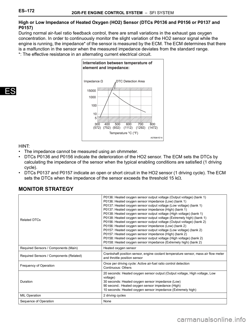
During normal air-fuel ratio feedback control, there are small variations in the exhaust gas oxygen
concentration. In order to continuously monitor the slight variation of the HO2 sensor signal while the
engine is running, the impedance* of the sensor is measured by the ECM. The ECM determines that there
is a malfunction in the sensor when the measured impedance deviates from the standard range.
*: The effective resistance in an alternating current electrical circuit.
HINT:
• The impedance cannot be measured using an ohmmeter.
• DTCs P0136 and P0156 indicate the deterioration of the HO2 sensor. The ECM sets the DTCs by
calculating the impedance of the sensor when the typical enabling conditions are satisfied (1 driving
cycle).
• DTCs P0137 and P0157 indicate an open or short circuit in the HO2 sensor (1 driving cycle). The ECM
sets the DTCs when the impedance of the sensor exceeds the threshold 15 k
.
MONITOR STRATEGY
Related DTCsP0136: Heated oxygen sensor output voltage (Output voltage) (bank 1)
P0136: Heated oxygen sensor impedance (Low) (bank 1)
P0137: Heated oxygen sensor output voltage (Low voltage) (bank 1)
P0137: Heated oxygen sensor impedance (High) (bank 1)
P0138: Heated oxygen sensor output voltage (High voltage) (bank 1)
P0138: Heated oxygen sensor output voltage (Extremely high) (bank 1)
P0156: Heated oxygen sensor output voltage (Output voltage) (bank 2)
P0156: Heated oxygen sensor impedance (Low) (bank 2)
P0157: Heated oxygen sensor output voltage (Low voltage) (bank 2)
P0157: Heated oxygen sensor impedance (High) (bank 2)
P0158: Heated oxygen sensor output voltage (High voltage) (bank 2)
P0158: Heated oxygen sensor impedance (Extremely high) (bank 2)
Required Sensors / Components (Main) Heated oxygen sensor
Required Sensors / Components (Related)Crankshaft position sensor, engine coolant temperature sensor, mass air flow meter
and throttle position sensor
Frequency of OperationOnce per driving cycle: Active air-fuel ratio control detection
Continuous: Others
Duration20 seconds: Heated oxygen sensor output (Output voltage, High voltage, Low
voltage)
30 seconds: Heated oxygen sensor impedance (Low)
90 second.: Heated oxygen sensor impedance (High)
10 seconds: Heated oxygen sensor impedance (Extremely high)
MIL Operation 2 driving cycles
Sequence of Operation None
A076841E14
Page 483 of 3000

2GR-FE ENGINE CONTROL SYSTEM – SFI SYSTEMES–177
ES
INSPECTION PROCEDURE
HINT:
For use of the intelligent tester only:
Malfunctioning areas can be identified by performing the A/F CONTROL function provided in the ACTIVE
TEST. The A/F CONTROL function can help to determine whether the Air-Fuel Ratio (A/F) sensor, Heated
Oxygen (HO2) sensor and other potential trouble areas are malfunctioning.
The following instructions describe how to conduct the A/F CONTROL operation using the intelligent
tester.
1. Connect the intelligent tester to the DLC3.
2. Start the engine and turn the tester on.
3. Warm up the engine at an engine speed of 2500 rpm for approximately 90 seconds.
4. Select the following menu items on the tester: DIAGNOSIS / ENHANCED OBD II / ACTIVE TEST / A/F
CONTROL.
5. Perform the A/F CONTROL operation with the engine in an idling condition (press the RIGHT or LEFT
button to change the fuel injection volume).
6. Monitor the voltage outputs of the A/F and HO2 sensors (AFS B1S1 and O2S B1S2 or AFS B2S1 and
O2S B2S2) displayed on the tester.
HINT:
• The A/F CONTROL operation lowers the fuel injection volume by 12.5% or increases the injection
volume by 25%.
• Each sensor reacts in accordance with increases and decreases in the fuel injection volume.
Standard voltage
NOTICE:
The Air-Fuel Ratio (A/F) sensor has an output delay of a few seconds and the Heated Oxygen
(HO2) sensor has a maximum output delay of approximately 20 seconds.
Tester Display (Sensor) Injection Volumes Status Voltages
AFS B1S1 or AFS B2S1 (A/F) +25% Rich Less than 3.0
AFS B1S1 or AFS B2S1 (A/F) -12.5% Lean More than 3.35
O2S B1S2 or O2S B2S2 (HO2) +25% Rich More than 0.55
O2S B1S2 or O2S B2S2 (HO2) -12.5% Lean Less than 0.4
CaseA/F Sensor (Sensor 1)
Output VoltageHO2 Sensor (Sensor 2)
Output VoltageMain Suspected
Trouble Area
1-