2007 TOYOTA SIENNA Oxygen sensors
[x] Cancel search: Oxygen sensorsPage 496 of 3000

ES–1902GR-FE ENGINE CONTROL SYSTEM – SFI SYSTEM
ES
TYPICAL ENABLING CONDITIONS
Fuel-trim:
TYPICAL MALFUNCTION THRESHOLDS
Fuel trim:
WIRING DIAGRAM
Refer to DTC P2195 (See page ES-359).
INSPECTION PROCEDURE
HINT:
For use of the intelligent tester only:
Malfunctioning areas can be identified by performing the A/F CONTROL function provided in the ACTIVE
TEST. The A/F CONTROL function can help to determine whether the Air-Fuel Ratio (A/F) sensor, Heated
Oxygen (HO2) sensor and other potential trouble areas are malfunctioning.
The following instructions describe how to conduct the A/F CONTROL operation using the intelligent
tester.
1. Connect the intelligent tester to the DLC3.
2. Start the engine and turn the tester on.
3. Warm up the engine at an engine speed of 2500 rpm for approximately 90 seconds.
4. Select the following menu items on the tester: DIAGNOSIS / ENHANCED OBD II / ACTIVE TEST / A/F
CONTROL.
5. Perform the A/F CONTROL operation with the engine in an idling condition (press the RIGHT or LEFT
button to change the fuel injection volume).
6. Monitor the voltage outputs of the A/F and HO2 sensors (AFS B1S1 and O2S B1S2 or AFS B2S1 and
O2S B2S2) displayed on the tester.
HINT:
• The A/F CONTROL operation lowers the fuel injection volume by 12.5% or increases the injection
volume by 25%.
• Each sensor reacts in accordance with increases and decreases in the fuel injection volume.
Standard voltage
The monitor will run whenever these DTCs are not
presentP0010, P0020 (VVT VSV1, 2), P0011, P0012 (VVT System-Advance, Retard),
P0021, P0022 (VVT System 2-Adavance, Retard), P0031, P0032, P0051, P0052 (A/
F Sensor Heater Sensor 1), P0100, P0101, P0102, P0103 (MAF Sensor), P0115,
P0116, P0117, P0118 (ECT Sensor), P0120, P0121, P0122, P0123, P0220, P0222,
P0223, P2135 (TP Sensor), P0125 (Insufficient ECT for Closed Loop), P0335 (CKP
Sensor), P0340 (CMP Sensor), P0351, P0352, P0353, P0354, P0356 (Ignitor),
P0500 (VSS)
Fuel system status Closed-loop
Battery voltage 11 V or more
Either of the following conditions is met Condition 1 or 2
1. Engine RPM Less than 1100 rpm
2. Intake air amount per revolution 0.22 g/rev or more
Catalyst monitor Not executed
EVAP purge-cut Executing
Either of the following conditions is met Condition 1 or 2
1. Average between short-term fuel trim and long-term
fuel trim35% or more at 80
C (176F) of ECT
2. Average between short-term fuel trim and long-term
fuel trim-35% or less at 80
C (176F) of ECT
Tester Display (Sensor) Injection Volumes Status Voltages
AFS B1S1 or AFS B2S1 (A/F) +25% Rich Less than 3.0
Page 615 of 3000

ES–3222GR-FE ENGINE CONTROL SYSTEM – SFI SYSTEM
ES
DESCRIPTION
The ECM continuously monitors its internal processors (CPUs), A/F sensor transistors and heated oxygen
sensor (HO2S) transistors. This self-check ensures that the ECM is functioning properly. These are
diagnosed by internal "mirroring" of the main and sub CPUs to detect the processors error. If outputs from
the processors deviate from the standards, the ECM will illuminate the MIL and set a DTC immediately.
MONITOR STRATEGY
TYPICAL ENABLING CONDITIONS
TYPICAL MALFUNCTION THRESHOLDS
INSPECTION PROCEDURE
(a) Allow the engine to idle.
(b) Check for exhaust gas leak around the heated oxygen
sensor.
OK:
No leak from the heated oxygen sensor.
NG
DTC P0606 ECM / PCM Processor
DTC DTC Setting Condition Trouble Area
P0606• ECM CPUs malfunction
• A/F sensor transistors malfunction
• HO2S transistors malfunction• Exhaust gas leak
•HO2 Sensor
•ECM
Related DTC P0606: ECM range check
Required sensors/Components (main) ECM
Required sensors/Components (sub)APP sensor, TP sensor, Brake switch, Cruise control, A/F sensor,
HO2 sensor
Frequency of Operation Continuous
Duration 60 seconds
MIL Operation Immediate
Sequence of Operation None
Monitor runs whenever the following DTCs are not present None
Engine Running
Estimated A/F sensor temperature 450 to 800
C (842 to 1472F)
Estimated HO2S temperature 450 to 800
C (842 to 1472F)
Difference of main APP and sub APP 0.3 V or more
Difference of main TP and sub TP 0.3 V or more
Difference of main brake switch signal and sub brake switch signal Different
Cruise control Fail
A/F sensor transistors Fail
HO2S transistors Fail
1INSPECT FOR EXHAUST GAS LEAK
REPAIR OR REPLACE EXHAUST GAS
LEAKAGE POINT
Page 616 of 3000
2GR-FE ENGINE CONTROL SYSTEM – SFI SYSTEMES–323
ES
OK
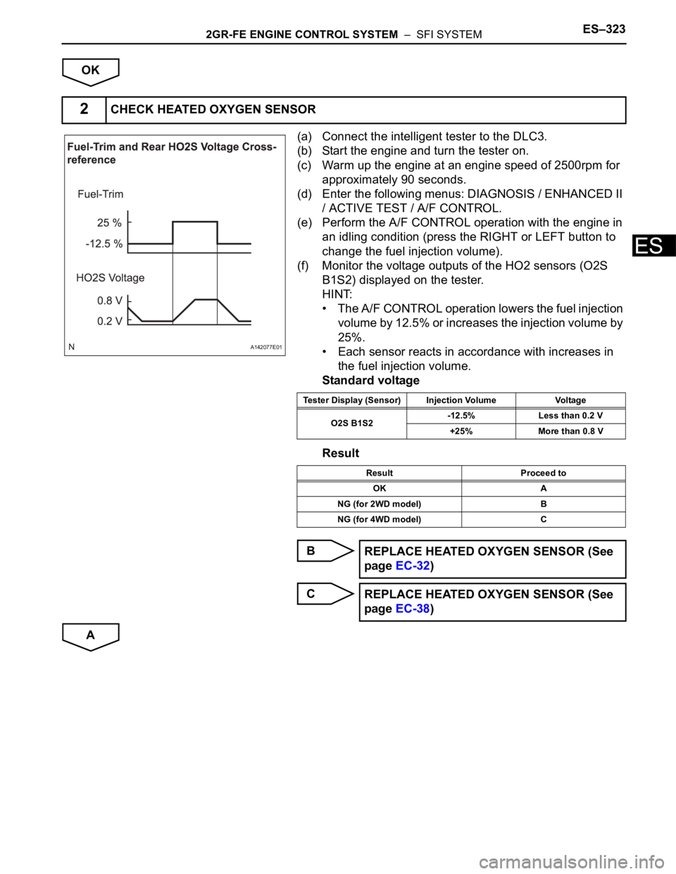
(a) Connect the intelligent tester to the DLC3.
(b) Start the engine and turn the tester on.
(c) Warm up the engine at an engine speed of 2500rpm for
approximately 90 seconds.
(d) Enter the following menus: DIAGNOSIS / ENHANCED II
/ ACTIVE TEST / A/F CONTROL.
(e) Perform the A/F CONTROL operation with the engine in
an idling condition (press the RIGHT or LEFT button to
change the fuel injection volume).
(f) Monitor the voltage outputs of the HO2 sensors (O2S
B1S2) displayed on the tester.
HINT:
• The A/F CONTROL operation lowers the fuel injection
volume by 12.5% or increases the injection volume by
25%.
• Each sensor reacts in accordance with increases in
the fuel injection volume.
Standard voltage
Result
B
C
A
2CHECK HEATED OXYGEN SENSOR
A142077E01
Tester Display (Sensor) Injection Volume Voltage
O2S B1S2-12.5% Less than 0.2 V
+25% More than 0.8 V
Result Proceed to
OK A
NG (for 2WD model) B
NG (for 4WD model) C
REPLACE HEATED OXYGEN SENSOR (See
page EC-32)
REPLACE HEATED OXYGEN SENSOR (See
page EC-38)
Page 662 of 3000

2GR-FE ENGINE CONTROL SYSTEM – SFI SYSTEMES–369
ES
9. Drive the vehicle at a proper vehicle speed to perform fuel-cut operation (refer to the following HINT)
(Procedure "D").
HINT:
Fuel-cut is performed when the following conditions are met:
• Accelerator pedal is fully released.
• Engine speed is 2500 rpm or more (fuel injection resumes at 1000 rpm).
10. Accelerate the vehicle to 40 mph (64 km/h) or more by depressing the accelerator pedal for at least 10
seconds (Procedure "E").
11. Soon after performing procedure "J" on the previous page, release the accelerator pedal for at least 4
seconds without depressing the brake pedal, in order to execute fuel-cut control (Procedure "F").
12. Allow the vehicle to decelerate until the vehicle speed declines to less than 6 mph (10 km/h).
13. Repeat procedures from "H" through "K" in this section at least 3 times per driving cycle.
HINT:
Completion of all A/F sensor monitors is required to change the value in TEST RESULT.
CAUTION:
Strictly observe posted speed limits, traffic laws, and road conditions when performing these
driving patterns.
INSPECTION PROCEDURE
HINT:
Malfunctioning areas can be identified by performing the A/F CONTROL function provided in the ACTIVE
TEST. The A/F CONTROL function can help to determine whether the Air-Fuel Ratio (A/F) sensor, Heated
Oxygen (HO2) sensor and other potential trouble areas are malfunctioning.
The following instructions describe how to conduct the A/F CONTROL operation using an intelligent
tester.
(a) Connect the intelligent tester to the DLC3.
(b) Start the engine and turn the tester on.
(c) Warm up the engine at an engine speed of 2500 rpm for approximately 90 seconds.
(d) Select the following menu items on the tester: DIAGNOSIS / ENHANCED OBD II / ACTIVE TEST / A/
F CONTROL.
(e) Perform the A/F CONTROL operation with the engine in an idling condition (press the RIGHT or LEFT
button to change the fuel injection volume).
(f) Monitor the voltage outputs of the A/F and HO2 sensors (AFS B1S1 and O2S B1S2 or AFS B2S1 and
O2S B2S2) displayed on the tester.
HINT:
• The A/F CONTROL operation lowers the fuel injection volume by 12.5% or increases the injection
volume by 25%.
• Each sensor reacts in accordance with increases and decreases in the fuel injection volume.
Standard voltage
NOTICE:
The Air-Fuel Ratio (A/F) sensor has an output delay of a few seconds and the Heated Oxygen
(HO2) sensor has a maximum output delay of approximately 20 seconds.
Tester Display (Sensor) Injection Volumes Status Voltages
AFS B1S1 or AFS B2S1 (A/F) +25% Rich Less than 3.0
AFS B1S1 or AFS B2S1 (A/F) -12.5% Lean More than 3.35
O2S B1S2 or O2S B2S2 (HO2) +25% Rich More than 0.55
O2S B1S2 or O2S B2S2 (HO2) -12.5% Lean Less than 0.4
Page 676 of 3000
2GR-FE ENGINE CONTROL SYSTEM – SFI SYSTEMES–383
ES
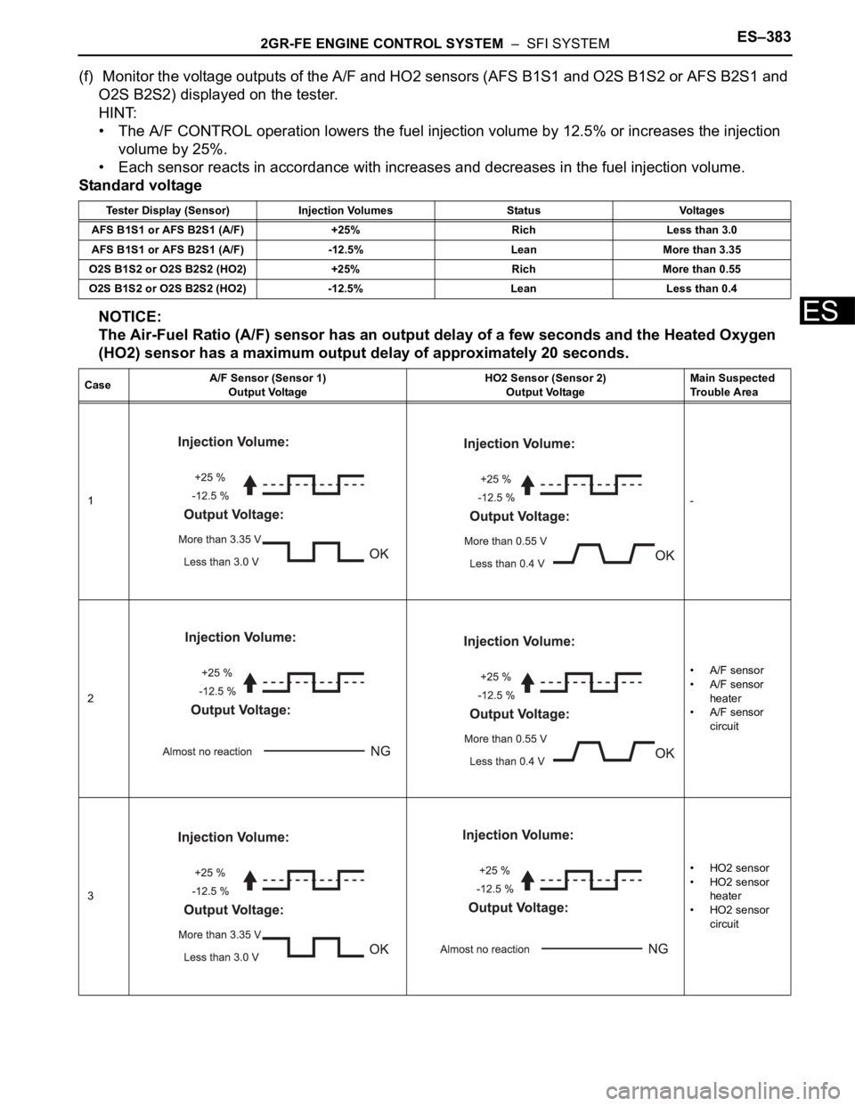
(f) Monitor the voltage outputs of the A/F and HO2 sensors (AFS B1S1 and O2S B1S2 or AFS B2S1 and
O2S B2S2) displayed on the tester.
HINT:
• The A/F CONTROL operation lowers the fuel injection volume by 12.5% or increases the injection
volume by 25%.
• Each sensor reacts in accordance with increases and decreases in the fuel injection volume.
Standard voltage
NOTICE:
The Air-Fuel Ratio (A/F) sensor has an output delay of a few seconds and the Heated Oxygen
(HO2) sensor has a maximum output delay of approximately 20 seconds.
Tester Display (Sensor) Injection Volumes Status Voltages
AFS B1S1 or AFS B2S1 (A/F) +25% Rich Less than 3.0
AFS B1S1 or AFS B2S1 (A/F) -12.5% Lean More than 3.35
O2S B1S2 or O2S B2S2 (HO2) +25% Rich More than 0.55
O2S B1S2 or O2S B2S2 (HO2) -12.5% Lean Less than 0.4
CaseA/F Sensor (Sensor 1)
Output VoltageHO2 Sensor (Sensor 2)
Output VoltageMain Suspected
Trouble Area
1-
2•A/F sensor
•A/F sensor
heater
•A/F sensor
circuit
3•HO2 sensor
• HO2 sensor
heater
• HO2 sensor
circuit
Page 690 of 3000
2GR-FE ENGINE CONTROL SYSTEM – SFI SYSTEMES–397
ES
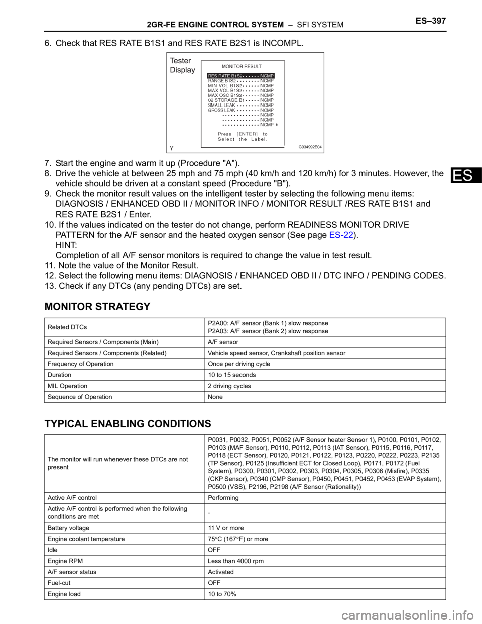
6. Check that RES RATE B1S1 and RES RATE B2S1 is INCOMPL.
7. Start the engine and warm it up (Procedure "A").
8. Drive the vehicle at between 25 mph and 75 mph (40 km/h and 120 km/h) for 3 minutes. However, the
vehicle should be driven at a constant speed (Procedure "B").
9. Check the monitor result values on the intelligent tester by selecting the following menu items:
DIAGNOSIS / ENHANCED OBD II / MONITOR INFO / MONITOR RESULT /RES RATE B1S1 and
RES RATE B2S1 / Enter.
10. If the values indicated on the tester do not change, perform READINESS MONITOR DRIVE
PATTERN for the A/F sensor and the heated oxygen sensor (See page ES-22).
HINT:
Completion of all A/F sensor monitors is required to change the value in test result.
11. Note the value of the Monitor Result.
12. Select the following menu items: DIAGNOSIS / ENHANCED OBD II / DTC INFO / PENDING CODES.
13. Check if any DTCs (any pending DTCs) are set.
MONITOR STRATEGY
TYPICAL ENABLING CONDITIONS
Related DTCsP2A00: A/F sensor (Bank 1) slow response
P2A03: A/F sensor (Bank 2) slow response
Required Sensors / Components (Main) A/F sensor
Required Sensors / Components (Related) Vehicle speed sensor, Crankshaft position sensor
Frequency of Operation Once per driving cycle
Duration 10 to 15 seconds
MIL Operation 2 driving cycles
Sequence of Operation None
The monitor will run whenever these DTCs are not
presentP0031, P0032, P0051, P0052 (A/F Sensor heater Sensor 1), P0100, P0101, P0102,
P0103 (MAF Sensor), P0110, P0112, P0113 (IAT Sensor), P0115, P0116, P0117,
P0118 (ECT Sensor), P0120, P0121, P0122, P0123, P0220, P0222, P0223, P2135
(TP Sensor), P0125 (Insufficient ECT for Closed Loop), P0171, P0172 (Fuel
System), P0300, P0301, P0302, P0303, P0304, P0305, P0306 (Misfire), P0335
(CKP Sensor), P0340 (CMP Sensor), P0450, P0451, P0452, P0453 (EVAP System),
P0500 (VSS), P2196, P2198 (A/F Sensor (Rationality))
Active A/F control Performing
Active A/F control is performed when the following
conditions are met-
Battery voltage 11 V or more
Engine coolant temperature 75
C (167F) or more
Idle OFF
Engine RPM Less than 4000 rpm
A/F sensor status Activated
Fuel-cut OFF
Engine load 10 to 70%
G034992E04
Page 691 of 3000

ES–3982GR-FE ENGINE CONTROL SYSTEM – SFI SYSTEM
ES
TYPICAL MALFUNCTION THRESHOLDS
MONITOR RESULT
Refer to CHECKING MONITOR STATUS (See page ES-19).
WIRING DIAGRAM
Refer to DTC P2195 (See page ES-359).
INSPECTION PROCEDURE
HINT:
Malfunctioning areas can be identified by performing the A/F CONTROL function provided in the ACTIVE
TEST. The A/F CONTROL function can help to determine whether the Air-Fuel Ratio (A/F) sensor, Heated
Oxygen (HO2) sensor and other potential trouble areas are malfunctioning.
The following instructions describe how to conduct the A/F CONTROL operation using an intelligent
tester.
(a) Connect the intelligent tester to the DLC3.
(b) Start the engine and turn the tester on.
(c) Warm up the engine at an engine speed of 2500 rpm for approximately 90 seconds.
(d) Select the following menu items on the tester: DIAGNOSIS / ENHANCED OBD II / ACTIVE TEST / A/
F CONTROL.
(e) Perform the A/F CONTROL operation with the engine in an idling condition (press the RIGHT or LEFT
button to change the fuel injection volume).
(f) Monitor the voltage outputs of the A/F and HO2 sensors (AFS B1S1 and O2S B1S2 or AFS B2S1 and
O2S B2S2) displayed on the tester.
HINT:
• The A/F CONTROL operation lowers the fuel injection volume by 12.5% or increases the injection
volume by 25%.
• Each sensor reacts in accordance with increases and decreases in the fuel injection volume.
Standard voltage
NOTICE:
The Air-Fuel Ratio (A/F) sensor has an output delay of a few seconds and the Heated Oxygen
(HO2) sensor has a maximum output delay of approximately 20 seconds.
Shift position 2 or more
Catalyst monitor Not yet
MAF 2.5 to 15 g/s
Response rate deterioration level Less than 0.18 V
Tester Display (Sensor) Injection Volumes Status Voltages
AFS B1S1 or AFS B2S1 (A/F) +25% Rich Less than 3.0
AFS B1S1 or AFS B2S1 (A/F) -12.5% Lean More than 3.35
O2S B1S2 or O2S B2S2 (HO2) +25% Rich More than 0.55
O2S B1S2 or O2S B2S2 (HO2) -12.5% Lean Less than 0.4
Page 816 of 3000

ES–362GR-FE ENGINE CONTROL SYSTEM – SFI SYSTEM
ES
M+ (E9-5) - ME01 (E10-3) B - W-BThrottle drive motor
operation signal (positive
terminal)Idling with warm enginePluse generation
(see waveform 9)
E02 (E9-6) - Body ground W-B - -Earth (ground) circuit of
ECMAlways Below 1 V
E01 (E9-7) - Body ground W-B - -Earth (ground) circuit of
ECMAlways Below 1 V
IGT1 (E9-8) - E1 (E11-1)
IGT2 (E9-9) - E1 (E11-1)
IGT3 (E9-10) - E1 (E11-1)
IGT4 (E9-11) - E1 (E11-1)
IGT5 (E9-12) - E1 (E11-1)
IGT6 (E9-13) - E1 (E11-1)R-L - BR
P - BR
Y- B - B R
L-Y - BR
G-Y - BR
L-R - BRIgnition coil with igniter
(ignition signal)IdlingPulse generation
(see waveform 6)
GE01 (E9-17) - E1 (E11-1) - - BRShielded earth (ground)
circuit of throttle drive
motorAlways Below 1 V
OX1B (E9-18) - E2 (E9-28)
OX2B (E10-33) - E2 (E9-28)W - BR
B - BRHeated oxygen sensor
signalWith engine speed at 2500 rpm
for 2 minutes after warming upPulse generation
(see waveform 2)
VTA2 (E9-19) - E2 (E9-28) B-R - BRThrottle position sensor
signal (for sensor
malfunction detection)Ignition switch ON, Accelerator
pedal fully released2.1 to 3.1 V
VTA2 (E9-19) - E2 (E9-28) B-R - BRThrottle position sensor
signal (for sensor
malfunction detection)Ignition switch ON, Accelerator
pedal fully depressed4.5 to 5.0 V
VTA1 (E9-20) - E2 (E9-28) LG - BRThrottle position sensor
signal (for engine control)Ignition switch ON, Throttle valve
fully closed0.5 to 1.2 V
VTA1 (E9-20) - E2 (E9-28) LG - BRThrottle position sensor
signal (for engine control)Ignition switch ON, Throttle valve
fully open3.2 to 4.8 V
THW (E9-21) - E2 (E9-28) G-B - BREngine coolant
temperature sensor signalIdling, Engine coolant
temperature 80
C (176F)0.2 to 1.0 V
THA (E9-22) - E2 (E9-28) L-B - BRIntake air temperature
sensor signalIdling, Intake air temperature
20
C (68F)0.5 to 3.4 V
VC (E9-23) - E2 (E9-28) Y - BRPower source of sensors
(specific voltage)Ignition switch ON 4.5 to 5.0 V
IGF1 (E9-24) - E1 (E11-1) W-R - BRIgnition coil with igniter
(ignition confirmation
signal)Ignition switch ON 4.5 to 5.0 V
IGF1 (E9-24) - E1 (E11-1) W-R - BRIgnition coil with igniter
(ignition confirmation
signal)IdlingPulse generation
(see waveform 6)
AICV (E9-27) - E1 (E11-1) W - BRVSV for Air intake control
system operation signalIgnition switch ON 9 to 14 V
E2 (E9-28) - E1 (E11-1) BR - BREarth (ground) circuit of
sensors for ETCSAlways Below 1 V
E2G (E9-29) - E1 (E11-1) L-W - BREarth (ground) circuit of
sensor for mass air flow
meterAlways Below 1 V
VG (E9-30) - E2G (E9-29) R - L-WMass Air Flow (MAF)
meter signalIdling, Shift lever position P or N,
A/C switch OFF0.5 to 3.0 V
ACIS (E9-33) - E1 (E11-1) R-Y - BRVSV for ACIS (Acoustic
Control Induction System)
operation signalIgnition switch ON 9 to 14 V
PRG (E9-34) - E1 (E11-1) G - BRPurge VSV for EVAP
system operation signalIgnition switch ON 9 to 14 V
PRG (E9-34) - E1 (E11-1) G - BRPurge VSV for EVAP
system operation signalIdlingPulse generation
(see waveform 7)
HA2A (E10-1) - E05 (E10-6) Y - W-BA/F sensor heater
operation signalIdling Below 3.0 V Symbols (Terminal No.) Wiring Colors Terminal Descriptions ConditionsSpecified
Condition