2007 TOYOTA SIENNA stop light switch assembly
[x] Cancel search: stop light switch assemblyPage 185 of 3000
BRAKE – BRAKE PEDALBR–11
BR
REMOVAL
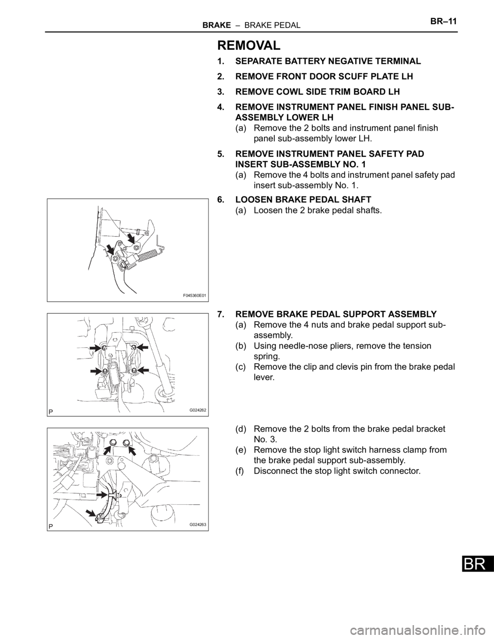
1. SEPARATE BATTERY NEGATIVE TERMINAL
2. REMOVE FRONT DOOR SCUFF PLATE LH
3. REMOVE COWL SIDE TRIM BOARD LH
4. REMOVE INSTRUMENT PANEL FINISH PANEL SUB-
ASSEMBLY LOWER LH
(a) Remove the 2 bolts and instrument panel finish
panel sub-assembly lower LH.
5. REMOVE INSTRUMENT PANEL SAFETY PAD
INSERT SUB-ASSEMBLY NO. 1
(a) Remove the 4 bolts and instrument panel safety pad
insert sub-assembly No. 1.
6. LOOSEN BRAKE PEDAL SHAFT
(a) Loosen the 2 brake pedal shafts.
7. REMOVE BRAKE PEDAL SUPPORT ASSEMBLY
(a) Remove the 4 nuts and brake pedal support sub-
assembly.
(b) Using needle-nose pliers, remove the tension
spring.
(c) Remove the clip and clevis pin from the brake pedal
lever.
(d) Remove the 2 bolts from the brake pedal bracket
No. 3.
(e) Remove the stop light switch harness clamp from
the brake pedal support sub-assembly.
(f) Disconnect the stop light switch connector.
F045360E01
G024262
G024263
Page 186 of 3000
BR–12BRAKE – BRAKE PEDAL
BR
DISASSEMBLY
1. REMOVE STOP LIGHT SWITCH ASSEMBLY
(a) Turn the stop light switch assembly
counterclockwise and remove the stop light switch
assembly.
(b) Remove the stop light switch mounting adjuster
from the brake pedal support sub-assembly.
2. REMOVE STOP LIGHT SWITCH CUSHION
(a) Remove the stop light switch cushion from the brake
pedal sub-assembly.
3. REMOVE BRAKE PEDAL
(a) Remove the 2 brake pedal shafts, 2 nuts and brake
pedal from the brake pedal support sub-assembly.
4. REMOVE BRAKE PEDAL BUSH
(a) Remove the 4 brake pedal bushes from the brake
pedal.
5. REMOVE BRAKE PEDAL SHAFT COLLAR
(a) Remove the 2 brake pedal shaft collars from the
brake pedal.
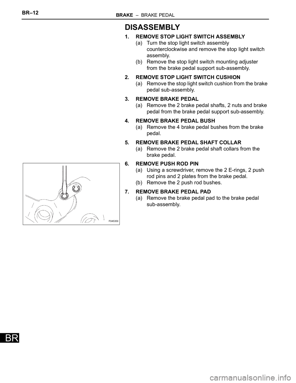
6. REMOVE PUSH ROD PIN
(a) Using a screwdriver, remove the 2 E-rings, 2 push
rod pins and 2 plates from the brake pedal.
(b) Remove the 2 push rod bushes.
7. REMOVE BRAKE PEDAL PAD
(a) Remove the brake pedal pad to the brake pedal
sub-assembly.
F045359
Page 591 of 3000
ES–2982GR-FE ENGINE CONTROL SYSTEM – SFI SYSTEM
ES
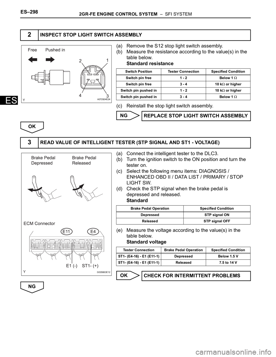
(a) Remove the S12 stop light switch assembly.
(b) Measure the resistance according to the value(s) in the
table below.
Standard resistance
(c) Reinstall the stop light switch assembly.
NG
OK
(a) Connect the intelligent tester to the DLC3.
(b) Turn the ignition switch to the ON position and turn the
tester on.
(c) Select the following menu items: DIAGNOSIS /
ENHANCED OBD II / DATA LIST / PRIMARY / STOP
LIGHT SW.
(d) Check the STP signal when the brake pedal is
depressed and released.
Standard
(e) Measure the voltage according to the value(s) in the
table below.
Standard voltage
OK
NG
2INSPECT STOP LIGHT SWITCH ASSEMBLY
A072924E24
Switch Position Tester Connection Specified Condition
Switch pin free 1 - 2 Below 1
Switch pin free 3 - 4 10 k or higher
Switch pin pushed in 1 - 2 10 k
or higher
Switch pin pushed in 3 - 4 Below 1
REPLACE STOP LIGHT SWITCH ASSEMBLY
3READ VALUE OF INTELLIGENT TESTER (STP SIGNAL AND ST1 - VOLTAGE)
G035663E12
Brake Pedal Operation Specified Condition
Depressed STP signal ON
Released STP signal OFF
Tester Connection Brake Pedal Operation Specified Condition
ST1- (E4-16) - E1 (E11-1) Depressed Below 1.5 V
ST1- (E4-16) - E1 (E11-1) Released 7.5 to 14 V
CHECK FOR INTERMITTENT PROBLEMS
Page 1408 of 3000
AX–42U151E AUTOMATIC TRANSAXLE – AUTOMATIC TRANSAXLE SYSTEM
AX
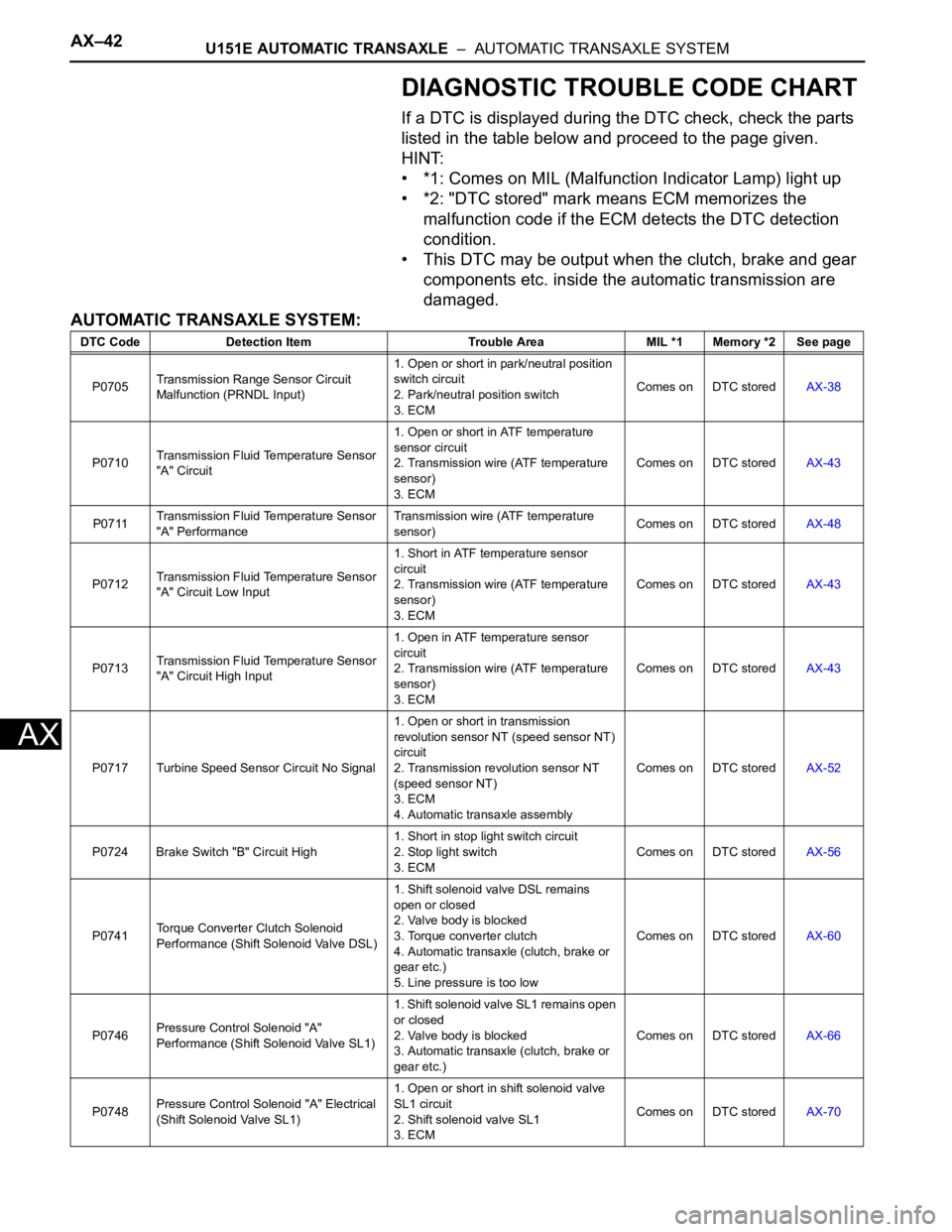
DIAGNOSTIC TROUBLE CODE CHART
If a DTC is displayed during the DTC check, check the parts
listed in the table below and proceed to the page given.
HINT:
• *1: Comes on MIL (Malfunction Indicator Lamp) light up
• *2: "DTC stored" mark means ECM memorizes the
malfunction code if the ECM detects the DTC detection
condition.
• This DTC may be output when the clutch, brake and gear
components etc. inside the automatic transmission are
damaged.
AUTOMATIC TRANSAXLE SYSTEM:
DTC Code Detection Item Trouble Area MIL *1 Memory *2 See page
P0705Transmission Range Sensor Circuit
Malfunction (PRNDL Input)1. Open or short in park/neutral position
switch circuit
2. Park/neutral position switch
3. ECMComes on DTC storedAX-38
P0710Transmission Fluid Temperature Sensor
"A" Circuit1. Open or short in ATF temperature
sensor circuit
2. Transmission wire (ATF temperature
sensor)
3. ECMComes on DTC storedAX-43
P0711Transmission Fluid Temperature Sensor
"A" PerformanceTransmission wire (ATF temperature
sensor)Comes on DTC storedAX-48
P0712Transmission Fluid Temperature Sensor
"A" Circuit Low Input1. Short in ATF temperature sensor
circuit
2. Transmission wire (ATF temperature
sensor)
3. ECMComes on DTC storedAX-43
P0713Transmission Fluid Temperature Sensor
"A" Circuit High Input1. Open in ATF temperature sensor
circuit
2. Transmission wire (ATF temperature
sensor)
3. ECMComes on DTC storedAX-43
P0717 Turbine Speed Sensor Circuit No Signal1. Open or short in transmission
revolution sensor NT (speed sensor NT)
circuit
2. Transmission revolution sensor NT
(speed sensor NT)
3. ECM
4. Automatic transaxle assemblyComes on DTC storedAX-52
P0724 Brake Switch "B" Circuit High1. Short in stop light switch circuit
2. Stop light switch
3. ECMComes on DTC storedAX-56
P0741Torque Converter Clutch Solenoid
Performance (Shift Solenoid Valve DSL)1. Shift solenoid valve DSL remains
open or closed
2. Valve body is blocked
3. Torque converter clutch
4. Automatic transaxle (clutch, brake or
gear etc.)
5. Line pressure is too lowComes on DTC storedAX-60
P0746Pressure Control Solenoid "A"
Performance (Shift Solenoid Valve SL1)1. Shift solenoid valve SL1 remains open
or closed
2. Valve body is blocked
3. Automatic transaxle (clutch, brake or
gear etc.)Comes on DTC storedAX-66
P0748Pressure Control Solenoid "A" Electrical
(Shift Solenoid Valve SL1)1. Open or short in shift solenoid valve
SL1 circuit
2. Shift solenoid valve SL1
3. ECMComes on DTC storedAX-70
Page 1431 of 3000
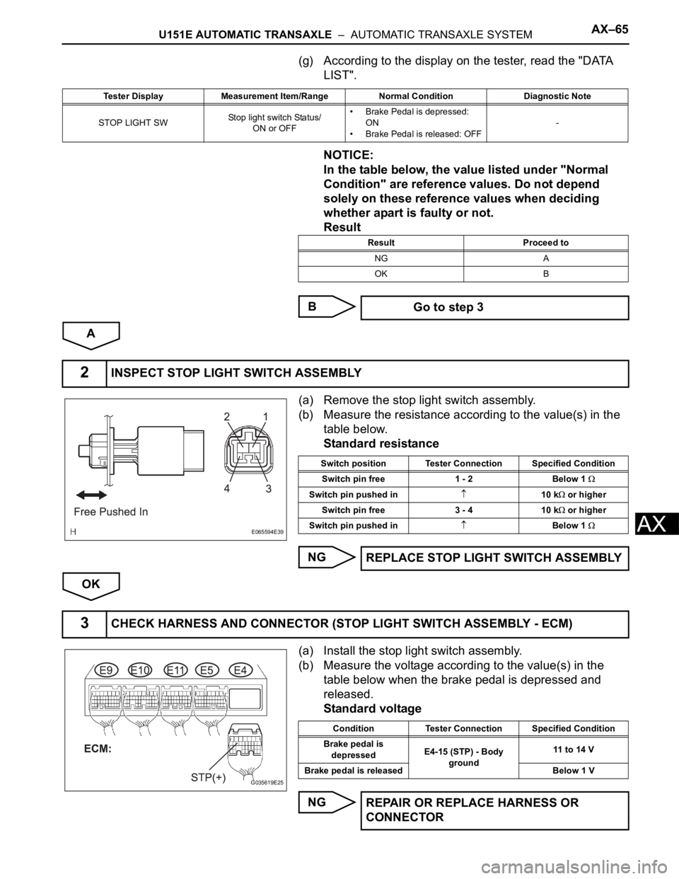
U151E AUTOMATIC TRANSAXLE – AUTOMATIC TRANSAXLE SYSTEMAX–65
AX
(g) According to the display on the tester, read the "DATA
LIST".
NOTICE:
In the table below, the value listed under "Normal
Condition" are reference values. Do not depend
solely on these reference values when deciding
whether apart is faulty or not.
Result
B
A
(a) Remove the stop light switch assembly.
(b) Measure the resistance according to the value(s) in the
table below.
Standard resistance
NG
OK
(a) Install the stop light switch assembly.
(b) Measure the voltage according to the value(s) in the
table below when the brake pedal is depressed and
released.
Standard voltage
NG
Tester Display Measurement Item/Range Normal Condition Diagnostic Note
STOP LIGHT SWStop light switch Status/
ON or OFF• Brake Pedal is depressed:
ON
• Brake Pedal is released: OFF-
Result Proceed to
NG A
OK B
Go to step 3
2INSPECT STOP LIGHT SWITCH ASSEMBLY
E065594E39
Switch position Tester Connection Specified Condition
Switch pin free 1 - 2 Below 1
Switch pin pushed in10 k or higher
Switch pin free 3 - 4 10 k
or higher
Switch pin pushed in
Below 1
REPLACE STOP LIGHT SWITCH ASSEMBLY
3CHECK HARNESS AND CONNECTOR (STOP LIGHT SWITCH ASSEMBLY - ECM)
G035619E25
Condition Tester Connection Specified Condition
Brake pedal is
depressedE4-15 (STP) - Body
ground11 to 14 V
Brake pedal is released Below 1 V
REPAIR OR REPLACE HARNESS OR
CONNECTOR
Page 1714 of 3000
AX–42U151F AUTOMATIC TRANSAXLE – AUTOMATIC TRANSAXLE SYSTEM
AX
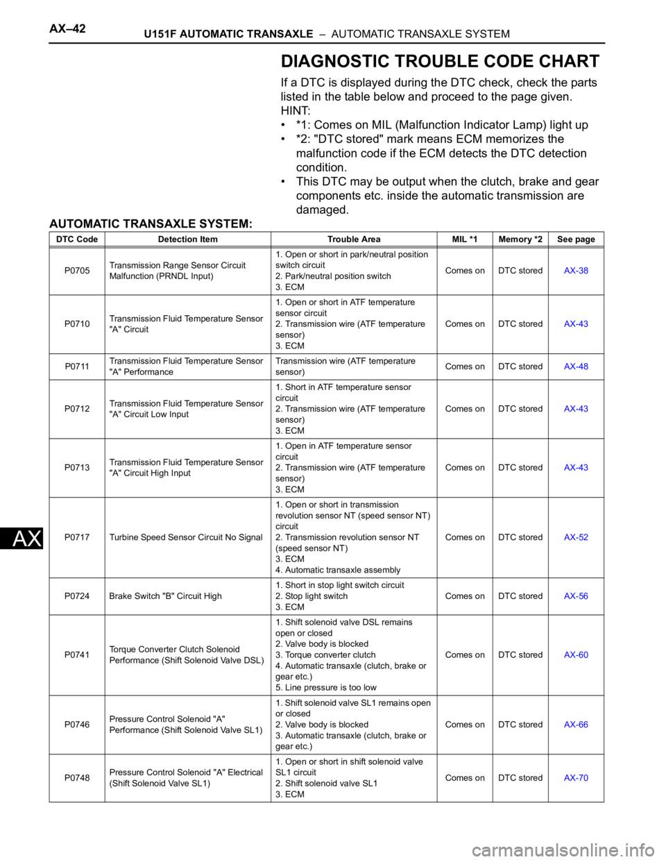
DIAGNOSTIC TROUBLE CODE CHART
If a DTC is displayed during the DTC check, check the parts
listed in the table below and proceed to the page given.
HINT:
• *1: Comes on MIL (Malfunction Indicator Lamp) light up
• *2: "DTC stored" mark means ECM memorizes the
malfunction code if the ECM detects the DTC detection
condition.
• This DTC may be output when the clutch, brake and gear
components etc. inside the automatic transmission are
damaged.
AUTOMATIC TRANSAXLE SYSTEM:
DTC Code Detection Item Trouble Area MIL *1 Memory *2 See page
P0705Transmission Range Sensor Circuit
Malfunction (PRNDL Input)1. Open or short in park/neutral position
switch circuit
2. Park/neutral position switch
3. ECMComes on DTC storedAX-38
P0710Transmission Fluid Temperature Sensor
"A" Circuit1. Open or short in ATF temperature
sensor circuit
2. Transmission wire (ATF temperature
sensor)
3. ECMComes on DTC storedAX-43
P0711Transmission Fluid Temperature Sensor
"A" PerformanceTransmission wire (ATF temperature
sensor)Comes on DTC storedAX-48
P0712Transmission Fluid Temperature Sensor
"A" Circuit Low Input1. Short in ATF temperature sensor
circuit
2. Transmission wire (ATF temperature
sensor)
3. ECMComes on DTC storedAX-43
P0713Transmission Fluid Temperature Sensor
"A" Circuit High Input1. Open in ATF temperature sensor
circuit
2. Transmission wire (ATF temperature
sensor)
3. ECMComes on DTC storedAX-43
P0717 Turbine Speed Sensor Circuit No Signal1. Open or short in transmission
revolution sensor NT (speed sensor NT)
circuit
2. Transmission revolution sensor NT
(speed sensor NT)
3. ECM
4. Automatic transaxle assemblyComes on DTC storedAX-52
P0724 Brake Switch "B" Circuit High1. Short in stop light switch circuit
2. Stop light switch
3. ECMComes on DTC storedAX-56
P0741Torque Converter Clutch Solenoid
Performance (Shift Solenoid Valve DSL)1. Shift solenoid valve DSL remains
open or closed
2. Valve body is blocked
3. Torque converter clutch
4. Automatic transaxle (clutch, brake or
gear etc.)
5. Line pressure is too lowComes on DTC storedAX-60
P0746Pressure Control Solenoid "A"
Performance (Shift Solenoid Valve SL1)1. Shift solenoid valve SL1 remains open
or closed
2. Valve body is blocked
3. Automatic transaxle (clutch, brake or
gear etc.)Comes on DTC storedAX-66
P0748Pressure Control Solenoid "A" Electrical
(Shift Solenoid Valve SL1)1. Open or short in shift solenoid valve
SL1 circuit
2. Shift solenoid valve SL1
3. ECMComes on DTC storedAX-70
Page 1737 of 3000
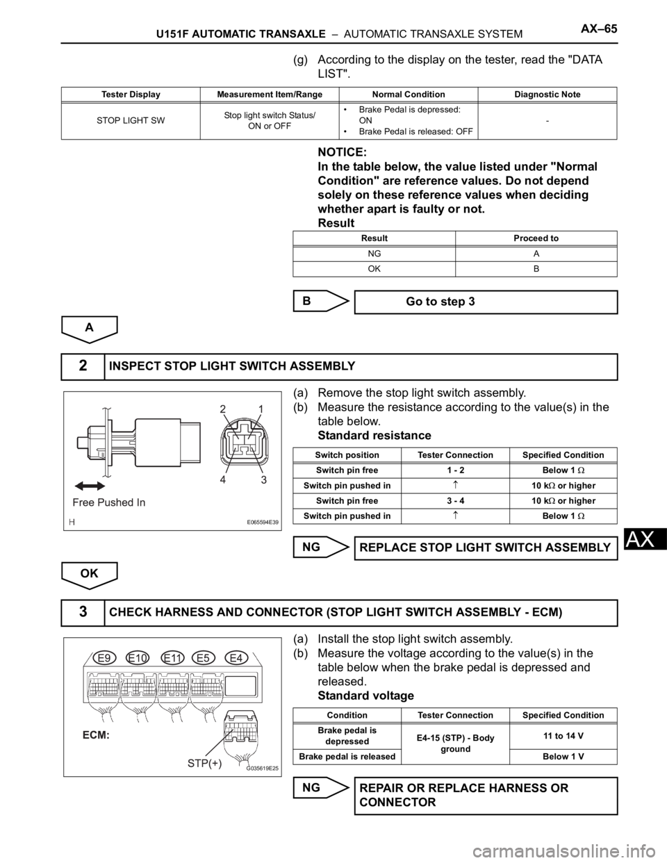
U151F AUTOMATIC TRANSAXLE – AUTOMATIC TRANSAXLE SYSTEMAX–65
AX
(g) According to the display on the tester, read the "DATA
LIST".
NOTICE:
In the table below, the value listed under "Normal
Condition" are reference values. Do not depend
solely on these reference values when deciding
whether apart is faulty or not.
Result
B
A
(a) Remove the stop light switch assembly.
(b) Measure the resistance according to the value(s) in the
table below.
Standard resistance
NG
OK
(a) Install the stop light switch assembly.
(b) Measure the voltage according to the value(s) in the
table below when the brake pedal is depressed and
released.
Standard voltage
NG
Tester Display Measurement Item/Range Normal Condition Diagnostic Note
STOP LIGHT SWStop light switch Status/
ON or OFF• Brake Pedal is depressed:
ON
• Brake Pedal is released: OFF-
Result Proceed to
NG A
OK B
Go to step 3
2INSPECT STOP LIGHT SWITCH ASSEMBLY
E065594E39
Switch position Tester Connection Specified Condition
Switch pin free 1 - 2 Below 1
Switch pin pushed in10 k or higher
Switch pin free 3 - 4 10 k
or higher
Switch pin pushed in
Below 1
REPLACE STOP LIGHT SWITCH ASSEMBLY
3CHECK HARNESS AND CONNECTOR (STOP LIGHT SWITCH ASSEMBLY - ECM)
G035619E25
Condition Tester Connection Specified Condition
Brake pedal is
depressedE4-15 (STP) - Body
ground11 to 14 V
Brake pedal is released Below 1 V
REPAIR OR REPLACE HARNESS OR
CONNECTOR
Page 2360 of 3000

BRAKE CONTROL – ANTI-LOCK BRAKE SYSTEMBC–9
BC
PROBLEM SYMPTOMS TABLE
If there are no DTCs output but the problem still occurs,
check the circuits for each problem symptom in the order
given in the table below and proceed to the relevant
troubleshooting page.
NOTICE:
When replacing the brake actuator assembly, sensor,
etc., turn the ignition switch off.
HINT:
Inspect the fuse and relay before investigating the suspected
areas as shown in the table below. Inspect each malfunction
circuit in numerical order for the corresponding symptom.
Anti-lock brake system:
Symptom Suspected Area See page
ABS does not operate1. Check the DTC again and make sure that the normal
system code is output.BC-10
2. IG power source circuitBC-37
3. Front speed sensor circuitBC-17
4. Rear speed sensor circuitBC-23
5. Check the brake actuator with the intelligent tester. If
abnormal, check the hydraulic circuit for leakage.BC-183
6. If the symptoms still occur even after the above circuits in
suspected areas have been inspected and proved to be
normal, replace the brake actuator assembly.BC-184
ABS does not operate efficiently1. Check the DTC again and make sure that the normal
system code is output.BC-10
2. Front speed sensor circuitBC-17
3. Rear speed sensor circuitBC-23
4. Stop light switch circuitBC-41
5. Check the brake actuator with intelligent tester. If abnormal,
check that hydraulic circuit for leakage.BC-183
6. If the symptoms still occur even after the above circuits in
suspected areas have been inspected and proved to be
normal, replace the brake actuator assembly.BC-184
ABS warning light abnormal (Remains on)1. ABS warning light circuitBC-47
2. Brake actuator assemblyBC-184
ABS warning light abnormal (Does not come on)1. ABS warning light circuitBC-50
2. Brake actuator assemblyBC-184
BRAKE warning light abnormal (Remains on)1. BRAKE warning light circuitBC-52
2. Brake actuator assemblyBC-184
BRAKE warning light abnormal (Does not come on)1. BRAKE warning light circuitBC-59
2. Brake actuator assemblyBC-184
DTC check cannot be done1. Check the DTC again and make sure that the normal
system code is output.BC-10
2. TC and CG terminal circuitBC-61
3. If the symptoms still occur even after the above circuits in
suspected areas have been inspected and proved to be
normal, replace the brake actuator assembly.BC-184
Test mode (Signal check) cannot be done1. TS and CG terminal circuitBC-64
2. Brake actuator assemblyBC-184