Page 2453 of 3000

BRAKE CONTROL – VEHICLE STABILITY CONTROL SYSTEMBC–91
BC
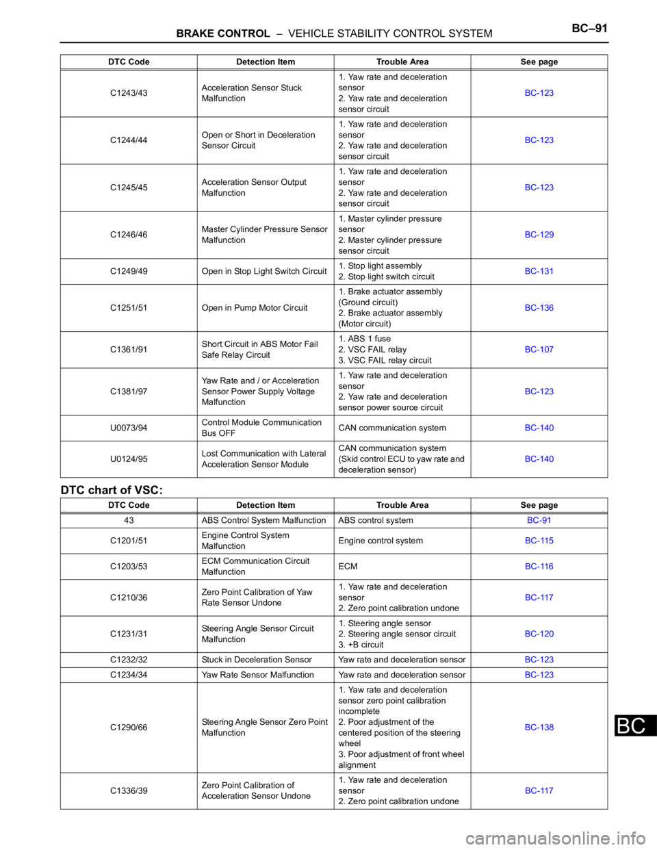
DTC chart of VSC:
C1243/43Acceleration Sensor Stuck
Malfunction1. Yaw rate and deceleration
sensor
2. Yaw rate and deceleration
sensor circuitBC-123
C1244/44Open or Short in Deceleration
Sensor Circuit1. Yaw rate and deceleration
sensor
2. Yaw rate and deceleration
sensor circuitBC-123
C1245/45Acceleration Sensor Output
Malfunction1. Yaw rate and deceleration
sensor
2. Yaw rate and deceleration
sensor circuitBC-123
C1246/46Master Cylinder Pressure Sensor
Malfunction1. Master cylinder pressure
sensor
2. Master cylinder pressure
sensor circuitBC-129
C1249/49 Open in Stop Light Switch Circuit1. Stop light assembly
2. Stop light switch circuitBC-131
C1251/51 Open in Pump Motor Circuit1. Brake actuator assembly
(Ground circuit)
2. Brake actuator assembly
(Motor circuit)BC-136
C1361/91Short Circuit in ABS Motor Fail
Safe Relay Circuit1. ABS 1 fuse
2. VSC FAIL relay
3. VSC FAIL relay circuitBC-107
C1381/97Yaw Rate and / or Acceleration
Sensor Power Supply Voltage
Malfunction1. Yaw rate and deceleration
sensor
2. Yaw rate and deceleration
sensor power source circuitBC-123
U0073/94Control Module Communication
Bus OFFCAN communication systemBC-140
U0124/95Lost Communication with Lateral
Acceleration Sensor ModuleCAN communication system
(Skid control ECU to yaw rate and
deceleration sensor)BC-140
DTC Code Detection Item Trouble Area See page
43 ABS Control System Malfunction ABS control systemBC-91
C1201/51Engine Control System
MalfunctionEngine control systemBC-115
C1203/53ECM Communication Circuit
MalfunctionECMBC-116
C1210/36Zero Point Calibration of Yaw
Rate Sensor Undone1. Yaw rate and deceleration
sensor
2. Zero point calibration undoneBC-117
C1231/31Steering Angle Sensor Circuit
Malfunction1. Steering angle sensor
2. Steering angle sensor circuit
3. +B circuitBC-120
C1232/32 Stuck in Deceleration Sensor Yaw rate and deceleration sensorBC-123
C1234/34 Yaw Rate Sensor Malfunction Yaw rate and deceleration sensorBC-123
C1290/66Steering Angle Sensor Zero Point
Malfunction1. Yaw rate and deceleration
sensor zero point calibration
incomplete
2. Poor adjustment of the
centered position of the steering
wheel
3. Poor adjustment of front wheel
alignmentBC-138
C1336/39Zero Point Calibration of
Acceleration Sensor Undone1. Yaw rate and deceleration
sensor
2. Zero point calibration undoneBC-117 DTC Code Detection Item Trouble Area See page
Page 2474 of 3000

BC–112BRAKE CONTROL – VEHICLE STABILITY CONTROL SYSTEM
BC
OK
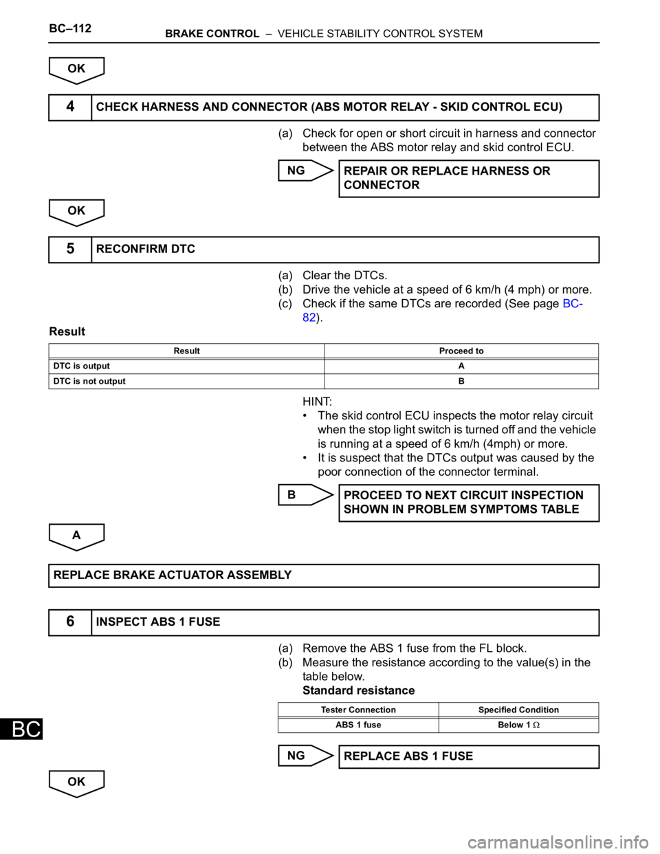
(a) Check for open or short circuit in harness and connector
between the ABS motor relay and skid control ECU.
NG
OK
(a) Clear the DTCs.
(b) Drive the vehicle at a speed of 6 km/h (4 mph) or more.
(c) Check if the same DTCs are recorded (See page BC-
82).
Result
HINT:
• The skid control ECU inspects the motor relay circuit
when the stop light switch is turned off and the vehicle
is running at a speed of 6 km/h (4mph) or more.
• It is suspect that the DTCs output was caused by the
poor connection of the connector terminal.
B
A
(a) Remove the ABS 1 fuse from the FL block.
(b) Measure the resistance according to the value(s) in the
table below.
Standard resistance
NG
OK
4CHECK HARNESS AND CONNECTOR (ABS MOTOR RELAY - SKID CONTROL ECU)
REPAIR OR REPLACE HARNESS OR
CONNECTOR
5RECONFIRM DTC
Result Proceed to
DTC is outputA
DTC is not outputB
PROCEED TO NEXT CIRCUIT INSPECTION
SHOWN IN PROBLEM SYMPTOMS TABLE
REPLACE BRAKE ACTUATOR ASSEMBLY
6INSPECT ABS 1 FUSE
Tester Connection Specified Condition
ABS 1 fuse Below 1
REPLACE ABS 1 FUSE
Page 2493 of 3000

BRAKE CONTROL – VEHICLE STABILITY CONTROL SYSTEMBC–131
BC
DESCRIPTION
Master cylinder pressure sensor is connected to the skid control ECU in the actuator.
INSPECTION PROCEDURE
(a) Connect the intelligent tester to the DLC3.
(b) Start the engine.
(c) Select the DATA LIST mode on the intelligent tester.
ABS / VSC:
(d) Check that the brake fluid pressure value of the master
cylinder pressure sensor indicated on the intelligent
tester, changes when the brake pedal is depressed.
OK:
Brake fluid pressure value should change.
NOTICE:
When replacing the brake actuator assembly,
perform zero point calibration (See page BC-70).
NG
OK
DTC C1246/46 Master Cylinder Pressure Sensor Malfunction
DTC Code DTC Detection Condition Trouble Area
C1246/46When any of the following is detected:
1. When the vehicle speed is 7 km/h (4 mph) or more
and PMC terminal voltage of skid control ECU
exceeds 0.86 V, the condition that the voltage does
not change by 0.005 V or more continues for 30
sec.
2. Noise in terminal PMC of skid control ECU occurs 7
times or more within 5 sec.
3. When the stop light switch is off, the condition that
PMC terminal voltage of skid control ECU is 0.86 V
or more, or less than 0.3 V continues for 5 sec. or
more.
4. When IG1 terminal voltage is between 9.5 and 17.2
V, the condition that the VCM terminal voltage of
skid control ECU is out of the range from 4.4 to 5.6
V continues for 1.2 sec. or more.
5. When VCM terminal voltage of skid control ECU is
between 4.4 and 5.6 V, the condition that the PMC
terminal voltage of skid control ECU is out of the
range from 0.14 to 4.85 V continues for 1.2 sec. or
more.• Master cylinder pressure sensor
• Master cylinder pressure sensor circuit
1READ VALUE ON INTELLIGENT TESTER (MASTER CYLINDER PRESSURE SENSOR)
Tester Display Measurement Item/Range Normal Condition
MAS CYL PRS 1Master cylinder pressure sensor 1 reading /
min.: 0 V, max.: 5 VWhen brake pedal is released : 0.3 to 0.9 V
Go to step 2
REPLACE BRAKE ACTUATOR ASSEMBLY
Page 2494 of 3000
BC–132BRAKE CONTROL – VEHICLE STABILITY CONTROL SYSTEM
BC
(a) Disconnect the skid control ECU connector.
(b) Measure the voltage according to the value(s) in the
table below.
Standard voltage
NOTICE:
When replacing the brake actuator assembly,
perform zero point calibration (See page BC-70).
NG
OK
2INSPECT SKID CONTROL ECU (STP1 TERMINAL)
G024767E58
Tester Connection Condition Specified Condition
S3-27 (STP1) - Body
groundBrake pedal depressed 8 to 14 V
S3-27 (STP1) - Body
groundBrake pedal depressed Below 1 V
REPAIR OR REPLACE STOP LIGHT SWITCH
CIRCUIT
REPLACE BRAKE ACTUATOR ASSEMBLY
Page 2495 of 3000
BRAKE CONTROL – VEHICLE STABILITY CONTROL SYSTEMBC–133
BC
DESCRIPTION
WIRING DIAGRAM
DTC C1249/49 Open in Stop Light Switch Circuit
DTC Code DTC Detection Condition Trouble Area
C1249/49When IG1 terminal voltage is 9.5 to 18.5 V, an open
circuit of the stop light switch continues for 0.3 sec. or
more.• Stop light assembly
• Stop light switch circuit
C160967E01
Page 2497 of 3000

BRAKE CONTROL – VEHICLE STABILITY CONTROL SYSTEMBC–135
BC
INSPECTION PROCEDURE
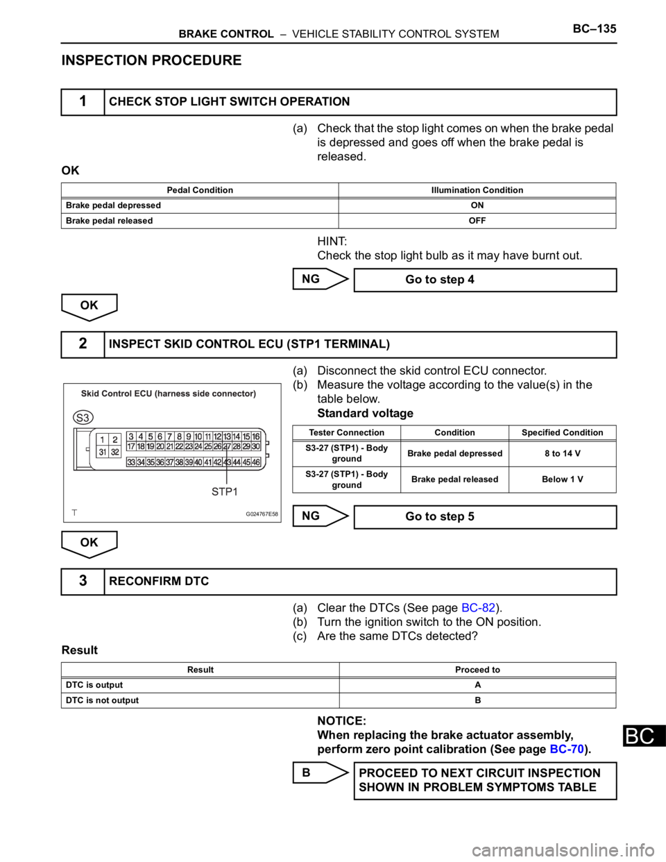
(a) Check that the stop light comes on when the brake pedal
is depressed and goes off when the brake pedal is
released.
OK
HINT:
Check the stop light bulb as it may have burnt out.
NG
OK
(a) Disconnect the skid control ECU connector.
(b) Measure the voltage according to the value(s) in the
table below.
Standard voltage
NG
OK
(a) Clear the DTCs (See page BC-82).
(b) Turn the ignition switch to the ON position.
(c) Are the same DTCs detected?
Result
NOTICE:
When replacing the brake actuator assembly,
perform zero point calibration (See page BC-70).
B
1CHECK STOP LIGHT SWITCH OPERATION
Pedal Condition Illumination Condition
Brake pedal depressedON
Brake pedal releasedOFF
Go to step 4
2INSPECT SKID CONTROL ECU (STP1 TERMINAL)
G024767E58
Tester Connection Condition Specified Condition
S3-27 (STP1) - Body
groundBrake pedal depressed 8 to 14 V
S3-27 (STP1) - Body
groundBrake pedal released Below 1 V
Go to step 5
3RECONFIRM DTC
Result Proceed to
DTC is outputA
DTC is not outputB
PROCEED TO NEXT CIRCUIT INSPECTION
SHOWN IN PROBLEM SYMPTOMS TABLE
Page 2498 of 3000
BC–136BRAKE CONTROL – VEHICLE STABILITY CONTROL SYSTEM
BC
A
(a) Disconnect the stop light switch assembly connector.
(b) Measure the resistance according to the value(s) in the
table below.
Standard resistance
NG
OK
(a) Disconnect the stop light switch connector and skid
control ECU connector.
(b) Measure the resistance according to the value(s) in the
table below.
Standard resistance
NOTICE:
When replacing the brake actuator assembly,
perform zero point calibration (See page BC-70).
NG REPLACE BRAKE ACTUATOR ASSEMBLY
4INSPECT STOP LIGHT SWITCH
C146625E04
Tester connection Switch condition Specified condition
1 - 2 Switch pin free Below 1
1 - 2 Switch pin pushed in 10 k or higher
REPLACE STOP LIGHT SWITCH
5CHECK HARNESS AND CONNECTOR (STOP LIGHT SWITCH - SKID CONTROL ECU)
G026188E08
Tester Connection Specified Condition
S3-27 (STP1) - S12-1 (STP) Below 1
REPAIR OR REPLACE HARNESS OR
CONNECTOR
Page 2542 of 3000

BC–18BRAKE CONTROL – ANTI-LOCK BRAKE SYSTEM
BC
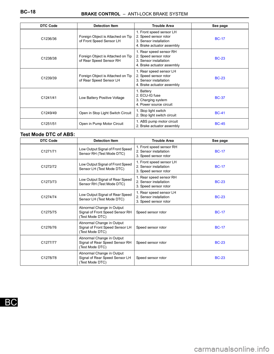
Test Mode DTC of ABS:
C1236/36Foreign Object is Attached on Tip
of Front Speed Sensor LH1. Front speed sensor LH
2. Speed sensor rotor
3. Sensor installation
4. Brake actuator assemblyBC-17
C1238/38Foreign Object is Attached on Tip
of Rear Speed Sensor RH1. Rear speed sensor RH
2. Speed sensor rotor
3. Sensor installation
4. Brake actuator assemblyBC-23
C1239/39Foreign Object is Attached on Tip
of Rear Speed Sensor LH1. Rear speed sensor LH
2. Speed sensor rotor
3. Sensor installation
4. Brake actuator assemblyBC-23
C1241/41 Low Battery Positive Voltage1. Battery
2. ECU-IG fuse
3. Charging system
4. Power source circuitBC-37
C1249/49 Open in Stop Light Switch Circuit1. Stop light switch
2. Stop light switch circuitBC-41
C1251/51 Open in Pump Motor Circuit1. ABS pump motor circuit
2. Brake actuator assemblyBC-45
DTC Code Detection Item Trouble Area See page
C1271/71Low Output Signal of Front Speed
Sensor RH (Test Mode DTC)1. Front speed sensor RH
2. Sensor installation
3. Speed sensor rotorBC-17
C1272/72Low Output Signal of Front Speed
Sensor LH (Test Mode DTC)1. Front speed sensor LH
2. Sensor installation
3. Speed sensor rotorBC-17
C1273/73Low Output Signal of Rear Speed
Sensor RH (Test Mode DTC)1. Rear speed sensor RH
2. Sensor installation
3. Speed sensor rotorBC-23
C1274/74Low Output Signal of Rear Speed
Sensor LH (Test Mode DTC)1. Rear speed sensor LH
2. Sensor installation
3. Speed sensor rotorBC-23
C1275/75Abnormal Change in Output
Signal of Front Speed Sensor RH
(Test Mode DTC)Speed sensor rotorBC-17
C1276/76Abnormal Change in Output
Signal of Front Speed Sensor LH
(Test Mode DTC)Speed sensor rotorBC-17
C1277/77Abnormal Change in Output
Signal of Rear Speed Sensor RH
(Test Mode DTC)Speed sensor rotorBC-23
C1278/78Abnormal Change in Output
Signal of Rear Speed Sensor LH
(Test Mode DTC)Speed sensor rotorBC-23 DTC Code Detection Item Trouble Area See page