Page 2568 of 3000
BC–32BRAKE CONTROL – ANTI-LOCK BRAKE SYSTEM
BC
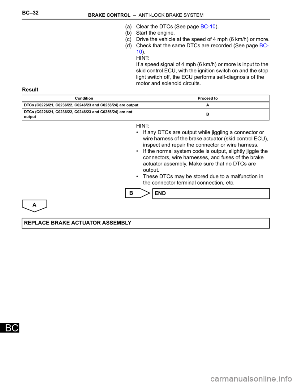
(a) Clear the DTCs (See page BC-10).
(b) Start the engine.
(c) Drive the vehicle at the speed of 4 mph (6 km/h) or more.
(d) Check that the same DTCs are recorded (See page BC-
10).
HINT:
If a speed signal of 4 mph (6 km/h) or more is input to the
skid control ECU, with the ignition switch on and the stop
light switch off, the ECU performs self-diagnosis of the
motor and solenoid circuits.
Result
HINT:
• If any DTCs are output while jiggling a connector or
wire harness of the brake actuator (skid control ECU),
inspect and repair the connector or wire harness.
• If the normal system code is output, slightly jiggle the
connectors, wire harnesses, and fuses of the brake
actuator assembly. Make sure that no DTCs are
output.
• These DTCs may be stored due to a malfunction in
the connector terminal connection, etc.
B
A
Condition Proceed to
DTCs (C0226/21, C0236/22, C0246/23 and C0256/24) are output A
DTCs (C0226/21, C0236/22, C0246/23 and C0256/24) are not
outputB
END
REPLACE BRAKE ACTUATOR ASSEMBLY
Page 2573 of 3000
BRAKE CONTROL – ANTI-LOCK BRAKE SYSTEMBC–35
BC
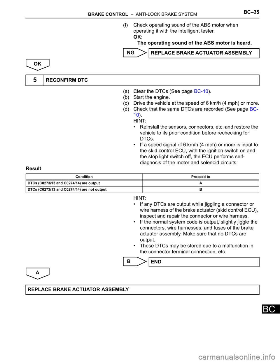
(f) Check operating sound of the ABS motor when
operating it with the intelligent tester.
OK:
The operating sound of the ABS motor is heard.
NG
OK
(a) Clear the DTCs (See page BC-10).
(b) Start the engine.
(c) Drive the vehicle at the speed of 6 km/h (4 mph) or more.
(d) Check that the same DTCs are recorded (See page BC-
10).
HINT:
• Reinstall the sensors, connectors, etc. and restore the
vehicle to its prior condition before rechecking for
DTCs.
• If a speed signal of 6 km/h (4 mph) or more is input to
the skid control ECU, with the ignition switch on and
the stop light switch off, the ECU performs self-
diagnosis of the motor and solenoid circuits.
Result
HINT:
• If any DTCs are output while jiggling a connector or
wire harness of the brake actuator (skid control ECU),
inspect and repair the connector or wire harness.
• If the normal system code is output, slightly jiggle the
connectors, wire harnesses, and fuses of the brake
actuator assembly. Make sure that no DTCs are
output.
• These DTCs may be stored due to a malfunction in
the connector terminal connection, etc.
B
AREPLACE BRAKE ACTUATOR ASSEMBLY
5RECONFIRM DTC
Condition Proceed to
DTCs (C0273/13 and C0274/14) are output A
DTCs (C0273/13 and C0274/14) are not output B
END
REPLACE BRAKE ACTUATOR ASSEMBLY
Page 2588 of 3000

BRAKE – BRAKE PEDALBR–13
BR
REASSEMBLY
1. INSTALL BRAKE PEDAL PAD
(a) Install the brake pedal pad to the brake pedal sub-
assembly.
2. INSTALL PUSH ROD PIN
(a) Apply lithium soap base glycol grease to inside
surface of 2 new push rod bushes.
(b) Install the 2 new push rod bushes.
(c) Install the 2 push rod pins with the 2 plate to the
brake pedal.
(d) Using needle-nose pliers, install the 2 new E-rings
to the 2 push rod pins.
NOTICE:
Install the E-ring securely to the grooves of the
push rod pin.
3. INSTALL BRAKE PEDAL BUSH
(a) Apply lithium soap base glycol grease to inside
surface of 4 new brake pedal bushes.
(b) Install the 4 brake pedal bushes to the brake pedal.
4. INSTALL BRAKE PEDAL SHAFT COLLAR
(a) Apply the lithium soap base glycol grease to inside
surface of 2 brake pedal shaft collars.
(b) Install the 2 brake pedal shaft collars to the brake
pedal.
5. INSTALL BRAKE PEDAL
(a) Install the 2 brake pedal shafts, 2 nuts, brake pedal
and brake pedal bracket No. 3 to the brake pedal
support sub-assembly.
6. INSTALL STOP LIGHT SWITCH CUSHION
(a) Install the stop light switch cushion to the brake
pedal sub-assembly.
7. INSTALL STOP LIGHT SWITCH ASSEMBLY
(a) Install the stop light switch mounting adjuster to the
brake pedal support sub-assembly.
(b) Install the stop light switch assembly until the body
hits the cushion.
(c) Make a quarter turn clockwise to install the stop light
switch assembly.
NOTICE:
The turning torque for installing the stop light
switch assembly.
Torque: 1.5 N*m (15 kgf*cm, 13 in.*lbf) or less
HINT:
Due to the inverse screw structure, if the stop light
switch assembly is turned clockwise, the stop light
switch assembly moves in the direction to be pulled
out.
Page 2589 of 3000

BR–14BRAKE – BRAKE PEDAL
BR
INSTALLATION
1. INSTALL BRAKE PEDAL SUPPORT ASSEMBLY
(a) Install the brake pedal support sub-assembly with
the 4 nuts.
Torque: 16 N*m (160 kgf*cm, 12 ft.*lbf)
(b) Install the clip and clevis pin to the brake pedal
lever.
(c) Using needle-nose pliers, install the tension spring.
(d) Install the 2 bolts to the brake pedal bracket No. 3.
Torque: 19 N*m (194 kgf*cm, 14 ft.*lbf)
(e) Install the stop light switch harness clamp to the
brake pedal support sub-assembly.
(f) Connect the stop light switch connector.
2. FULLY TIGHTEN BRAKE PEDAL SHAFT
(a) Fully tighten the 2 brake pedal shafts.
Torque: 34 N*m (350 kgf*cm, 25 ft.*lbf)
3. INSTALL INSTRUMENT PANEL SAFETY PAD INSERT
SUB-ASSEMBLY NO. 1
(a) Install the instrument panel safety pad insert sub-
assembly No. 1 with the 4 bolts.
4. INSTALL INSTRUMENT PANEL FINISH PANEL SUB-
ASSEMBLY LOWER LH
(a) Install the instrument panel finish panel sub-
assembly lower LH with the 2 bolts.
5. INSTALL COWL SIDE TRIM BOARD LH
6. INSTALL FRONT DOOR SCUFF PLATE LH
7. INSPECT BRAKE PEDAL HEIGHT (See page BR-9)
8. CHECK PEDAL FREE PLAY (See page BR-10)
9. CHECK PEDAL RESERVE DISTANCE (See page BR-
10)
G024262
G024263
F045360E01
Page 2604 of 3000
BRAKE – BRAKE PEDALBR–9
BR
ON-VEHICLE INSPECTION
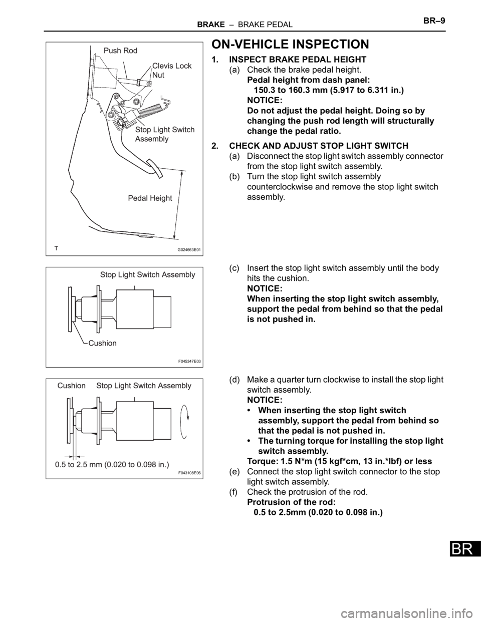
1. INSPECT BRAKE PEDAL HEIGHT
(a) Check the brake pedal height.
Pedal height from dash panel:
150.3 to 160.3 mm (5.917 to 6.311 in.)
NOTICE:
Do not adjust the pedal height. Doing so by
changing the push rod length will structurally
change the pedal ratio.
2. CHECK AND ADJUST STOP LIGHT SWITCH
(a) Disconnect the stop light switch assembly connector
from the stop light switch assembly.
(b) Turn the stop light switch assembly
counterclockwise and remove the stop light switch
assembly.
(c) Insert the stop light switch assembly until the body
hits the cushion.
NOTICE:
When inserting the stop light switch assembly,
support the pedal from behind so that the pedal
is not pushed in.
(d) Make a quarter turn clockwise to install the stop light
switch assembly.
NOTICE:
• When inserting the stop light switch
assembly, support the pedal from behind so
that the pedal is not pushed in.
• The turning torque for installing the stop light
switch assembly.
Torque: 1.5 N*m (15 kgf*cm, 13 in.*lbf) or less
(e) Connect the stop light switch connector to the stop
light switch assembly.
(f) Check the protrusion of the rod.
Protrusion of the rod:
0.5 to 2.5mm (0.020 to 0.098 in.)
G024663E01
F045347E03
F043108E06
Page 2606 of 3000

BRAKE – BRAKE PEDALBR–13
BR
REASSEMBLY
1. INSTALL BRAKE PEDAL PAD
(a) Install the brake pedal pad to the brake pedal sub-
assembly.
2. INSTALL PUSH ROD PIN
(a) Apply lithium soap base glycol grease to inside
surface of 2 new push rod bushes.
(b) Install the 2 new push rod bushes.
(c) Install the 2 push rod pins with the 2 plate to the
brake pedal.
(d) Using needle-nose pliers, install the 2 new E-rings
to the 2 push rod pins.
NOTICE:
Install the E-ring securely to the grooves of the
push rod pin.
3. INSTALL BRAKE PEDAL BUSH
(a) Apply lithium soap base glycol grease to inside
surface of 4 new brake pedal bushes.
(b) Install the 4 brake pedal bushes to the brake pedal.
4. INSTALL BRAKE PEDAL SHAFT COLLAR
(a) Apply the lithium soap base glycol grease to inside
surface of 2 brake pedal shaft collars.
(b) Install the 2 brake pedal shaft collars to the brake
pedal.
5. INSTALL BRAKE PEDAL
(a) Install the 2 brake pedal shafts, 2 nuts, brake pedal
and brake pedal bracket No. 3 to the brake pedal
support sub-assembly.
6. INSTALL STOP LIGHT SWITCH CUSHION
(a) Install the stop light switch cushion to the brake
pedal sub-assembly.
7. INSTALL STOP LIGHT SWITCH ASSEMBLY
(a) Install the stop light switch mounting adjuster to the
brake pedal support sub-assembly.
(b) Install the stop light switch assembly until the body
hits the cushion.
(c) Make a quarter turn clockwise to install the stop light
switch assembly.
NOTICE:
The turning torque for installing the stop light
switch assembly.
Torque: 1.5 N*m (15 kgf*cm, 13 in.*lbf) or less
HINT:
Due to the inverse screw structure, if the stop light
switch assembly is turned clockwise, the stop light
switch assembly moves in the direction to be pulled
out.
Page 2607 of 3000
BR–14BRAKE – BRAKE PEDAL
BR
INSTALLATION
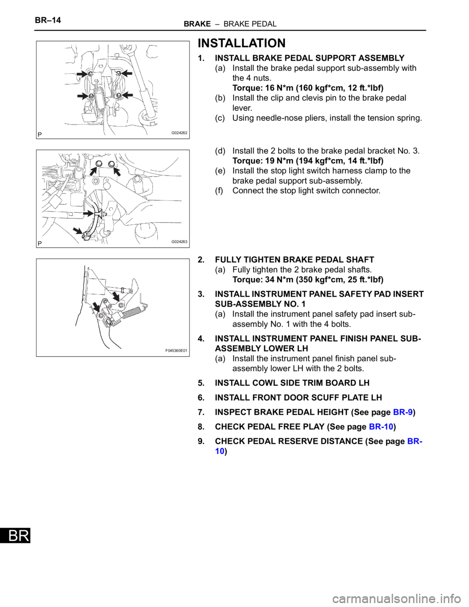
1. INSTALL BRAKE PEDAL SUPPORT ASSEMBLY
(a) Install the brake pedal support sub-assembly with
the 4 nuts.
Torque: 16 N*m (160 kgf*cm, 12 ft.*lbf)
(b) Install the clip and clevis pin to the brake pedal
lever.
(c) Using needle-nose pliers, install the tension spring.
(d) Install the 2 bolts to the brake pedal bracket No. 3.
Torque: 19 N*m (194 kgf*cm, 14 ft.*lbf)
(e) Install the stop light switch harness clamp to the
brake pedal support sub-assembly.
(f) Connect the stop light switch connector.
2. FULLY TIGHTEN BRAKE PEDAL SHAFT
(a) Fully tighten the 2 brake pedal shafts.
Torque: 34 N*m (350 kgf*cm, 25 ft.*lbf)
3. INSTALL INSTRUMENT PANEL SAFETY PAD INSERT
SUB-ASSEMBLY NO. 1
(a) Install the instrument panel safety pad insert sub-
assembly No. 1 with the 4 bolts.
4. INSTALL INSTRUMENT PANEL FINISH PANEL SUB-
ASSEMBLY LOWER LH
(a) Install the instrument panel finish panel sub-
assembly lower LH with the 2 bolts.
5. INSTALL COWL SIDE TRIM BOARD LH
6. INSTALL FRONT DOOR SCUFF PLATE LH
7. INSPECT BRAKE PEDAL HEIGHT (See page BR-9)
8. CHECK PEDAL FREE PLAY (See page BR-10)
9. CHECK PEDAL RESERVE DISTANCE (See page BR-
10)
G024262
G024263
F045360E01
Page 2672 of 3000
SR–8STEERING COLUMN – STEERING COLUMN ASSEMBLY
SR
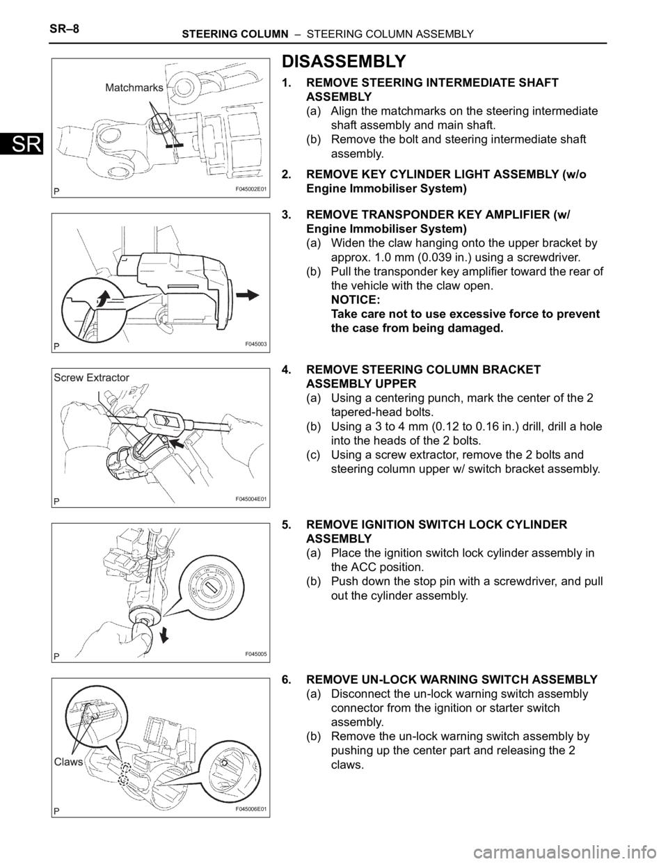
DISASSEMBLY
1. REMOVE STEERING INTERMEDIATE SHAFT
ASSEMBLY
(a) Align the matchmarks on the steering intermediate
shaft assembly and main shaft.
(b) Remove the bolt and steering intermediate shaft
assembly.
2. REMOVE KEY CYLINDER LIGHT ASSEMBLY (w/o
Engine Immobiliser System)
3. REMOVE TRANSPONDER KEY AMPLIFIER (w/
Engine Immobiliser System)
(a) Widen the claw hanging onto the upper bracket by
approx. 1.0 mm (0.039 in.) using a screwdriver.
(b) Pull the transponder key amplifier toward the rear of
the vehicle with the claw open.
NOTICE:
Take care not to use excessive force to prevent
the case from being damaged.
4. REMOVE STEERING COLUMN BRACKET
ASSEMBLY UPPER
(a) Using a centering punch, mark the center of the 2
tapered-head bolts.
(b) Using a 3 to 4 mm (0.12 to 0.16 in.) drill, drill a hole
into the heads of the 2 bolts.
(c) Using a screw extractor, remove the 2 bolts and
steering column upper w/ switch bracket assembly.
5. REMOVE IGNITION SWITCH LOCK CYLINDER
ASSEMBLY
(a) Place the ignition switch lock cylinder assembly in
the ACC position.
(b) Push down the stop pin with a screwdriver, and pull
out the cylinder assembly.
6. REMOVE UN-LOCK WARNING SWITCH ASSEMBLY
(a) Disconnect the un-lock warning switch assembly
connector from the ignition or starter switch
assembly.
(b) Remove the un-lock warning switch assembly by
pushing up the center part and releasing the 2
claws.
F045002E01
F045003
F045004E01
F045005
F045006E01