2007 TOYOTA SIENNA Zero point
[x] Cancel search: Zero pointPage 2186 of 3000
SP–4SUSPENSION – FRONT WHEEL ALIGNMENT
SP
FRONT WHEEL ALIGNMENT
ADJUSTMENT
NOTICE:
For vehicles equipped with VSC, if wheel alignment has
been adjusted, and if suspension or underbody
components have been removed/installed or replaced, be
sure to perform the following initialization procedure in
order for the system to function normally:
1. Disconnect the negative battery terminal for more
than 2 seconds.
2. Reconnect the negative battery terminal.
3. Perform zero point calibration of the yaw rate and
acceleration sensor and test mode inspection.
HINT:
(See page BC-70)
1. INSPECT TIRE
HINT:
(See page TW-2)
2. MEASURE VEHICLE HEIGHT
(a) Bounce the vehicle at the corners up and down to
stabilize the suspension and inspect the vehicle
height.
Vehicle height:
FF
4WD
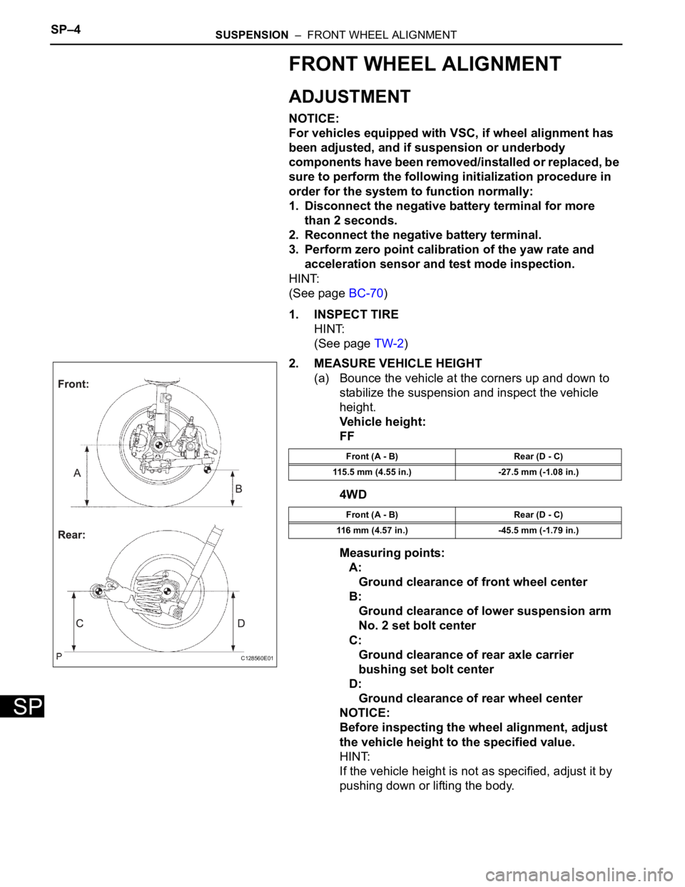
Measuring points:
A:
Ground clearance of front wheel center
B:
Ground clearance of lower suspension arm
No. 2 set bolt center
C:
Ground clearance of rear axle carrier
bushing set bolt center
D:
Ground clearance of rear wheel center
NOTICE:
Before inspecting the wheel alignment, adjust
the vehicle height to the specified value.
HINT:
If the vehicle height is not as specified, adjust it by
pushing down or lifting the body.
C128560E01
Front (A - B) Rear (D - C)
115.5 mm (4.55 in.) -27.5 mm (-1.08 in.)
Front (A - B) Rear (D - C)
116 mm (4.57 in.) -45.5 mm (-1.79 in.)
Page 2192 of 3000
SUSPENSION – REAR WHEEL ALIGNMENTSP–9
SP
REAR WHEEL ALIGNMENT
ADJUSTMENT
NOTICE:
For vehicles equipped with VSC, if wheel alignment has
been adjusted, and if suspension or underbody
components have been removed/installed or replaced, be
sure to perform the following initialization procedure in
order for the system to function normally:
1. Disconnect the negative battery terminal for more
than 2 seconds.
2. Reconnect the negative battery terminal.
3. Perform zero point calibration of the yaw rate and
acceleration sensor and test mode inspection.
HINT:
(See page BC-70)
1. INSPECT TIRE
HINT:
(See page TW-2)
2. MEASURE VEHICLE HEIGHT
NOTICE:
Before inspecting the wheel alignment, adjust the
vehicle height to the specified valve.
3. INSPECT TOE-IN
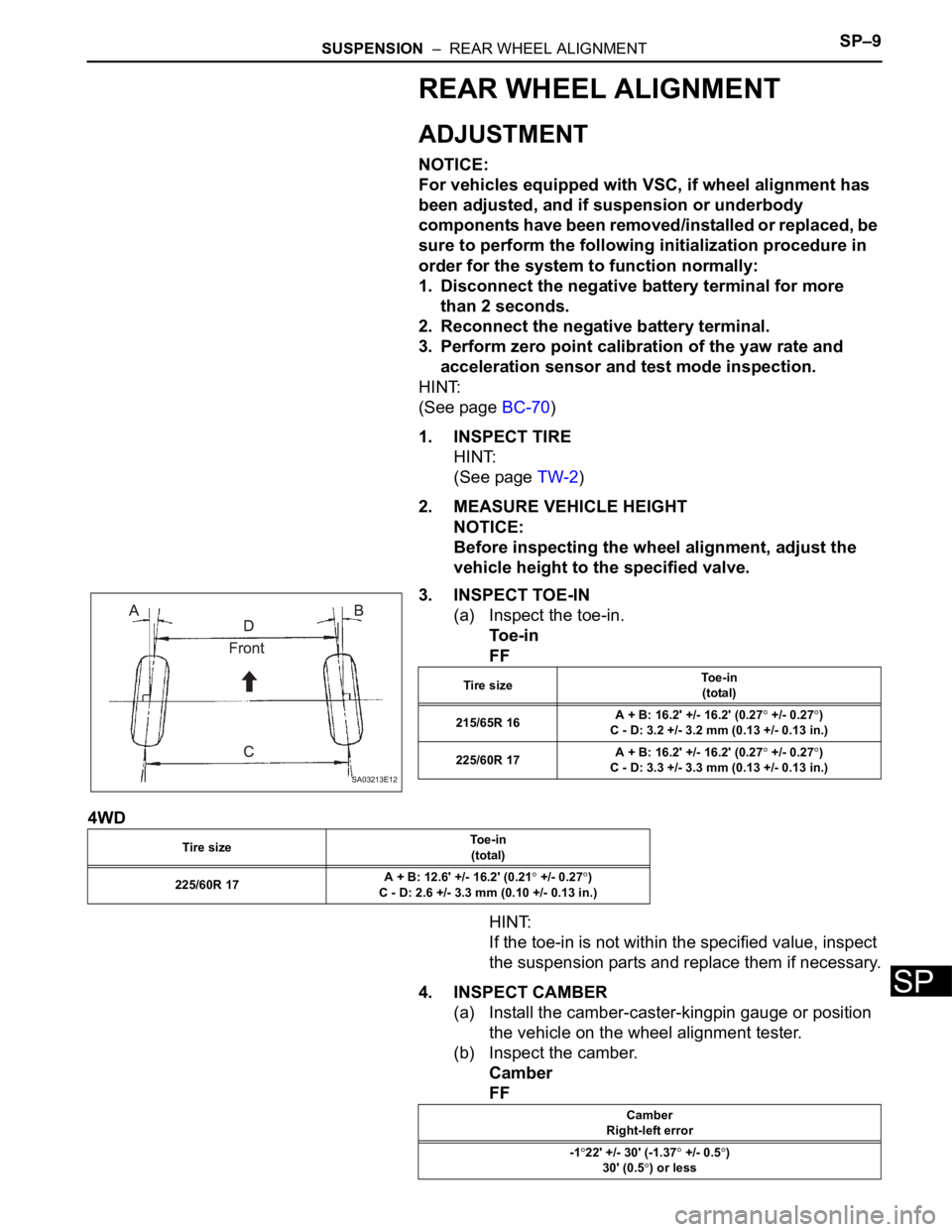
(a) Inspect the toe-in.
To e - i n
FF
4WD
HINT:
If the toe-in is not within the specified value, inspect
the suspension parts and replace them if necessary.
4. INSPECT CAMBER
(a) Install the camber-caster-kingpin gauge or position
the vehicle on the wheel alignment tester.
(b) Inspect the camber.
Camber
FF
SA03213E12
Tire sizeTo e - i n
(total)
215/65R 16A + B: 16.2' +/- 16.2' (0.27
+/- 0.27)
C - D: 3.2 +/- 3.2 mm (0.13 +/- 0.13 in.)
225/60R 17A + B: 16.2' +/- 16.2' (0.27
+/- 0.27)
C - D: 3.3 +/- 3.3 mm (0.13 +/- 0.13 in.)
Tire sizeTo e - i n
(total)
225/60R 17A + B: 12.6' +/- 16.2' (0.21
+/- 0.27)
C - D: 2.6 +/- 3.3 mm (0.10 +/- 0.13 in.)
Camber
Right-left error
-1
22' +/- 30' (-1.37 +/- 0.5)
30' (0.5
) or less
Page 2434 of 3000
BC–70BRAKE CONTROL – VEHICLE STABILITY CONTROL SYSTEM
BC
CALIBRATION
1. CLEAR ZERO POINT CALIBRATION (WHEN USING
INTELLIGENT TESTER):
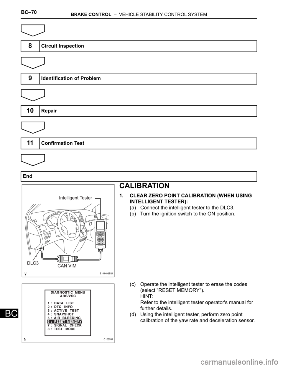
(a) Connect the intelligent tester to the DLC3.
(b) Turn the ignition switch to the ON position.
(c) Operate the intelligent tester to erase the codes
(select "RESET MEMORY").
HINT:
Refer to the intelligent tester operator's manual for
further details.
(d) Using the intelligent tester, perform zero point
calibration of the yaw rate and deceleration sensor.
8Circuit Inspection
9Identification of Problem
10Repair
11Confirmation Test
End
E144486E01
C106531
Page 2435 of 3000
BRAKE CONTROL – VEHICLE STABILITY CONTROL SYSTEMBC–71
BC
2. PERFORM ZERO POINT CALIBRATION OF YAW
RATE AND DECELERATION SENSOR (WHEN USING
INTELLIGENT TESTER):
NOTICE:
• While obtaining the zero point, do not vibrate the
vehicle by tilting, moving or shaking it and keep it
in a stationary condition. (Do not turn the ignition
switch to the ON position.)
• Be sure to do this on a level surface (with an
inclination of less than 1 %).
(a) Procedures for test mode.
(1) Check that the steering wheel is in the straight-
ahead position and move the shift lever to the P
position and apply the parking brake.
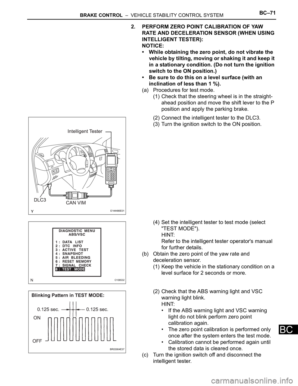
(2) Connect the intelligent tester to the DLC3.
(3) Turn the ignition switch to the ON position.
(4) Set the intelligent tester to test mode (select
"TEST MODE").
HINT:
Refer to the intelligent tester operator's manual
for further details.
(b) Obtain the zero point of the yaw rate and
deceleration sensor.
(1) Keep the vehicle in the stationary condition on a
level surface for 2 seconds or more.
(2) Check that the ABS warning light and VSC
warning light blink.
HINT:
• If the ABS warning light and VSC warning
light do not blink perform zero point
calibration again.
• The zero point calibration is performed only
once after the system enters the test mode.
• Calibration cannot be performed again until
the stored data is cleared once.
(c) Turn the ignition switch off and disconnect the
intelligent tester.
E144486E01
C106532
BR03904E37
Page 2436 of 3000
BC–72BRAKE CONTROL – VEHICLE STABILITY CONTROL SYSTEM
BC
3. PERFORM ZERO POINT CALIBRATION OF YAW
RATE AND DECELERATION SENSOR (WHEN USING
SST CHECK WIRE):
NOTICE:
• While obtaining the zero point, do not vibrate the
vehicle by tilting, moving or shaking it and keep it
in a stationary condition. (Do not turn the ignition
switch to the ON position.)
• Be sure to do this on a level surface (with an
inclination of less than 1 %).
(a) Clear the zero point calibration.
(1) Turn the ignition switch to the ON position.
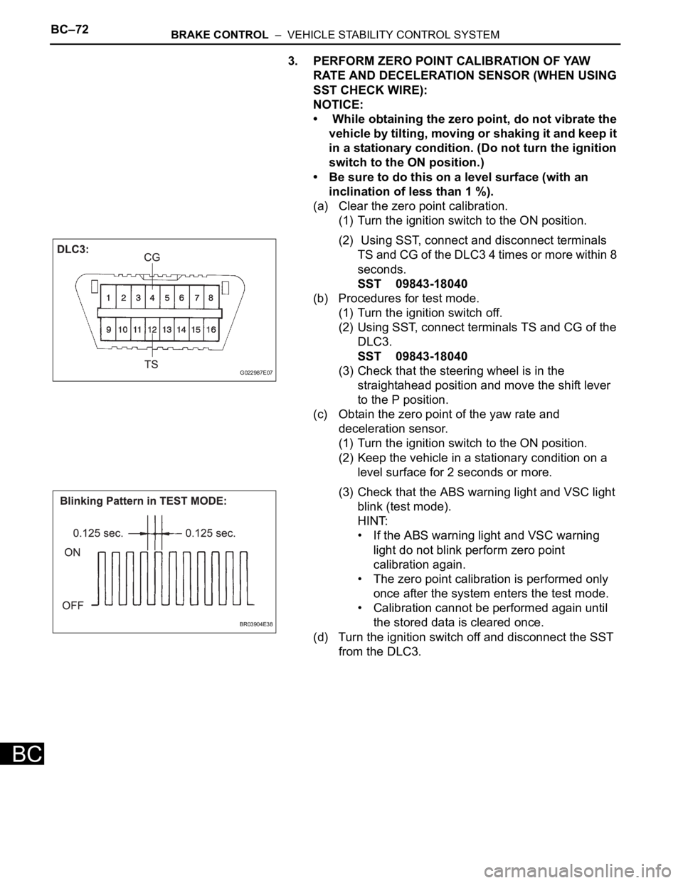
(2) Using SST, connect and disconnect terminals
TS and CG of the DLC3 4 times or more within 8
seconds.
SST 09843-18040
(b) Procedures for test mode.
(1) Turn the ignition switch off.
(2) Using SST, connect terminals TS and CG of the
DLC3.
SST 09843-18040
(3) Check that the steering wheel is in the
straightahead position and move the shift lever
to the P position.
(c) Obtain the zero point of the yaw rate and
deceleration sensor.
(1) Turn the ignition switch to the ON position.
(2) Keep the vehicle in a stationary condition on a
level surface for 2 seconds or more.
(3) Check that the ABS warning light and VSC light
blink (test mode).
HINT:
• If the ABS warning light and VSC warning
light do not blink perform zero point
calibration again.
• The zero point calibration is performed only
once after the system enters the test mode.
• Calibration cannot be performed again until
the stored data is cleared once.
(d) Turn the ignition switch off and disconnect the SST
from the DLC3.
G022987E07
BR03904E38
Page 2437 of 3000
BRAKE CONTROL – VEHICLE STABILITY CONTROL SYSTEMBC–73
BC
TEST MODE PROCEDURE
1. WARNING LIGHT AND INDICATOR LIGHT BULB
CHECK
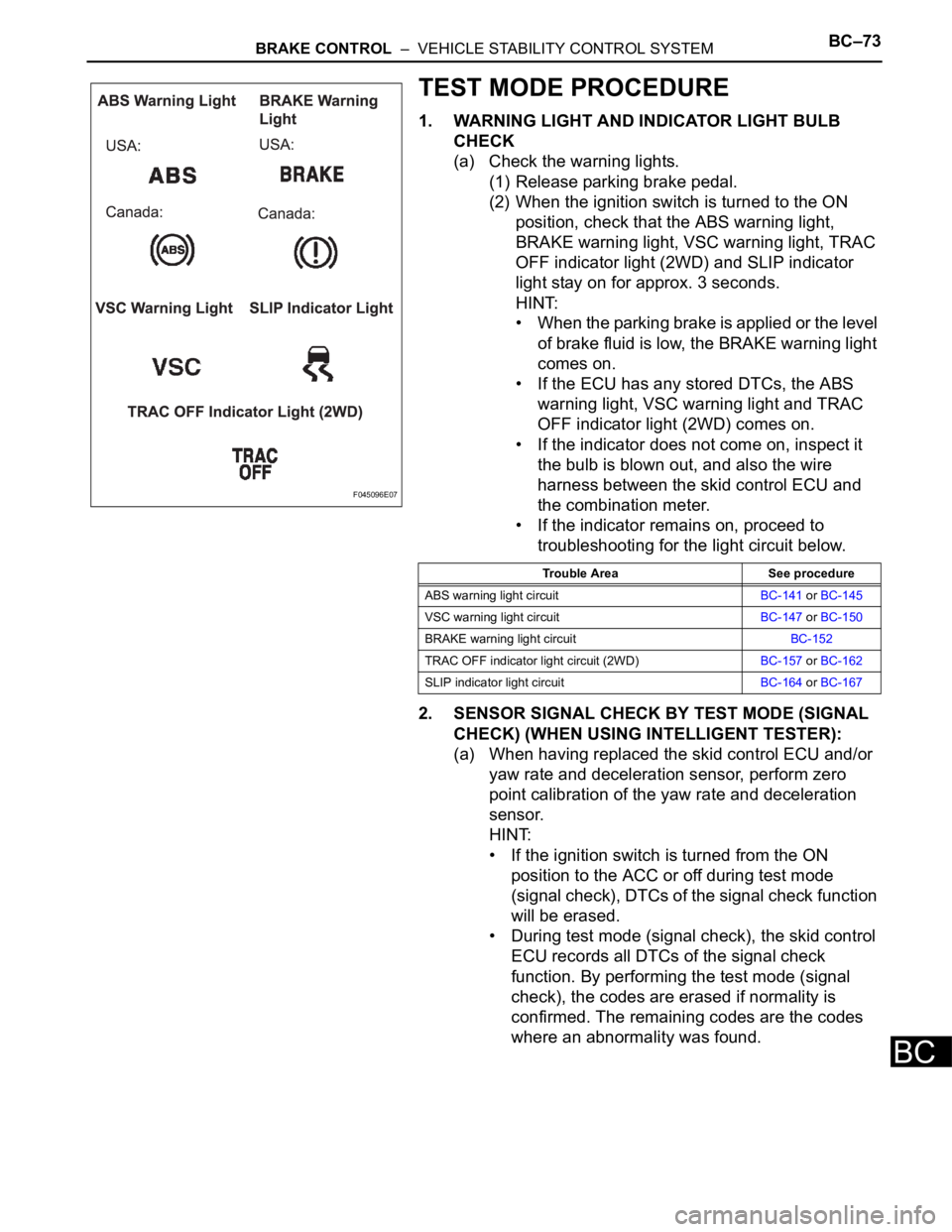
(a) Check the warning lights.
(1) Release parking brake pedal.
(2) When the ignition switch is turned to the ON
position, check that the ABS warning light,
BRAKE warning light, VSC warning light, TRAC
OFF indicator light (2WD) and SLIP indicator
light stay on for approx. 3 seconds.
HINT:
• When the parking brake is applied or the level
of brake fluid is low, the BRAKE warning light
comes on.
• If the ECU has any stored DTCs, the ABS
warning light, VSC warning light and TRAC
OFF indicator light (2WD) comes on.
• If the indicator does not come on, inspect it
the bulb is blown out, and also the wire
harness between the skid control ECU and
the combination meter.
• If the indicator remains on, proceed to
troubleshooting for the light circuit below.
2. SENSOR SIGNAL CHECK BY TEST MODE (SIGNAL
CHECK) (WHEN USING INTELLIGENT TESTER):
(a) When having replaced the skid control ECU and/or
yaw rate and deceleration sensor, perform zero
point calibration of the yaw rate and deceleration
sensor.
HINT:
• If the ignition switch is turned from the ON
position to the ACC or off during test mode
(signal check), DTCs of the signal check function
will be erased.
• During test mode (signal check), the skid control
ECU records all DTCs of the signal check
function. By performing the test mode (signal
check), the codes are erased if normality is
confirmed. The remaining codes are the codes
where an abnormality was found.
F045096E07
Trouble Area See procedure
ABS warning light circuitBC-141 or BC-145
VSC warning light circuitBC-147 or BC-150
BRAKE warning light circuitBC-152
TRAC OFF indicator light circuit (2WD)BC-157 or BC-162
SLIP indicator light circuitBC-164 or BC-167
Page 2440 of 3000

BC–76BRAKE CONTROL – VEHICLE STABILITY CONTROL SYSTEM
BC
VSC sensor:
HINT:
The codes in this table are output only in Test Mode
(signal check).
7. SENSOR SIGNAL CHECK BY TEST MODE (SIGNAL
CHECK) (WHEN USING SST CHECK WIRE):
(a) When having replaced the skid control ECU and/or
yaw rate and deceleration sensor, perform zero
point calibration of the yaw rate and deceleration
sensor.
HINT:
• If the ignition switch is turned from the ON
position to the ACC or off during test mode
(signal check), DTCs of the signal check function
will be erased.
• During test mode (signal check), the skid control
ECU records all DTCs of the signal check
function. By performing the test mode (signal
check), the codes are erased if normality is
confirmed. The remaining codes are the codes
where an abnormality was found.
(b) Procedures for test mode.
(1) Turn the ignition switch off.
(2) Check that the steering wheel is in the
straightahead position and move the shift lever
to the P position.
C1273/73 Low output signal of rear speed sensor RH• Rear speed sensor RH
• Sensor installation
• Speed sensor rotor
C1274/74 Low output signal of rear speed sensor LH• Rear speed sensor LH
• Sensor installation
• Speed sensor rotor
C1275/75Abnormal change in output signal of front speed sensor
RHSpeed sensor rotor
C1276/76Abnormal change in output signal of front speed sensor
LHSpeed sensor rotor
C1277/77Abnormal change in output signal of rear speed sensor
RHSpeed sensor rotor
C1278/78Abnormal change in output signal of rear speed sensor
LHSpeed sensor rotor
C1279/79 Acceleration sensor output voltage malfunction• Yaw rate and deceleration sensor
• Sensor installation
C1281/81 Master cylinder pressure sensor output malfunction• Stop light switch
• Master cylinder pressure sensor
DTC Code Detection Item Trouble Area
C0371/71 Yaw rate sensor Yaw rate and deceleration sensor DTC Code Detection Item Trouble Area
Page 2442 of 3000

BC–78BRAKE CONTROL – VEHICLE STABILITY CONTROL SYSTEM
BC
9. SPEED SENSOR CHECK (WHEN USING SST CHECK
WIRE):
(a) Check the speed sensor signal.
(1) Drive the vehicle straight forward. Drive the
vehicle at a speed of 45 km/h (28 mph) or higher
for several seconds and check that the ABS
warning light goes off.
HINT:
The signal check may not be completed if the
vehicle has its wheels spun or the steering
wheel turned during this check.
(b) Stop the vehicle.
NOTICE:
• Before performing the speed sensor signal
check, complete the deceleration sensor and
master cylinder pressure sensor checks.
• The speed sensor signal check may not be
completed if the speed sensor signal check is
started while turning the steering wheel or
spinning the wheels.
• After the ABS warning light goes off, if
vehicle speed exceeds 80 km/h (50 mph), a
signal check code will be stored again.
Decelerate or stop the vehicle before the
speed reaches 80 km/h (50 mph).
• If the signal check has not been completed,
the ABS warning light blinks while driving
and the ABS system does not operate.
HINT:
When the signal check has been completed, the
ABS warning light goes off while driving and blinks
in the test mode pattern while stationary.
10. YAW RATE SENSOR CHECK (WHEN USING SST
CHECK WIRE):
(a) Check the zero point voltage of the yaw rate sensor.
(1) Keep the vehicle in a stationary condition on a
level surface for 1 second or more.
(b) Check the output of the yaw rate sensor.
(1) Move the shift lever to the D position, drive the
vehicle at a speed of approximately 3 mph (5
km/h), and turn the steering wheel either to the
left or right 90
or more until the vehicle makes
180
turn.
(2) Stop the vehicle and move the shift lever to the
position. Check that the skid control buzzer
sounds for 3 seconds.
HINT:
• If the skid control buzzer sounds, the signal
check is completed normally.
• If the skid control buzzer does not sound,
check the skid control buzzer circuit, then
perform the signal check again.