Page 2518 of 3000
BC–156BRAKE CONTROL – VEHICLE STABILITY CONTROL SYSTEM
BC
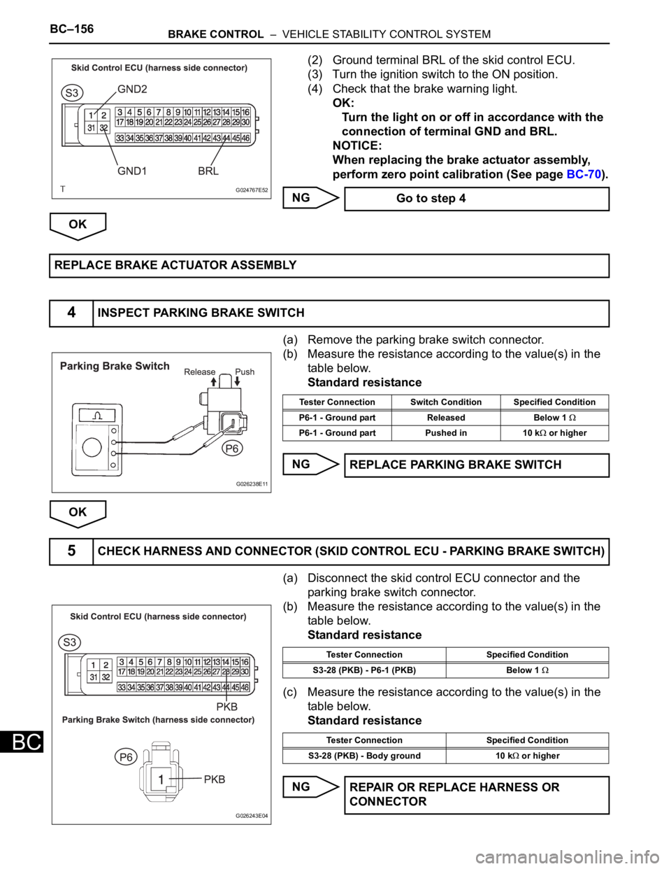
(2) Ground terminal BRL of the skid control ECU.
(3) Turn the ignition switch to the ON position.
(4) Check that the brake warning light.
OK:
Turn the light on or off in accordance with the
connection of terminal GND and BRL.
NOTICE:
When replacing the brake actuator assembly,
perform zero point calibration (See page BC-70).
NG
OK
(a) Remove the parking brake switch connector.
(b) Measure the resistance according to the value(s) in the
table below.
Standard resistance
NG
OK
(a) Disconnect the skid control ECU connector and the
parking brake switch connector.
(b) Measure the resistance according to the value(s) in the
table below.
Standard resistance
(c) Measure the resistance according to the value(s) in the
table below.
Standard resistance
NG
G024767E52 Go to step 4
REPLACE BRAKE ACTUATOR ASSEMBLY
4INSPECT PARKING BRAKE SWITCH
G026238E11
Tester Connection Switch Condition Specified Condition
P6-1 - Ground part Released Below 1
P6-1 - Ground part Pushed in 10 k or higher
REPLACE PARKING BRAKE SWITCH
5CHECK HARNESS AND CONNECTOR (SKID CONTROL ECU - PARKING BRAKE SWITCH)
G026243E04
Tester Connection Specified Condition
S3-28 (PKB) - P6-1 (PKB) Below 1
Tester Connection Specified Condition
S3-28 (PKB) - Body ground 10 k
or higher
REPAIR OR REPLACE HARNESS OR
CONNECTOR
Page 2521 of 3000
BRAKE CONTROL – VEHICLE STABILITY CONTROL SYSTEMBC–159
BC
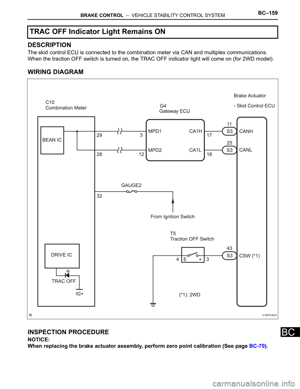
DESCRIPTION
The skid control ECU is connected to the combination meter via CAN and multiplex communications.
When the traction OFF switch is turned on, the TRAC OFF indicator light will come on (for 2WD model).
WIRING DIAGRAM
INSPECTION PROCEDURE
NOTICE:
When replacing the brake actuator assembly, perform zero point calibration (See page BC-70).
TRAC OFF Indicator Light Remains ON
C159741E02
Page 2526 of 3000
BC–164BRAKE CONTROL – VEHICLE STABILITY CONTROL SYSTEM
BC
DESCRIPTION
The skid control ECU is connected to the combination meter via CAN and multiplex communications.
When the traction OFF switch is turned on, the TRAC OFF indicator light will come on (for 2WD model).
WIRING DIAGRAM
Refer to TRAC OFF Indicator Light Remains ON (See page BC-157).
INSPECTION PROCEDURE
NOTICE:
When replacing the brake actuator assembly, perform zero point calibration (See page BC-70).
(a) Check if the CAN communication system DTC is output
(See page CA-17).
Result
B
A
(a) Check if the multiplex communication system DTC is
output (See page MP-14).
Result
B
A
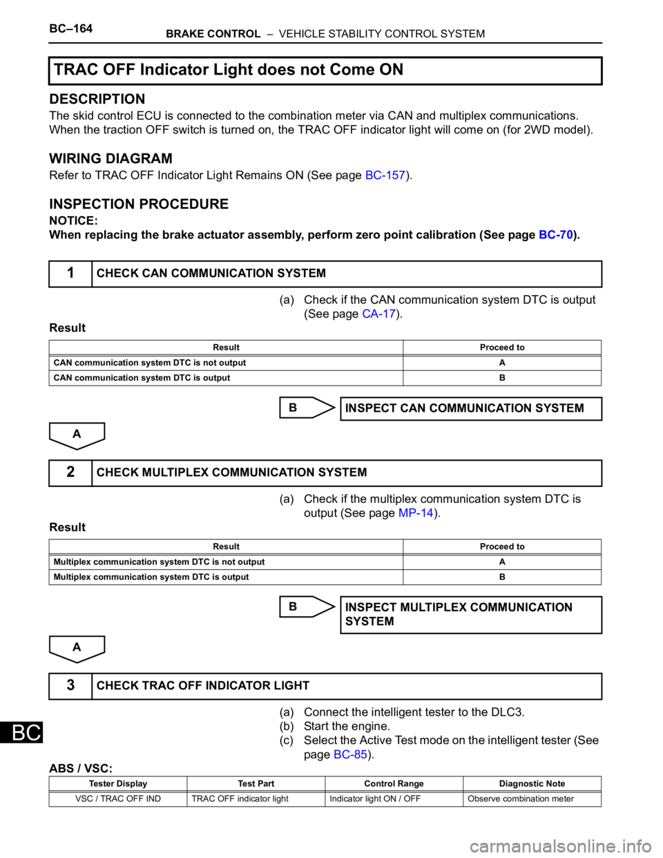
(a) Connect the intelligent tester to the DLC3.
(b) Start the engine.
(c) Select the Active Test mode on the intelligent tester (See
page BC-85).
ABS / VSC:
TRAC OFF Indicator Light does not Come ON
1CHECK CAN COMMUNICATION SYSTEM
Result Proceed to
CAN communication system DTC is not output A
CAN communication system DTC is output B
INSPECT CAN COMMUNICATION SYSTEM
2CHECK MULTIPLEX COMMUNICATION SYSTEM
Result Proceed to
Multiplex communication system DTC is not output A
Multiplex communication system DTC is output B
INSPECT MULTIPLEX COMMUNICATION
SYSTEM
3CHECK TRAC OFF INDICATOR LIGHT
Tester Display Test Part Control Range Diagnostic Note
VSC / TRAC OFF IND TRAC OFF indicator light Indicator light ON / OFF Observe combination meter
Page 2528 of 3000
BC–166BRAKE CONTROL – VEHICLE STABILITY CONTROL SYSTEM
BC
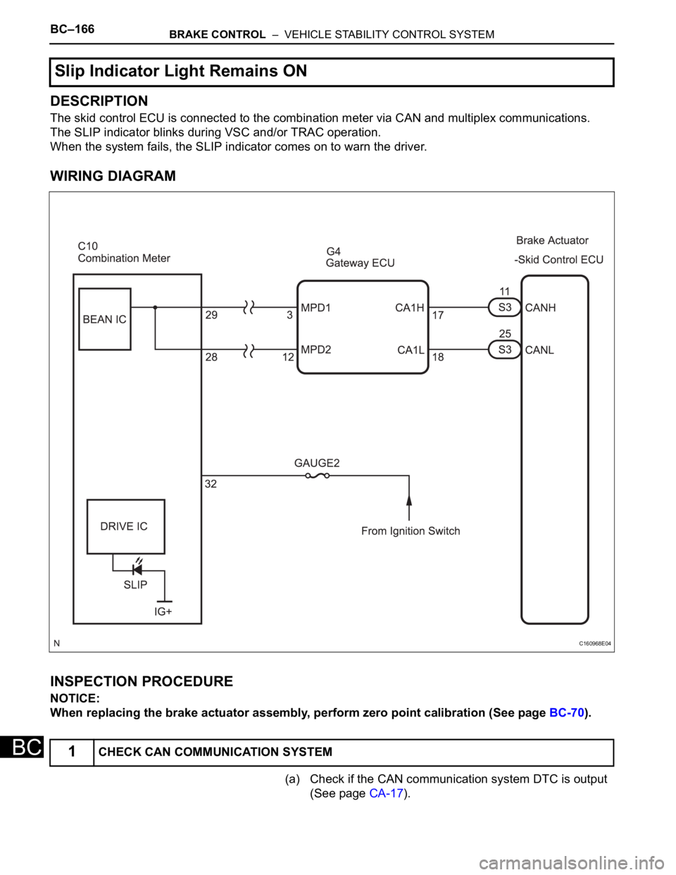
DESCRIPTION
The skid control ECU is connected to the combination meter via CAN and multiplex communications.
The SLIP indicator blinks during VSC and/or TRAC operation.
When the system fails, the SLIP indicator comes on to warn the driver.
WIRING DIAGRAM
INSPECTION PROCEDURE
NOTICE:
When replacing the brake actuator assembly, perform zero point calibration (See page BC-70).
(a) Check if the CAN communication system DTC is output
(See page CA-17).
Slip Indicator Light Remains ON
1CHECK CAN COMMUNICATION SYSTEM
C160968E04
Page 2531 of 3000
BRAKE CONTROL – VEHICLE STABILITY CONTROL SYSTEMBC–169
BC
DESCRIPTION
The skid control ECU is connected to the combination meter via CAN and multiplex communications.
The SLIP indicator blinks during VSC and/or TRAC operation.
When the system fails, the SLIP indicator comes on to warn the driver.
WIRING DIAGRAM
Refer to Slip Indicator Light Remains ON (See page BC-164).
INSPECTION PROCEDURE
NOTICE:
When replacing the brake actuator assembly, perform zero point calibration (See page BC-70).
(a) Check if the CAN communication system DTC is output
(See page CA-17).
Result
B
A
(a) Check if the multiplex communication system DTC is
output (See page MP-14).
Result
B
A
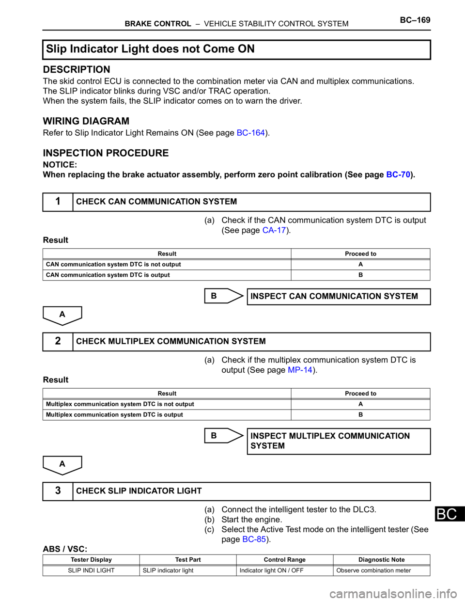
(a) Connect the intelligent tester to the DLC3.
(b) Start the engine.
(c) Select the Active Test mode on the intelligent tester (See
page BC-85).
ABS / VSC:
Slip Indicator Light does not Come ON
1CHECK CAN COMMUNICATION SYSTEM
Result Proceed to
CAN communication system DTC is not output A
CAN communication system DTC is output B
INSPECT CAN COMMUNICATION SYSTEM
2CHECK MULTIPLEX COMMUNICATION SYSTEM
Result Proceed to
Multiplex communication system DTC is not output A
Multiplex communication system DTC is output B
INSPECT MULTIPLEX COMMUNICATION
SYSTEM
3CHECK SLIP INDICATOR LIGHT
Tester Display Test Part Control Range Diagnostic Note
SLIP INDI LIGHT SLIP indicator light Indicator light ON / OFF Observe combination meter
Page 2534 of 3000
BC–172BRAKE CONTROL – VEHICLE STABILITY CONTROL SYSTEM
BC
OK
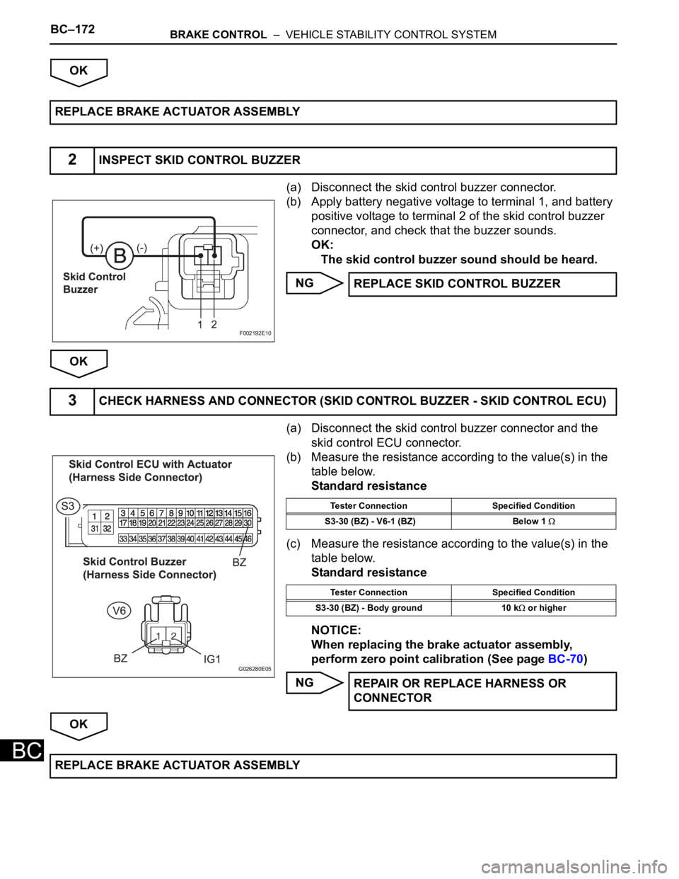
(a) Disconnect the skid control buzzer connector.
(b) Apply battery negative voltage to terminal 1, and battery
positive voltage to terminal 2 of the skid control buzzer
connector, and check that the buzzer sounds.
OK:
The skid control buzzer sound should be heard.
NG
OK
(a) Disconnect the skid control buzzer connector and the
skid control ECU connector.
(b) Measure the resistance according to the value(s) in the
table below.
Standard resistance
(c) Measure the resistance according to the value(s) in the
table below.
Standard resistance
NOTICE:
When replacing the brake actuator assembly,
perform zero point calibration (See page BC-70)
NG
OK REPLACE BRAKE ACTUATOR ASSEMBLY
2INSPECT SKID CONTROL BUZZER
F002192E10
REPLACE SKID CONTROL BUZZER
3CHECK HARNESS AND CONNECTOR (SKID CONTROL BUZZER - SKID CONTROL ECU)
G026280E05
Tester Connection Specified Condition
S3-30 (BZ) - V6-1 (BZ) Below 1
Tester Connection Specified Condition
S3-30 (BZ) - Body ground 10 k
or higher
REPAIR OR REPLACE HARNESS OR
CONNECTOR
REPLACE BRAKE ACTUATOR ASSEMBLY
Page 2535 of 3000
BRAKE CONTROL – VEHICLE STABILITY CONTROL SYSTEMBC–173
BC
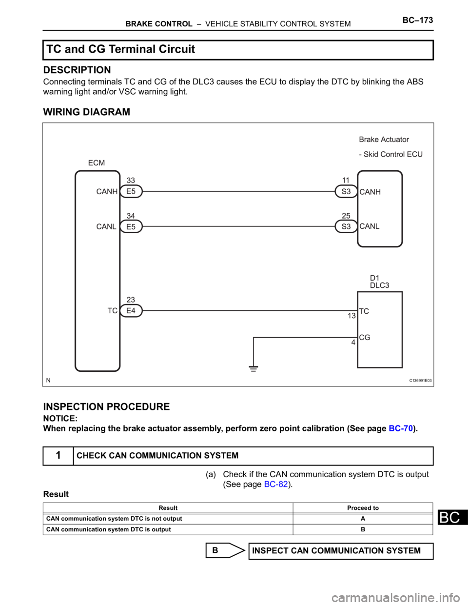
DESCRIPTION
Connecting terminals TC and CG of the DLC3 causes the ECU to display the DTC by blinking the ABS
warning light and/or VSC warning light.
WIRING DIAGRAM
INSPECTION PROCEDURE
NOTICE:
When replacing the brake actuator assembly, perform zero point calibration (See page BC-70).
(a) Check if the CAN communication system DTC is output
(See page BC-82).
Result
B
TC and CG Terminal Circuit
1CHECK CAN COMMUNICATION SYSTEM
C136991E03
Result Proceed to
CAN communication system DTC is not output A
CAN communication system DTC is output B
INSPECT CAN COMMUNICATION SYSTEM
Page 2540 of 3000
BC–178BRAKE CONTROL – VEHICLE STABILITY CONTROL SYSTEM
BC
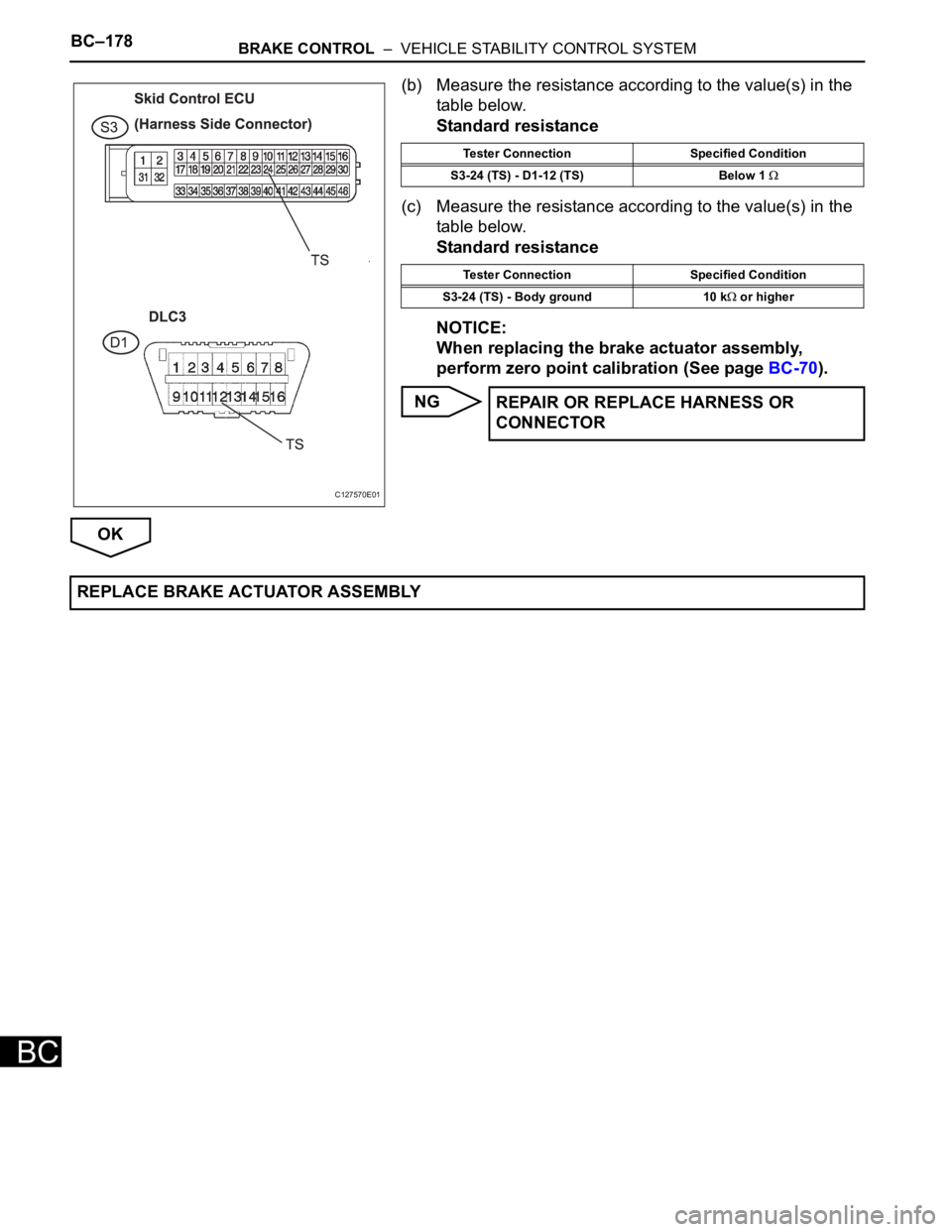
(b) Measure the resistance according to the value(s) in the
table below.
Standard resistance
(c) Measure the resistance according to the value(s) in the
table below.
Standard resistance
NOTICE:
When replacing the brake actuator assembly,
perform zero point calibration (See page BC-70).
NG
OK
C127570E01
Tester Connection Specified Condition
S3-24 (TS) - D1-12 (TS) Below 1
Tester Connection Specified Condition
S3-24 (TS) - Body ground 10 k
or higher
REPAIR OR REPLACE HARNESS OR
CONNECTOR
REPLACE BRAKE ACTUATOR ASSEMBLY