2007 TOYOTA SIENNA fog light
[x] Cancel search: fog lightPage 55 of 3000
INTRODUCTION – HOW TO TROUBLESHOOT ECU CONTROLLED SYSTEMSIN–43
IN
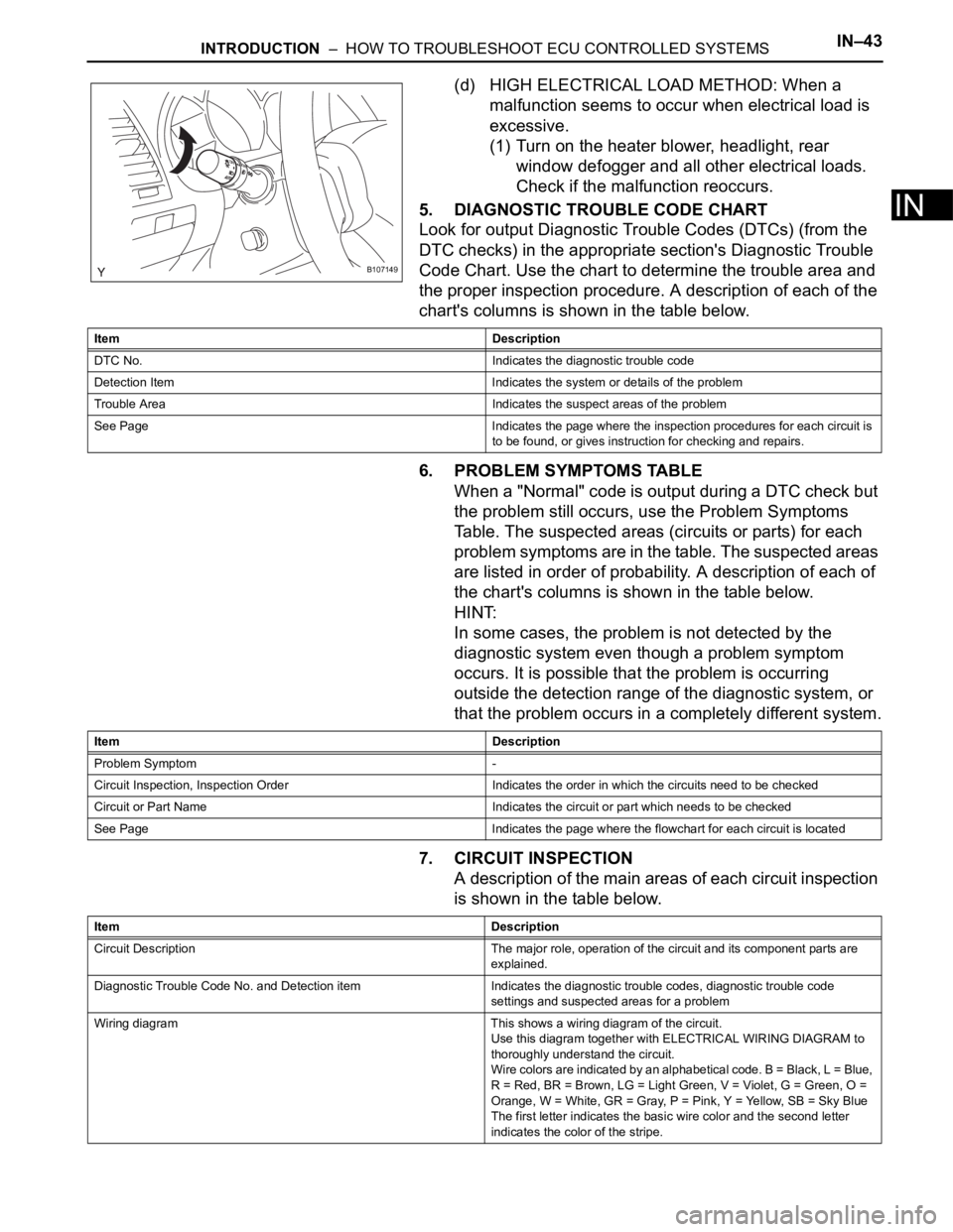
(d) HIGH ELECTRICAL LOAD METHOD: When a
malfunction seems to occur when electrical load is
excessive.
(1) Turn on the heater blower, headlight, rear
window defogger and all other electrical loads.
Check if the malfunction reoccurs.
5. DIAGNOSTIC TROUBLE CODE CHART
Look for output Diagnostic Trouble Codes (DTCs) (from the
DTC checks) in the appropriate section's Diagnostic Trouble
Code Chart. Use the chart to determine the trouble area and
the proper inspection procedure. A description of each of the
chart's columns is shown in the table below.
6. PROBLEM SYMPTOMS TABLE
When a "Normal" code is output during a DTC check but
the problem still occurs, use the Problem Symptoms
Table. The suspected areas (circuits or parts) for each
problem symptoms are in the table. The suspected areas
are listed in order of probability. A description of each of
the chart's columns is shown in the table below.
HINT:
In some cases, the problem is not detected by the
diagnostic system even though a problem symptom
occurs. It is possible that the problem is occurring
outside the detection range of the diagnostic system, or
that the problem occurs in a completely different system.
7. CIRCUIT INSPECTION
A description of the main areas of each circuit inspection
is shown in the table below.
B107149
Item Description
DTC No. Indicates the diagnostic trouble code
Detection Item Indicates the system or details of the problem
Trouble Area Indicates the suspect areas of the problem
See Page Indicates the page where the inspection procedures for each circuit is
to be found, or gives instruction for checking and repairs.
Item Description
Problem Symptom -
Circuit Inspection, Inspection Order Indicates the order in which the circuits need to be checked
Circuit or Part Name Indicates the circuit or part which needs to be checked
See Page Indicates the page where the flowchart for each circuit is located
Item Description
Circuit Description The major role, operation of the circuit and its component parts are
explained.
Diagnostic Trouble Code No. and Detection item Indicates the diagnostic trouble codes, diagnostic trouble code
settings and suspected areas for a problem
Wiring diagram This shows a wiring diagram of the circuit.
Use this diagram together with ELECTRICAL WIRING DIAGRAM to
thoroughly understand the circuit.
Wire colors are indicated by an alphabetical code. B = Black, L = Blue,
R = Red, BR = Brown, LG = Light Green, V = Violet, G = Green, O =
Orange, W = White, GR = Gray, P = Pink, Y = Yellow, SB = Sky Blue
The first letter indicates the basic wire color and the second letter
indicates the color of the stripe.
Page 73 of 3000
INTRODUCTION – HOW TO TROUBLESHOOT ECU CONTROLLED SYSTEMSIN–43
IN
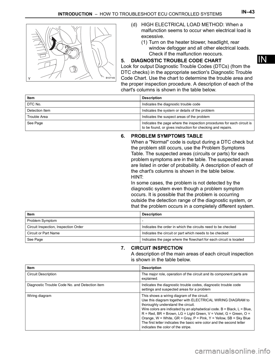
(d) HIGH ELECTRICAL LOAD METHOD: When a
malfunction seems to occur when electrical load is
excessive.
(1) Turn on the heater blower, headlight, rear
window defogger and all other electrical loads.
Check if the malfunction reoccurs.
5. DIAGNOSTIC TROUBLE CODE CHART
Look for output Diagnostic Trouble Codes (DTCs) (from the
DTC checks) in the appropriate section's Diagnostic Trouble
Code Chart. Use the chart to determine the trouble area and
the proper inspection procedure. A description of each of the
chart's columns is shown in the table below.
6. PROBLEM SYMPTOMS TABLE
When a "Normal" code is output during a DTC check but
the problem still occurs, use the Problem Symptoms
Table. The suspected areas (circuits or parts) for each
problem symptoms are in the table. The suspected areas
are listed in order of probability. A description of each of
the chart's columns is shown in the table below.
HINT:
In some cases, the problem is not detected by the
diagnostic system even though a problem symptom
occurs. It is possible that the problem is occurring
outside the detection range of the diagnostic system, or
that the problem occurs in a completely different system.
7. CIRCUIT INSPECTION
A description of the main areas of each circuit inspection
is shown in the table below.
B107149
Item Description
DTC No. Indicates the diagnostic trouble code
Detection Item Indicates the system or details of the problem
Trouble Area Indicates the suspect areas of the problem
See Page Indicates the page where the inspection procedures for each circuit is
to be found, or gives instruction for checking and repairs.
Item Description
Problem Symptom -
Circuit Inspection, Inspection Order Indicates the order in which the circuits need to be checked
Circuit or Part Name Indicates the circuit or part which needs to be checked
See Page Indicates the page where the flowchart for each circuit is located
Item Description
Circuit Description The major role, operation of the circuit and its component parts are
explained.
Diagnostic Trouble Code No. and Detection item Indicates the diagnostic trouble codes, diagnostic trouble code
settings and suspected areas for a problem
Wiring diagram This shows a wiring diagram of the circuit.
Use this diagram together with ELECTRICAL WIRING DIAGRAM to
thoroughly understand the circuit.
Wire colors are indicated by an alphabetical code. B = Black, L = Blue,
R = Red, BR = Brown, LG = Light Green, V = Violet, G = Green, O =
Orange, W = White, GR = Gray, P = Pink, Y = Yellow, SB = Sky Blue
The first letter indicates the basic wire color and the second letter
indicates the color of the stripe.
Page 211 of 3000

AIR CONDITIONING – CONDENSERAC–241
AC
18. VEHICLE PREPARATION FOR FOG LIGHT AIMING
(w/ Fog Light) (See page LI-82)
19. PREPARATION FOR FOG LIGHT AIMING (w/ Fog
Light) (See page LI-83)
20. FOG LIGHT AIMING INSPECTION (w/ Fog Light) (See
page LI-84)
21. FOG LIGHT AIMING ADJUSTMENT (w/ Fog Light)
(See page LI-85)
Page 283 of 3000
WS–66WINDSHIELD / WINDOWGLASS – WINDOW DEFOGGER SYSTEM
WS
PROBLEM SYMPTOMS TABLE
WINDOW DEFOGGER SYSTEM
ON-VEHICLE INSPECTION
1. INSPECT BACK WINDOW (DEFOGGER WIRE)
NOTICE:
• When cleaning the glass, wipe the glass along the
wire using a soft and dry cloth. Take care not to
damage the wires.
• Do not use detergents or glass cleaners including
abrasive ingredients.
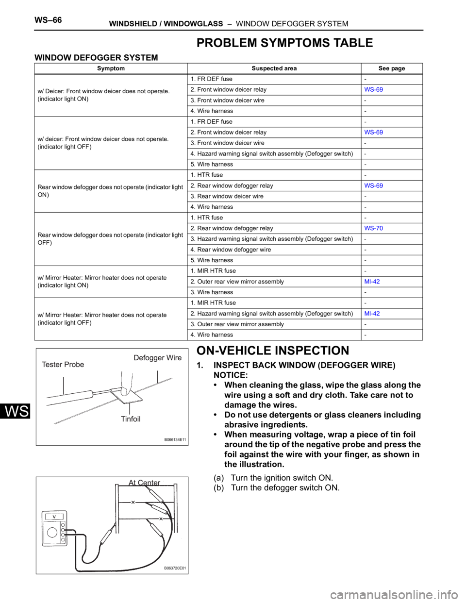
• When measuring voltage, wrap a piece of tin foil
around the tip of the negative probe and press the
foil against the wire with your finger, as shown in
the illustration.
(a) Turn the ignition switch ON.
(b) Turn the defogger switch ON.
Symptom Suspected area See page
w/ Deicer: Front window deicer does not operate.
(indicator light ON)1. FR DEF fuse -
2. Front window deicer relayWS-69
3. Front window deicer wire -
4. Wire harness -
w/ deicer: Front window deicer does not operate.
(indicator light OFF)1. FR DEF fuse -
2. Front window deicer relayWS-69
3. Front window deicer wire -
4. Hazard warning signal switch assembly (Defogger switch) -
5. Wire harness -
Rear window defogger does not operate (indicator light
ON)1. HTR fuse -
2. Rear window defogger relayWS-69
3. Rear window deicer wire -
4. Wire harness -
Rear window defogger does not operate (indicator light
OFF)1. HTR fuse -
2. Rear window defogger relayWS-70
3. Hazard warning signal switch assembly (Defogger switch) -
4. Rear window defogger wire -
5. Wire harness -
w/ Mirror Heater: Mirror heater does not operate
(indicator light ON)1. MIR HTR fuse -
2. Outer rear view mirror assemblyMI-42
3. Wire harness -
w/ Mirror Heater: Mirror heater does not operate
(indicator light OFF)1. MIR HTR fuse -
2. Hazard warning signal switch assembly (Defogger switch)MI-42
3. Outer rear view mirror assembly -
4. Wire harness -
B066134E11
B063720E01
Page 1264 of 3000
CO–462GR-FE COOLING – RADIATOR
CO
24. INSTALL BATTERY (See page EM-59)
25. INSTALL NO. 2 AIR CLEANER INLET (See page EM-
60)
26. ADD ENGINE COOLANT (See page CO-7)
27. INSPECT FOR COOLANT LEAK (See page CO-1)
28. ADD AUTOMATIC TRANSAXLE FLUID
29. CHECK AUTOMATIC TRANSAXLE FLUID (See page
AX-123)
30. INSTALL NO. 1 ENGINE UNDER COVER (See page
EM-63)
31. INSTALL V-BANK COVER SUB-ASSEMBLY (See
page EM-63)
32. VEHICLE PREPARATION FOR HEADLIGHT AIM
ADJUSTMENT (See page LI-71)
33. PREPARATION FOR HEADLIGHT AIMING (Using a
tester) (See page LI-71)
34. PREPARATION FOR HEADLIGHT AIMING (Using a
screen) (See page LI-72)
35. HEADLIGHT AIMING INSPECTION (See page LI-74)
36. HEADLIGHT AIMING ADJUSTMENT (See page LI-75)
37. VEHICLE PREPARATION FOR FOG LIGHT AIM
ADJUSTMENT (w/ Fog Light) (See page LI-82)
38. PREPARATION FOR FOG LIGHT AIMING (Using a
screen) (w/ Fog Light) (See page LI-83)
39. FOG LIGHT AIMING INSPECTION (w/ Fog Light) (See
page LI-84)
40. FOG LIGHT AIMING ADJUSTMENT (w/ Fog Light)
(See page LI-85)
Page 1291 of 3000
CO–462GR-FE COOLING – RADIATOR
CO
24. INSTALL BATTERY (See page EM-59)
25. INSTALL NO. 2 AIR CLEANER INLET (See page EM-
60)
26. ADD ENGINE COOLANT (See page CO-7)
27. INSPECT FOR COOLANT LEAK (See page CO-1)
28. ADD AUTOMATIC TRANSAXLE FLUID
29. CHECK AUTOMATIC TRANSAXLE FLUID (See page
AX-123)
30. INSTALL NO. 1 ENGINE UNDER COVER (See page
EM-63)
31. INSTALL V-BANK COVER SUB-ASSEMBLY (See
page EM-63)
32. VEHICLE PREPARATION FOR HEADLIGHT AIM
ADJUSTMENT (See page LI-71)
33. PREPARATION FOR HEADLIGHT AIMING (Using a
tester) (See page LI-71)
34. PREPARATION FOR HEADLIGHT AIMING (Using a
screen) (See page LI-72)
35. HEADLIGHT AIMING INSPECTION (See page LI-74)
36. HEADLIGHT AIMING ADJUSTMENT (See page LI-75)
37. VEHICLE PREPARATION FOR FOG LIGHT AIM
ADJUSTMENT (w/ Fog Light) (See page LI-82)
38. PREPARATION FOR FOG LIGHT AIMING (Using a
screen) (w/ Fog Light) (See page LI-83)
39. FOG LIGHT AIMING INSPECTION (w/ Fog Light) (See
page LI-84)
40. FOG LIGHT AIMING ADJUSTMENT (w/ Fog Light)
(See page LI-85)
Page 1341 of 3000
CH–62GR-FE CHARGING – CHARGING SYSTEM
CH
ON-VEHICLE INSPECTION
1. CHECK BATTERY ELECTROLYTE LEVEL
(a) Check the electrolyte level.
(1) If the electrolyte level is low, replace the battery
(or add distilled water) and check the charging
system.
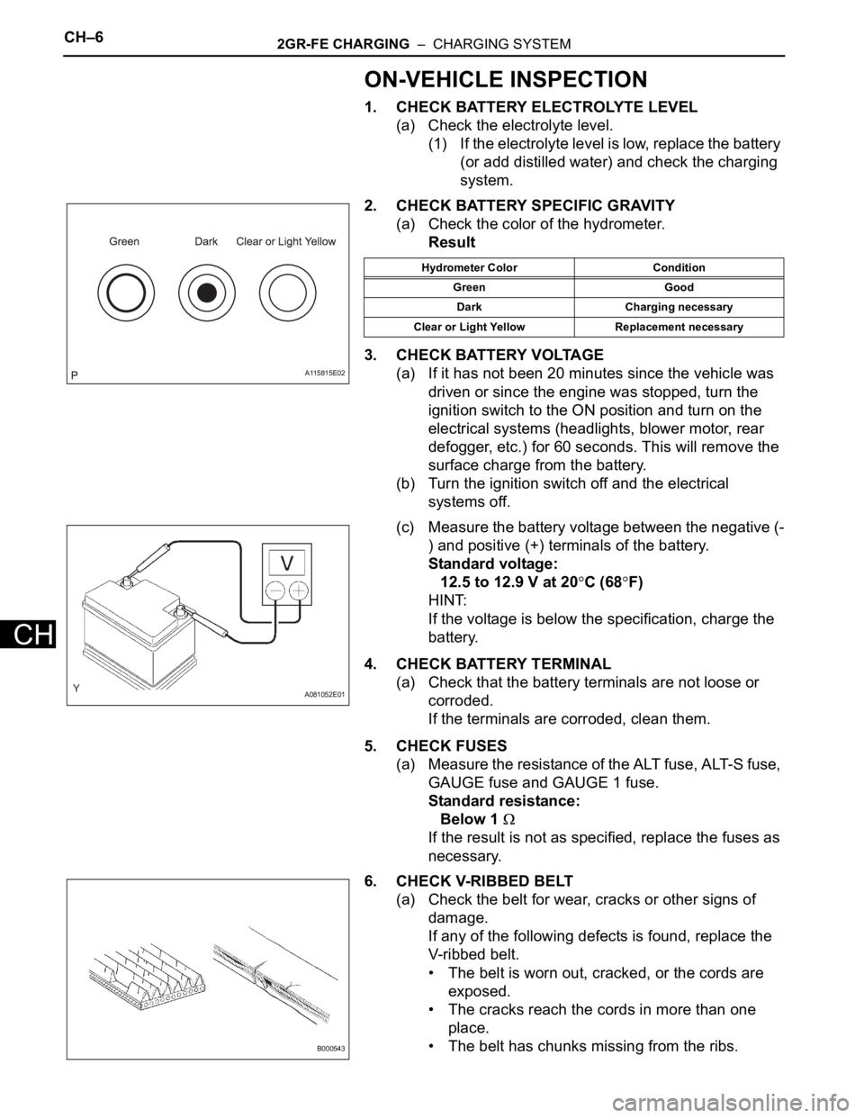
2. CHECK BATTERY SPECIFIC GRAVITY
(a) Check the color of the hydrometer.
Result
3. CHECK BATTERY VOLTAGE
(a) If it has not been 20 minutes since the vehicle was
driven or since the engine was stopped, turn the
ignition switch to the ON position and turn on the
electrical systems (headlights, blower motor, rear
defogger, etc.) for 60 seconds. This will remove the
surface charge from the battery.
(b) Turn the ignition switch off and the electrical
systems off.
(c) Measure the battery voltage between the negative (-
) and positive (+) terminals of the battery.
Standard voltage:
12.5 to 12.9 V at 20
C (68F)
HINT:
If the voltage is below the specification, charge the
battery.
4. CHECK BATTERY TERMINAL
(a) Check that the battery terminals are not loose or
corroded.
If the terminals are corroded, clean them.
5. CHECK FUSES
(a) Measure the resistance of the ALT fuse, ALT-S fuse,
GAUGE fuse and GAUGE 1 fuse.
Standard resistance:
Below 1
If the result is not as specified, replace the fuses as
necessary.
6. CHECK V-RIBBED BELT
(a) Check the belt for wear, cracks or other signs of
damage.
If any of the following defects is found, replace the
V-ribbed belt.
• The belt is worn out, cracked, or the cords are
exposed.
• The cracks reach the cords in more than one
place.
• The belt has chunks missing from the ribs.
A115815E02
Hydrometer Color Condition
Green Good
Dark Charging necessary
Clear or Light Yellow Replacement necessary
A081052E01
B000543
Page 1346 of 3000
CH–62GR-FE CHARGING – CHARGING SYSTEM
CH
ON-VEHICLE INSPECTION
1. CHECK BATTERY ELECTROLYTE LEVEL
(a) Check the electrolyte level.
(1) If the electrolyte level is low, replace the battery
(or add distilled water) and check the charging
system.
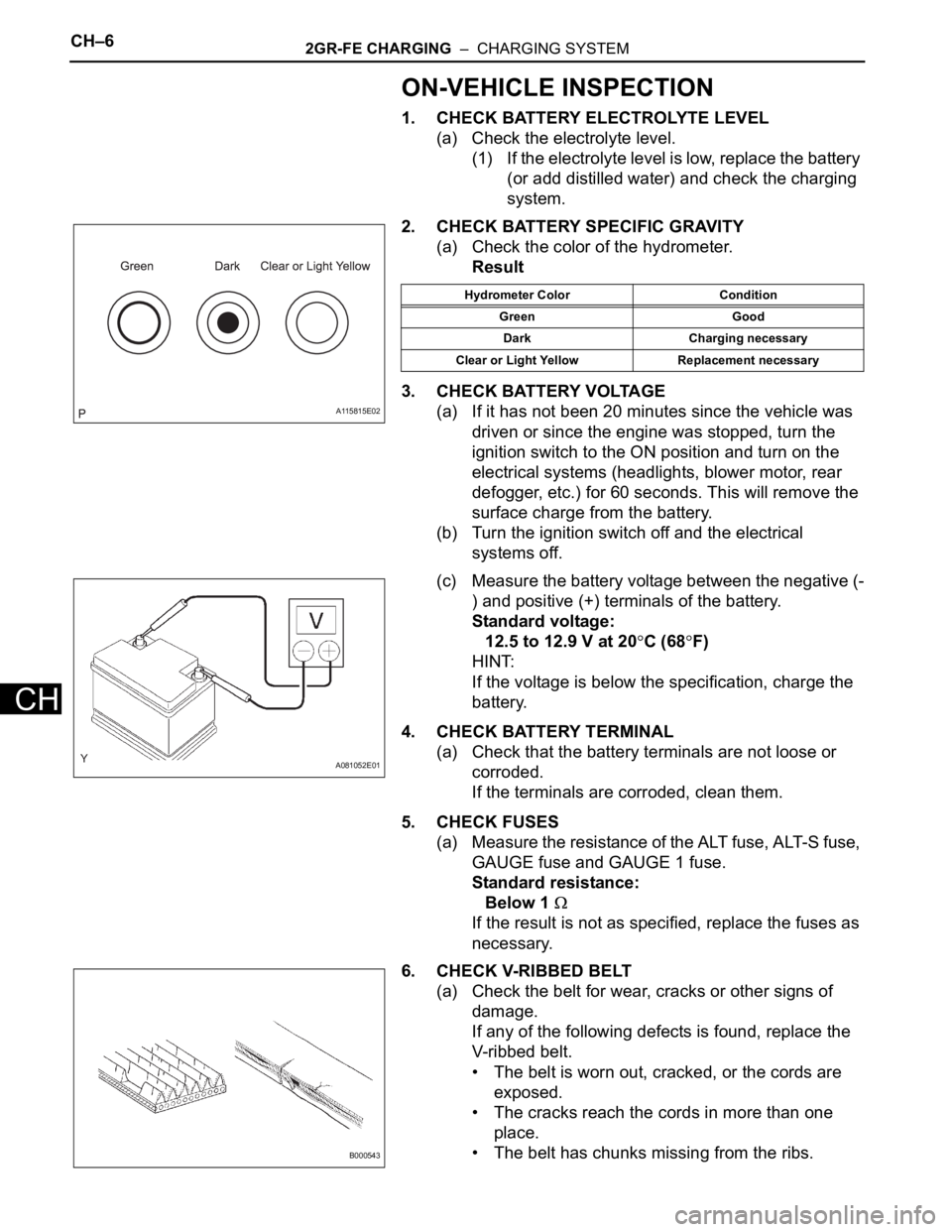
2. CHECK BATTERY SPECIFIC GRAVITY
(a) Check the color of the hydrometer.
Result
3. CHECK BATTERY VOLTAGE
(a) If it has not been 20 minutes since the vehicle was
driven or since the engine was stopped, turn the
ignition switch to the ON position and turn on the
electrical systems (headlights, blower motor, rear
defogger, etc.) for 60 seconds. This will remove the
surface charge from the battery.
(b) Turn the ignition switch off and the electrical
systems off.
(c) Measure the battery voltage between the negative (-
) and positive (+) terminals of the battery.
Standard voltage:
12.5 to 12.9 V at 20
C (68F)
HINT:
If the voltage is below the specification, charge the
battery.
4. CHECK BATTERY TERMINAL
(a) Check that the battery terminals are not loose or
corroded.
If the terminals are corroded, clean them.
5. CHECK FUSES
(a) Measure the resistance of the ALT fuse, ALT-S fuse,
GAUGE fuse and GAUGE 1 fuse.
Standard resistance:
Below 1
If the result is not as specified, replace the fuses as
necessary.
6. CHECK V-RIBBED BELT
(a) Check the belt for wear, cracks or other signs of
damage.
If any of the following defects is found, replace the
V-ribbed belt.
• The belt is worn out, cracked, or the cords are
exposed.
• The cracks reach the cords in more than one
place.
• The belt has chunks missing from the ribs.
A115815E02
Hydrometer Color Condition
Green Good
Dark Charging necessary
Clear or Light Yellow Replacement necessary
A081052E01
B000543