Page 1882 of 3000
AX–166U151F AUTOMATIC TRANSAXLE – AUTOMATIC TRANSAXLE ASSEMBLY
AX
11. REMOVE OIL COOLER INLET TUBE NO.1
(a) Using SST and a wrench, disconnect the oil cooler
inlet tube No.1.
SST 09023-12701
12. REMOVE OIL COOLER OUTLET TUBE NO.1
(a) Using SST and a wrench, disconnect the oil cooler
outlet tube No.1.
SST 09023-12701
13. REMOVE ENGINE MOUNTING BRACKET FRONT
(a) Remove the 3 bolts and engine mounting bracket
front.
14. REMOVE TRANSFER STIFFENER PLATE RH
(a) Remove the 5 bolts and transfer stiffener plate RH.
15. REMOVE AUTOMATIC TRANSAXLE W/TRANSFER
(a) Remove the 2 bolts and flywheel housing under
cover.
(b) Turn the crankshaft to gain access and remove the
6 bolts while holding the crankshaft pulley bolt with a
wrench.
HINT:
There will be one green colored bolt.
D030469E03
D030470
D030512
D030471
D030472
Page 1885 of 3000

U151F AUTOMATIC TRANSAXLE – AUTOMATIC TRANSAXLE ASSEMBLYAX–169
AX
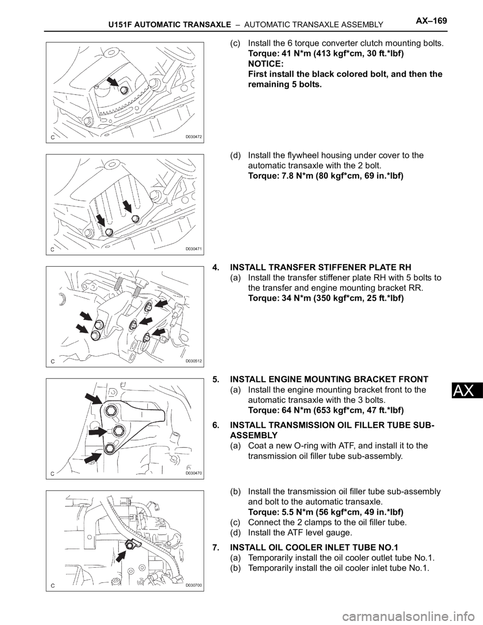
(c) Install the 6 torque converter clutch mounting bolts.
Torque: 41 N*m (413 kgf*cm, 30 ft.*lbf)
NOTICE:
First install the black colored bolt, and then the
remaining 5 bolts.
(d) Install the flywheel housing under cover to the
automatic transaxle with the 2 bolt.
Torque: 7.8 N*m (80 kgf*cm, 69 in.*lbf)
4. INSTALL TRANSFER STIFFENER PLATE RH
(a) Install the transfer stiffener plate RH with 5 bolts to
the transfer and engine mounting bracket RR.
Torque: 34 N*m (350 kgf*cm, 25 ft.*lbf)
5. INSTALL ENGINE MOUNTING BRACKET FRONT
(a) Install the engine mounting bracket front to the
automatic transaxle with the 3 bolts.
Torque: 64 N*m (653 kgf*cm, 47 ft.*lbf)
6. INSTALL TRANSMISSION OIL FILLER TUBE SUB-
ASSEMBLY
(a) Coat a new O-ring with ATF, and install it to the
transmission oil filler tube sub-assembly.
(b) Install the transmission oil filler tube sub-assembly
and bolt to the automatic transaxle.
Torque: 5.5 N*m (56 kgf*cm, 49 in.*lbf)
(c) Connect the 2 clamps to the oil filler tube.
(d) Install the ATF level gauge.
7. INSTALL OIL COOLER INLET TUBE NO.1
(a) Temporarily install the oil cooler outlet tube No.1.
(b) Temporarily install the oil cooler inlet tube No.1.
D030472
D030471
D030512
D030470
D030700
Page 2159 of 3000

AXLE – REAR AXLE HUB AND BEARING (for 2WD)AH–17
AH
REMOVAL
HINT:
Replace the RH side by the same procedures as the LH side.
1. REMOVE REAR WHEEL
2. REMOVE REAR DISC BRAKE CALIPER ASSEMBLY
LH
(a) Removing the 2 bolts, separate the rear disc brake
caliper assembly LH for disc rear brake type.
NOTICE:
Using a string and so on, hang down the disc
brake caliper.
3. REMOVE REAR DISC
(a) Remove rear disc for disc rear brake type.
4. REMOVE REAR BRAKE DRUM SUB-ASSEMBLY
(a) Remove rear brake drum sub-assembly for drum
rear brake type.
5. SEPARATE SKID CONTROL SENSOR WIRE
(a) Disconnect the connector
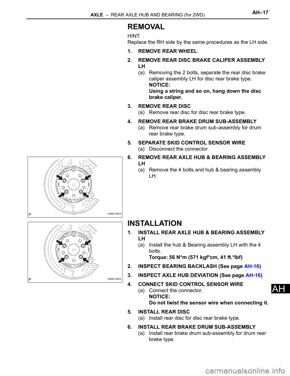
6. REMOVE REAR AXLE HUB & BEARING ASSEMBLY
LH
(a) Remove the 4 bolts and hub & bearing assembly
LH.
INSTALLATION
1. INSTALL REAR AXLE HUB & BEARING ASSEMBLY
LH
(a) Install the hub & Bearing assembly LH with the 4
bolts.
Torque: 56 N*m (571 kgf*cm, 41 ft.*lbf)
2. INSPECT BEARING BACKLASH (See page AH-16)
3. INSPECT AXLE HUB DEVIATION (See page AH-16)
4. CONNECT SKID CONTROL SENSOR WIRE
(a) Connect the connector.
NOTICE:
Do not twist the sensor wire when connecting it.
5. INSTALL REAR DISC
(a) Install rear disc for disc rear brake type.
6. INSTALL REAR BRAKE DRUM SUB-ASSEMBLY
(a) Install rear brake drum sub-assembly for drum rear
brake type.
C066210E04
C066210E05
Page 2160 of 3000
AH–18AXLE – REAR AXLE HUB AND BEARING (for 2WD)
AH
7. INSTALL REAR DISC BRAKE CALIPER ASSEMBLY
LH
(a) Install the rear disc brake caliper assembly LH with
the 2 bolts for disc rear brake type.
Torque: 88 N*m (900 kgf*cm, 65 ft.*lbf)
8. INSTALL REAR WHEEL
Torque: 103 N*m (1,050 kgf*cm, 76 ft.*lbf)
9. CHECK ABS SPEED SENSOR SIGNAL
(a) ABS WITH EBD SYSTEM (See page BC-3).
(b) ABS WITH EBD & BA & TRAC & VSC SYSTEM
(See page BC-72).
Page 2161 of 3000

AH–20AXLE – REAR AXLE HUB AND BEARING (for 4WD)
AH
REMOVAL
HINT:
Replace the RH side by the same procedures as the LH side.
1. REMOVE REAR WHEEL
2. REMOVE REAR AXLE SHAFT LH NUT (See page DS-
22)
3. SEPARATE REAR DISC BRAKE CALIPER
ASSEMBLY LH
(a) Removing the 2 bolts, separate the rear disc brake
caliper assembly LH.
4. REMOVE REAR DISC
5. SEPARATE SPEED SENSOR REAR LH
(a) Removing the bolt, separate the speed sensor rear
LH.
NOTICE:
• Be careful not to damage the speed sensor.
• Prevent foreign matter from attaching to the
speed sensor.
6. REMOVE REAR DRIVE SHAFT ASSEMBLY LH (See
page DS-22)
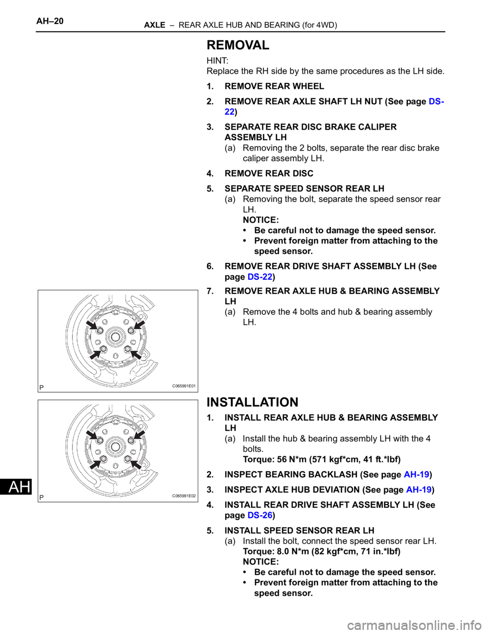
7. REMOVE REAR AXLE HUB & BEARING ASSEMBLY
LH
(a) Remove the 4 bolts and hub & bearing assembly
LH.
INSTALLATION
1. INSTALL REAR AXLE HUB & BEARING ASSEMBLY
LH
(a) Install the hub & bearing assembly LH with the 4
bolts.
Torque: 56 N*m (571 kgf*cm, 41 ft.*lbf)
2. INSPECT BEARING BACKLASH (See page AH-19)
3. INSPECT AXLE HUB DEVIATION (See page AH-19)
4. INSTALL REAR DRIVE SHAFT ASSEMBLY LH (See
page DS-26)
5. INSTALL SPEED SENSOR REAR LH
(a) Install the bolt, connect the speed sensor rear LH.
Torque: 8.0 N*m (82 kgf*cm, 71 in.*lbf)
NOTICE:
• Be careful not to damage the speed sensor.
• Prevent foreign matter from attaching to the
speed sensor.
C065991E01
C065991E02
Page 2162 of 3000
AXLE – REAR AXLE HUB AND BEARING (for 4WD)AH–21
AH
• Do not twist the sensor wire when installing
the sensor.
6. INSTALL REAR DISC
7. INSTALL REAR DISC BRAKE CALIPER ASSEMBLY
LH
(a) Install the rear disc brake caliper assembly LH with
the 2 bolts.
Torque: 88 N*m (900 kgf*cm, 65 ft.*lbf)
8. INSTALL REAR AXLE SHAFT LH NUT (See page DS-
26)
9. INSTALL REAR WHEEL
Torque: 103 N*m (1,050 kgf*cm, 76 ft.*lbf)
10. CHECK ABS SPEED SENSOR SIGNAL
(a) ABS WITH EBD & BA & TRAC & VSC SYSTEM
(See page BC-72).
Page 2165 of 3000
AH–6AXLE – FRONT AXLE HUB
AH
REMOVAL
HINT:
Replace the RH side using the same procedures as for the
LH side.
1. REMOVE FRONT WHEEL
2. REMOVE FRONT AXLE HUB LH NUT (See page DS-
5)
3. SEPARATE SPEED SENSOR FRONT LH (See page
DS-5)
4. SEPARATE FRONT DISC BRAKE CALIPER
ASSEMBLY LH
(a) Remove the 2 bolts and separate the front disc
brake caliper assembly LH from the steering
knuckle LH.
NOTICE:
Use a string or other device to keep the brake
caliper from hanging down.
5. REMOVE FRONT DISC
6. SEPARATE TIE ROD END SUB-ASSEMBLY LH (See
page DS-6)
7. SEPARATE FRONT SUSPENSION ARM SUB-
ASSEMBLY LOWER NO.1 LH (See page DS-6)
8. REMOVE FRONT AXLE ASSEMBLY LH
(a) Using a plastic hammer, separate the front drive
shaft assembly LH from the front axle hub sub-
assembly LH.
NOTICE:
Be careful not to damage the boot and ABS
speed sensor rotor.
(b) Remove the 2 bolts, nuts and steering knuckle LH
with the front axle nub sub-assembly LH.
C067088
D027403
C083023
Page 2166 of 3000
AXLE – FRONT AXLE HUBAH–7
AH
DISASSEMBLY
1. REMOVE LOWER BALL JOINT ASSEMBLY FRONT
LH
(a) Remove the cotter pin and nut.
(b) Using SST(s), remove the lower ball joint assembly
front LH.
SST 09628-62011
2. REMOVE FRONT WHEEL BEARING DUST
DEFLECTOR NO.1 LH
(a) Using a screwdriver, remove the bearing dust
deflector NO. 1 LH.
3. REMOVE FRONT AXLE HUB LH HOLE SNAP RING
(a) Using snap ring pliers, remove the front axle hub LH
hole snap ring.
4. REMOVE FRONT AXLE ASSEMBLY LH
(a) Using SST(s), remove the front axle hub sub-
assembly LH.
SST 09520-00031
(b) Using SST(s) and a press, remove the bearing inner
race (outside) from the front axle hub sub-assembly
LH.
SST 09950-00020, 09950-60010 (09951-00430),
09950-70010 (09951-07100)
5. REMOVE DISC BRAKE DUST COVER FRONT LH
(a) Using a torx wrench (T30), remove the 4 bolts and
disc brake dust cover front LH.
HINT:
Torx is a registered trademark of Textron Inc.
F040153E02
F040154
F045465
F040156E05
F002261E03