Page 2638 of 3000
BR–38BRAKE – REAR DRUM BRAKE
BR
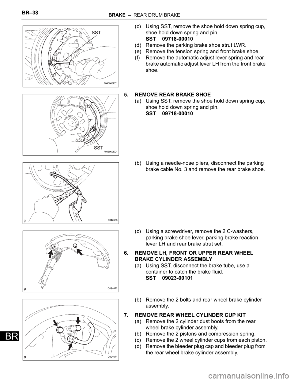
(c) Using SST, remove the shoe hold down spring cup,
shoe hold down spring and pin.
SST 09718-00010
(d) Remove the parking brake shoe strut LWR.
(e) Remove the tension spring and front brake shoe.
(f) Remove the automatic adjust lever spring and rear
brake automatic adjust lever LH from the front brake
shoe.
5. REMOVE REAR BRAKE SHOE
(a) Using SST, remove the shoe hold down spring cup,
shoe hold down spring and pin.
SST 09718-00010
(b) Using a needle-nose pliers, disconnect the parking
brake cable No. 3 and remove the rear brake shoe.
(c) Using a screwdriver, remove the 2 C-washers,
parking brake shoe lever, parking brake reaction
lever LH and rear brake strut set.
6. REMOVE LH, FRONT OR UPPER REAR WHEEL
BRAKE CYLINDER ASSEMBLY
(a) Using SST, disconnect the brake tube, use a
container to catch the brake fluid.
SST 09023-00101
(b) Remove the 2 bolts and rear wheel brake cylinder
assembly.
7. REMOVE REAR WHEEL CYLINDER CUP KIT
(a) Remove the 2 cylinder dust boots from the rear
wheel brake cylinder assembly.
(b) Remove the 2 pistons and compression spring.
(c) Remove the 2 wheel cylinder cups from each piston.
(d) Remove the bleeder plug cap and bleeder plug from
the rear wheel brake cylinder assembly.
F045068E01
F045069E01
F042688
C094672
C094671
Page 2640 of 3000
BR–40BRAKE – REAR DRUM BRAKE
BR
REASSEMBLY
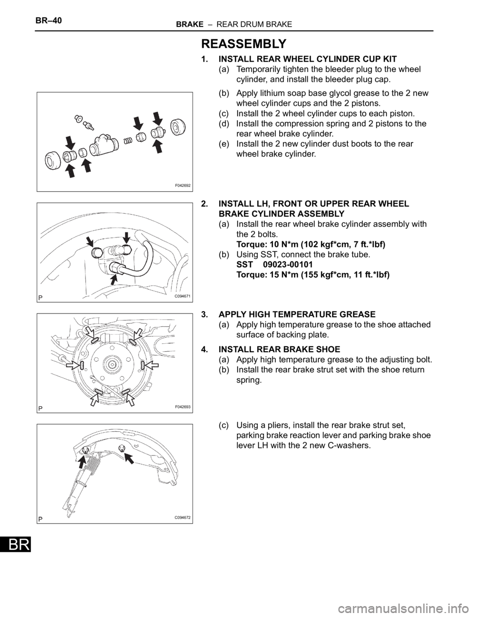
1. INSTALL REAR WHEEL CYLINDER CUP KIT
(a) Temporarily tighten the bleeder plug to the wheel
cylinder, and install the bleeder plug cap.
(b) Apply lithium soap base glycol grease to the 2 new
wheel cylinder cups and the 2 pistons.
(c) Install the 2 wheel cylinder cups to each piston.
(d) Install the compression spring and 2 pistons to the
rear wheel brake cylinder.
(e) Install the 2 new cylinder dust boots to the rear
wheel brake cylinder.
2. INSTALL LH, FRONT OR UPPER REAR WHEEL
BRAKE CYLINDER ASSEMBLY
(a) Install the rear wheel brake cylinder assembly with
the 2 bolts.
Torque: 10 N*m (102 kgf*cm, 7 ft.*lbf)
(b) Using SST, connect the brake tube.
SST 09023-00101
Torque: 15 N*m (155 kgf*cm, 11 ft.*lbf)
3. APPLY HIGH TEMPERATURE GREASE
(a) Apply high temperature grease to the shoe attached
surface of backing plate.
4. INSTALL REAR BRAKE SHOE
(a) Apply high temperature grease to the adjusting bolt.
(b) Install the rear brake strut set with the shoe return
spring.
(c) Using a pliers, install the rear brake strut set,
parking brake reaction lever and parking brake shoe
lever LH with the 2 new C-washers.
F042692
C094671
F042693
C094672
Page 2645 of 3000
BR–40BRAKE – REAR DRUM BRAKE
BR
REASSEMBLY
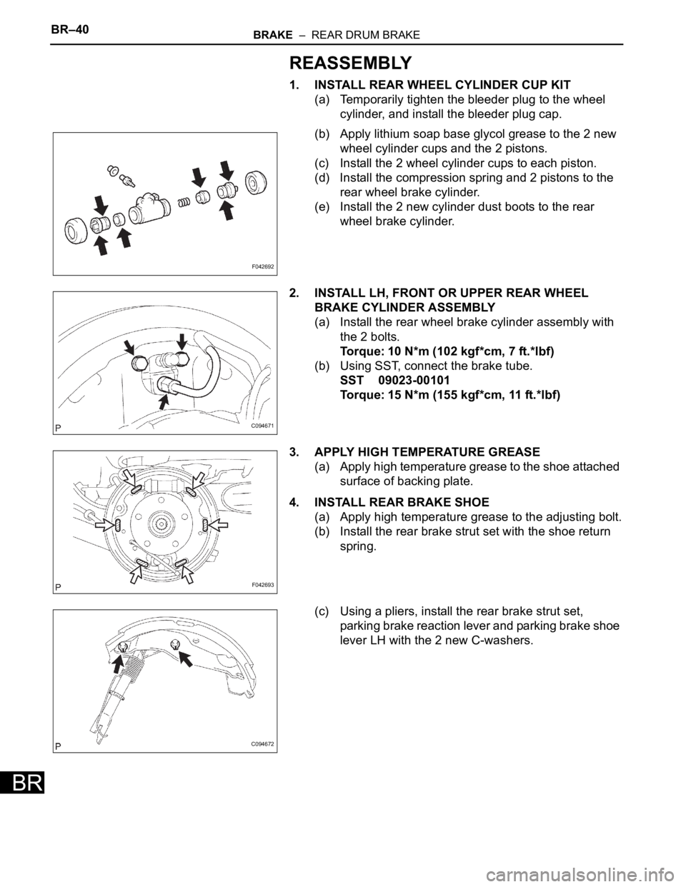
1. INSTALL REAR WHEEL CYLINDER CUP KIT
(a) Temporarily tighten the bleeder plug to the wheel
cylinder, and install the bleeder plug cap.
(b) Apply lithium soap base glycol grease to the 2 new
wheel cylinder cups and the 2 pistons.
(c) Install the 2 wheel cylinder cups to each piston.
(d) Install the compression spring and 2 pistons to the
rear wheel brake cylinder.
(e) Install the 2 new cylinder dust boots to the rear
wheel brake cylinder.
2. INSTALL LH, FRONT OR UPPER REAR WHEEL
BRAKE CYLINDER ASSEMBLY
(a) Install the rear wheel brake cylinder assembly with
the 2 bolts.
Torque: 10 N*m (102 kgf*cm, 7 ft.*lbf)
(b) Using SST, connect the brake tube.
SST 09023-00101
Torque: 15 N*m (155 kgf*cm, 11 ft.*lbf)
3. APPLY HIGH TEMPERATURE GREASE
(a) Apply high temperature grease to the shoe attached
surface of backing plate.
4. INSTALL REAR BRAKE SHOE
(a) Apply high temperature grease to the adjusting bolt.
(b) Install the rear brake strut set with the shoe return
spring.
(c) Using a pliers, install the rear brake strut set,
parking brake reaction lever and parking brake shoe
lever LH with the 2 new C-washers.
F042692
C094671
F042693
C094672
Page 2652 of 3000
PARKING BRAKE – PARKING BRAKE CABLEPB–13
PB
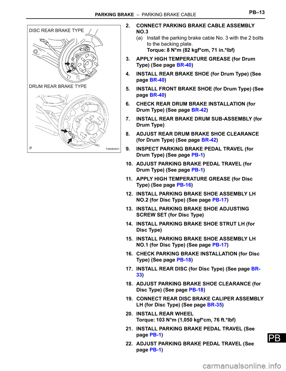
2. CONNECT PARKING BRAKE CABLE ASSEMBLY
NO.3
(a) Install the parking brake cable No. 3 with the 2 bolts
to the backing plate.
Torque: 8 N*m (82 kgf*cm, 71 in.*lbf)
3. APPLY HIGH TEMPERATURE GREASE (for Drum
Type) (See page BR-40)
4. INSTALL REAR BRAKE SHOE (for Drum Type) (See
page BR-40)
5. INSTALL FRONT BRAKE SHOE (for Drum Type) (See
page BR-40)
6. CHECK REAR DRUM BRAKE INSTALLATION (for
Drum Type) (See page BR-42)
7. INSTALL REAR BRAKE DRUM SUB-ASSEMBLY (for
Drum Type)
8. ADJUST REAR DRUM BRAKE SHOE CLEARANCE
(for Drum Type) (See page BR-42)
9. INSPECT PARKING BRAKE PEDAL TRAVEL (for
Drum Type) (See page PB-1)
10. ADJUST PARKING BRAKE PEDAL TRAVEL (for
Drum Type) (See page PB-1)
11. APPLY HIGH TEMPERATURE GREASE (for Disc
Type) (See page PB-16)
12. INSTALL PARKING BRAKE SHOE ASSEMBLY LH
NO.2 (for Disc Type) (See page PB-17)
13. INSTALL PARKING BRAKE SHOE ADJUSTING
SCREW SET (for Disc Type)
14. INSTALL PARKING BRAKE SHOE STRUT LH (for
Disc Type)
15. INSTALL PARKING BRAKE SHOE ASSEMBLY LH
NO.1 (for Disc Type) (See page PB-17)
16. CHECK PARKING BRAKE INSTALLATION (for Disc
Type) (See page PB-18)
17. INSTALL REAR DISC (for Disc Type) (See page BR-
33)
18. ADJUST PARKING BRAKE SHOE CLEARANCE (for
Disc Type) (See page PB-18)
19. CONNECT REAR DISC BRAKE CALIPER ASSEMBLY
LH (for Disc Type) (See page BR-35)
20. INSTALL REAR WHEEL
Torque: 103 N*m (1,050 kgf*cm, 76 ft.*lbf)
21. INSTALL PARKING BRAKE PEDAL TRAVEL (See
page PB-1)
22. ADJUST PARKING BRAKE PEDAL TRAVEL (See
page PB-1)
F045063E01
Page 2662 of 3000
PB–10PARKING BRAKE – PARKING BRAKE CABLE
PB
REMOVAL
HINT:
For the parking brake cable assembly No. 2, perform the
same procedure to the parking brake cable assembly No. 3.
1. REMOVE REAR WHEEL
2. REMOVE REAR BRAKE DRUM SUB-ASSEMBLY (for
Drum Type) (See page BR-37)
3. REMOVE FRONT BRAKE SHOE (for Drum Type) (See
page BR-37)
4. REMOVE REAR BRAKE SHOE (for Drum Type) (See
page BR-38)
5. SEPARATE REAR DISC BRAKE CALIPER
ASSEMBLY LH (for Disc Type) (See page PB-15)
6. REMOVE REAR DISC (for Disc Type) (See page BR-
32)
7. REMOVE PARKING BRAKE SHOE ASSEMBLY LH
NO.1 (for Disc Type) (See page PB-15)
8. REMOVE PARKING BRAKE SHOE ADJUSTING
SCREW SET (for Disc Type)
9. REMOVE PARKING BRAKE SHOE STRUT LH (for
Disc Type)
10. REMOVE PARKING BRAKE SHOE ASSEMBLY LH
NO.2 (for Disc Type) (See page PB-15)
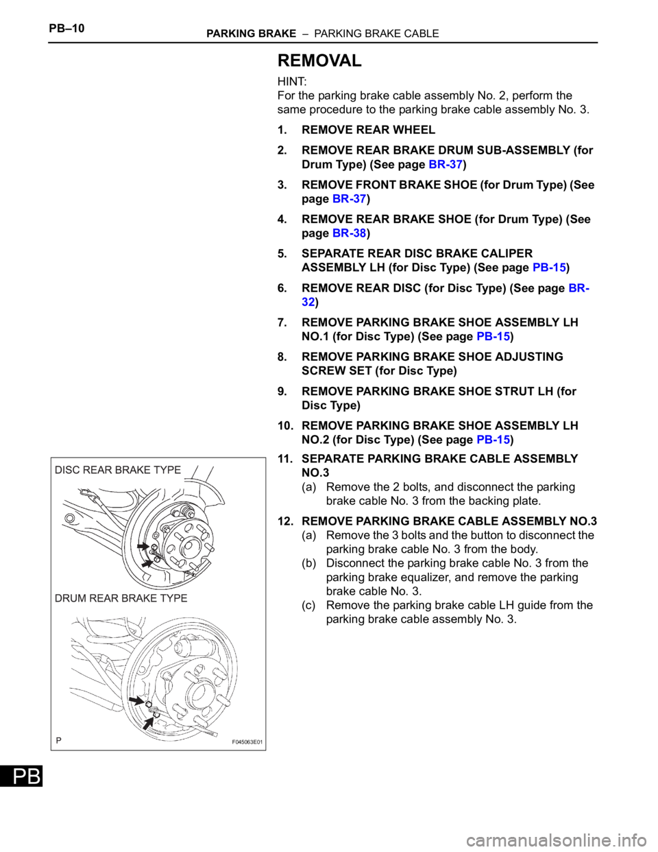
11. SEPARATE PARKING BRAKE CABLE ASSEMBLY
NO.3
(a) Remove the 2 bolts, and disconnect the parking
brake cable No. 3 from the backing plate.
12. REMOVE PARKING BRAKE CABLE ASSEMBLY NO.3
(a) Remove the 3 bolts and the button to disconnect the
parking brake cable No. 3 from the body.
(b) Disconnect the parking brake cable No. 3 from the
parking brake equalizer, and remove the parking
brake cable No. 3.
(c) Remove the parking brake cable LH guide from the
parking brake cable assembly No. 3.
F045063E01
Page 2675 of 3000
STEERING COLUMN – STEERING COLUMN ASSEMBLYSR–11
SR
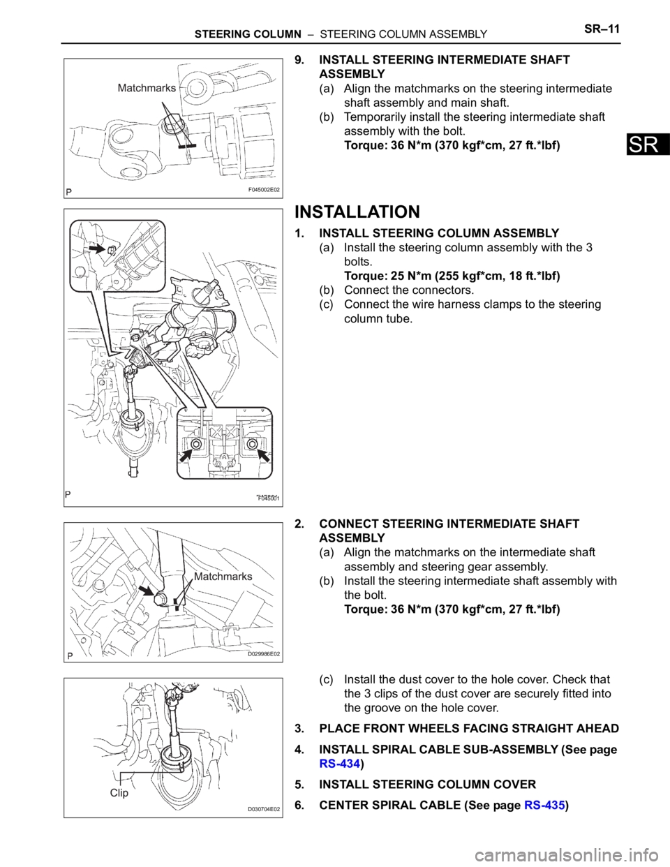
9. INSTALL STEERING INTERMEDIATE SHAFT
ASSEMBLY
(a) Align the matchmarks on the steering intermediate
shaft assembly and main shaft.
(b) Temporarily install the steering intermediate shaft
assembly with the bolt.
Torque: 36 N*m (370 kgf*cm, 27 ft.*lbf)
INSTALLATION
1. INSTALL STEERING COLUMN ASSEMBLY
(a) Install the steering column assembly with the 3
bolts.
Torque: 25 N*m (255 kgf*cm, 18 ft.*lbf)
(b) Connect the connectors.
(c) Connect the wire harness clamps to the steering
column tube.
2. CONNECT STEERING INTERMEDIATE SHAFT
ASSEMBLY
(a) Align the matchmarks on the intermediate shaft
assembly and steering gear assembly.
(b) Install the steering intermediate shaft assembly with
the bolt.
Torque: 36 N*m (370 kgf*cm, 27 ft.*lbf)
(c) Install the dust cover to the hole cover. Check that
the 3 clips of the dust cover are securely fitted into
the groove on the hole cover.
3. PLACE FRONT WHEELS FACING STRAIGHT AHEAD
4. INSTALL SPIRAL CABLE SUB-ASSEMBLY (See page
RS-434)
5. INSTALL STEERING COLUMN COVER
6. CENTER SPIRAL CABLE (See page RS-435)
F045002E02
F045001
D029986E02
D030704E02
Page 2684 of 3000
STEERING COLUMN – STEERING COLUMN ASSEMBLYSR–11
SR
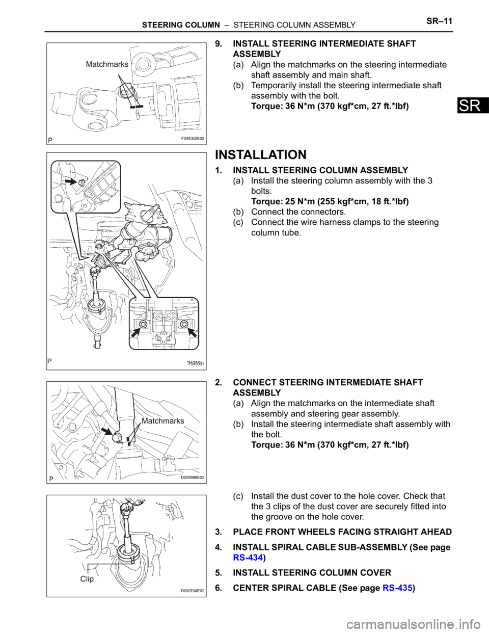
9. INSTALL STEERING INTERMEDIATE SHAFT
ASSEMBLY
(a) Align the matchmarks on the steering intermediate
shaft assembly and main shaft.
(b) Temporarily install the steering intermediate shaft
assembly with the bolt.
Torque: 36 N*m (370 kgf*cm, 27 ft.*lbf)
INSTALLATION
1. INSTALL STEERING COLUMN ASSEMBLY
(a) Install the steering column assembly with the 3
bolts.
Torque: 25 N*m (255 kgf*cm, 18 ft.*lbf)
(b) Connect the connectors.
(c) Connect the wire harness clamps to the steering
column tube.
2. CONNECT STEERING INTERMEDIATE SHAFT
ASSEMBLY
(a) Align the matchmarks on the intermediate shaft
assembly and steering gear assembly.
(b) Install the steering intermediate shaft assembly with
the bolt.
Torque: 36 N*m (370 kgf*cm, 27 ft.*lbf)
(c) Install the dust cover to the hole cover. Check that
the 3 clips of the dust cover are securely fitted into
the groove on the hole cover.
3. PLACE FRONT WHEELS FACING STRAIGHT AHEAD
4. INSTALL SPIRAL CABLE SUB-ASSEMBLY (See page
RS-434)
5. INSTALL STEERING COLUMN COVER
6. CENTER SPIRAL CABLE (See page RS-435)
F045002E02
F045001
D029986E02
D030704E02
Page 2709 of 3000
POWER STEERING – RACK AND PINION POWER STEERING GEARPS–41
PS
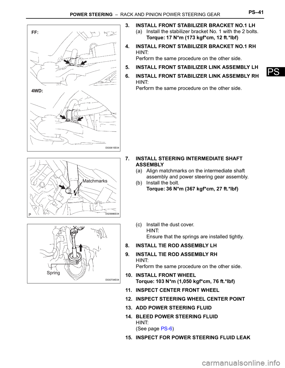
3. INSTALL FRONT STABILIZER BRACKET NO.1 LH
(a) Install the stabilizer bracket No. 1 with the 2 bolts.
Torque: 17 N*m (173 kgf*cm, 12 ft.*lbf)
4. INSTALL FRONT STABILIZER BRACKET NO.1 RH
HINT:
Perform the same procedure on the other side.
5. INSTALL FRONT STABILIZER LINK ASSEMBLY LH
6. INSTALL FRONT STABILIZER LINK ASSEMBLY RH
HINT:
Perform the same procedure on the other side.
7. INSTALL STEERING INTERMEDIATE SHAFT
ASSEMBLY
(a) Align matchmarks on the intermediate shaft
assembly and power steering gear assembly.
(b) Install the bolt.
Torque: 36 N*m (367 kgf*cm, 27 ft.*lbf)
(c) Install the dust cover.
HINT:
Ensure that the springs are installed tightly.
8. INSTALL TIE ROD ASSEMBLY LH
9. INSTALL TIE ROD ASSEMBLY RH
HINT:
Perform the same procedure on the other side.
10. INSTALL FRONT WHEEL
Torque: 103 N*m (1,050 kgf*cm, 76 ft.*lbf)
11. INSPECT CENTER FRONT WHEEL
12. INSPECT STEERING WHEEL CENTER POINT
13. ADD POWER STEERING FLUID
14. BLEED POWER STEERING FLUID
HINT:
(See page PS-6)
15. INSPECT FOR POWER STEERING FLUID LEAK
D030615E04
D029986E04
D030704E04