Page 2231 of 3000
SP–48SUSPENSION – REAR COIL SPRING
SP
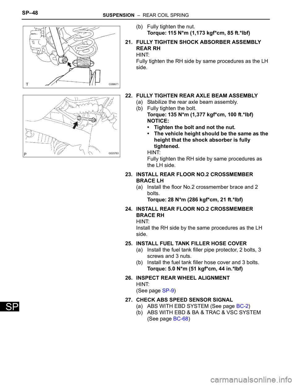
(b) Fully tighten the nut.
Torque: 115 N*m (1,173 kgf*cm, 85 ft.*lbf)
21. FULLY TIGHTEN SHOCK ABSORBER ASSEMBLY
REAR RH
HINT:
Fully tighten the RH side by same procedures as the LH
side.
22. FULLY TIGHTEN REAR AXLE BEAM ASSEMBLY
(a) Stabilize the rear axle beam assembly.
(b) Fully tighten the bolt.
Torque: 135 N*m (1,377 kgf*cm, 100 ft.*lbf)
NOTICE:
• Tighten the bolt and not the nut.
• The vehicle height should be the same as the
height that the shock absorber is fully
tightened.
HINT:
Fully tighten the RH side by same procedures as
the LH side.
23. INSTALL REAR FLOOR NO.2 CROSSMEMBER
BRACE LH
(a) Install the floor No.2 crossmember brace and 2
bolts.
Torque: 28 N*m (286 kgf*cm, 21 ft.*lbf)
24. INSTALL REAR FLOOR NO.2 CROSSMEMBER
BRACE RH
HINT:
Install the RH side by the same procedures as the LH
side.
25. INSTALL FUEL TANK FILLER HOSE COVER
(a) Install the fuel tank filler pipe protector, 2 bolts, 3
screws and 3 nuts.
(b) Install the fuel tank filler hose cover and 3 bolts.
Torque: 5.0 N*m (51 kgf*cm, 44 in.*lbf)
26. INSPECT REAR WHEEL ALIGNMENT
HINT:
(See page SP-9)
27. CHECK ABS SPEED SENSOR SIGNAL
(a) ABS WITH EBD SYSTEM (See page BC-2)
(b) ABS WITH EBD & BA & TRAC & VSC SYSTEM
(See page BC-68)
C088671
G025783
Page 2566 of 3000
BRAKE CONTROL – FRONT SPEED SENSORBC–187
BC
REMOVAL
HINT:
Remove the RH side by same procedures with LH side.
1. REMOVE FRONT WHEEL
2. REMOVE FRONT FENDER LINER LH
3. REMOVE FRONT SPEED SENSOR LH
(a) Disconnect the speed sensor connector.
(b) Remove the sensor harness and clamp from the
body.
(c) Remove the 2 clamp bolts holding the sensor
harness and clamp from the body and shock
absorber.
(d) Remove the bolt and speed sensor front LH.
NOTICE:
Keep the tip of the speed sensor front LH.
G024270
G024266
G024267
Page 2570 of 3000
BC–190BRAKE CONTROL – REAR SPEED SENSOR (for 2WD)
BC
REMOVAL
HINT:
Remove the RH by the same procedure as the LH side.
1. REMOVE REAR WHEEL
2. SEPARATE SKID CONTROL SENSOR WIRE
(a) Disconnect the connector from the skid control
sensor.
3. REMOVE REAR BRAKE DRUM SUB-ASSEMBLY (for
Drum Type)
(a) Place matchmarks on the rear brake drum sub-
assembly and the axle hub.
(b) Remove the rear brake drum sub-assembly.
4. REMOVE REAR DISC BRAKE CALIPER ASSEMBLY
LH (for Disc Type)
(a) Remove the 2 bolts and rear brake caliper assembly
LH.
5. REMOVE REAR DISC (for Disc Type)
(a) Place matchmarks on the rear disc and the axle
hub.
(b) Remove the rear disc.
6. REMOVE REAR AXLE HUB & BEARING ASSEMBLY
LH (See page AH-16)
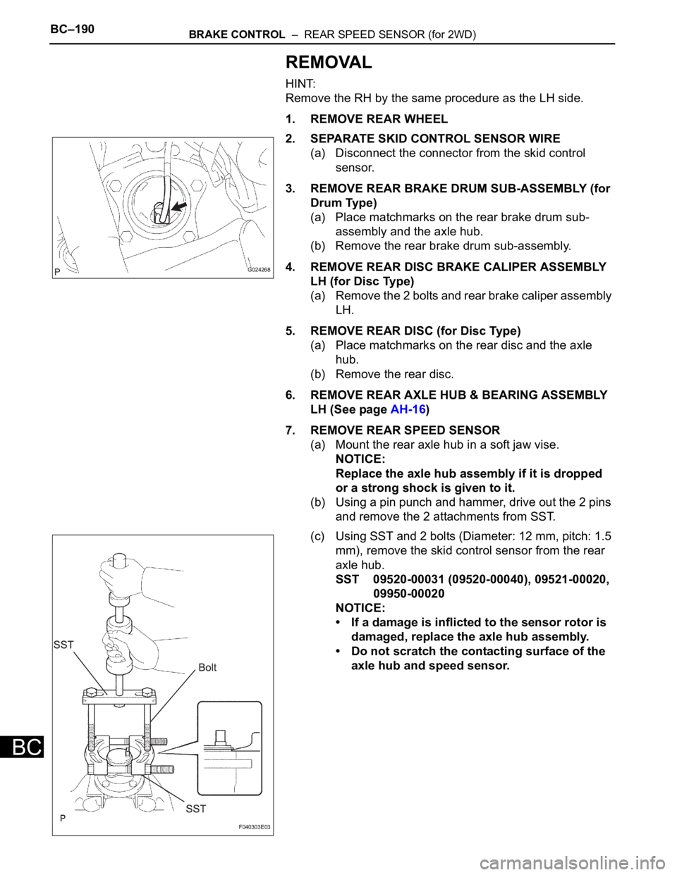
7. REMOVE REAR SPEED SENSOR
(a) Mount the rear axle hub in a soft jaw vise.
NOTICE:
Replace the axle hub assembly if it is dropped
or a strong shock is given to it.
(b) Using a pin punch and hammer, drive out the 2 pins
and remove the 2 attachments from SST.
(c) Using SST and 2 bolts (Diameter: 12 mm, pitch: 1.5
mm), remove the skid control sensor from the rear
axle hub.
SST 09520-00031 (09520-00040), 09521-00020,
09950-00020
NOTICE:
• If a damage is inflicted to the sensor rotor is
damaged, replace the axle hub assembly.
• Do not scratch the contacting surface of the
axle hub and speed sensor.
G024268
F040303E03
Page 2593 of 3000
BR–20BRAKE – BRAKE BOOSTER
BR
REMOVAL
NOTICE:
• Do not adjust the brake booster push rod.
• Do not change the combination of the diameter
converting unit and brake.
1. REMOVE FRONT WHEEL
2. DRAIN BRAKE FLUID
NOTICE:
Wash the brake fluid off immediately if it attaches to
any painted surfaces.
3. SEPARATE BATTERY NEGATIVE TERMINAL
4. REMOVE FRONT DOOR SCUFF PLATE LH
5. REMOVE COWL SIDE TRIM BOARD LH
(a) Remove the nut and cowl trim board plate LH.
6. REMOVE INSTRUMENT PANEL FINISH PANEL SUB-
ASSEMBLY LOWER LH
(a) Remove the 2 bolts and instrument panel finish
panel sub-assembly lower LH.
7. REMOVE INSTRUMENT PANEL SAFETY PAD
INSERT SUB-ASSEMBLY NO. 1
(a) Remove the 4 bolts and instrument panel safety pad
insert sub-assembly No. 1.
8. REMOVE COWL TOP PANEL SUB-ASSEMBLY
OUTER FRONT (See page SP-13)
9. REMOVE AIR CLEANER ASSEMBLY WITH HOSE
10. REMOVE BRAKE ACTUATOR ASSEMBLY (w/o VSC)
SST 09023-00101
HINT:
See page BC-184.
11. REMOVE ABS & TRACTION ACTUATOR ASSEMBLY
(w/ VSC)
SST 09023-00101
HINT:
See page BC-179.
12. REMOVE BRAKE LINE
(a) Remove the front brake tube No. 1, front brake tube
No. 2, front brake tube No. 3 and front brake tube
No. 4.
(b) Remove the rear brake tube No. 1 and rear brake
tube No. 2.
13. REMOVE PUSH ROD PIN
(a) Remove the push rod pin from the brake booster
push rod.
14. REMOVE BRAKE MASTER CYLINDER ASSEMBLY
(a) Slide the clip and disconnect the brake master
cylinder reservoir hose from the brake master
cylinder union.
Page 2602 of 3000
BR–24BRAKE – BRAKE BOOSTER
BR
15. INSTALL INSTRUMENT PANEL SAFETY PAD INSERT
SUB-ASSEMBLY NO. 1
(a) Install the instrument panel safety pad insert sub-
assembly No. 1 with the 4 bolts.
16. INSTALL INSTRUMENT PANEL FINISH PANEL SUB-
ASSEMBLY LOWER LH
(a) Install the instrument panel finish panel sub-
assembly lower LH with the 2 bolts.
17. INSTALL COWL SIDE TRIM BOARD LH
(a) Install the cowl trim board plate LH with the nut.
18. INSTALL FRONT DOOR SCUFF PLATE LH
19. INSTALL COWL TOP PANEL SUB-ASSEMBLY
OUTER FRONT
20. INSTALL FRONT WHEEL
Torque: 103 N*m (1,050 kgf*cm, 76 ft.*lbf)
21. INSPECT BRAKE PEDAL HEIGHT (See page BR-9)
22. CHECK BRAKE ACTUATOR WITH INTELLIGENT
TESTER
Type of Brake Actuator See Procedure
With VSCBC-178
Without VSCBC-183
Page 2617 of 3000
BRAKE – FRONT BRAKEBR–31
BR
7. REMOVE FRONT DISC BRAKE CYLINDER
ASSEMBLY LH
(a) Install the front disc brake cylinder sub-assembly
with the 2 bolts.
Torque: 34 N*m (350 kgf*cm, 25 ft.*lbf)
(b) Install a 2 new gaskets and flexible hose with the
union bolt.
Torque: 29 N*m (296 kgf*cm, 21 ft.*lbf)
HINT:
Install the flexible hose lock securely in the lock hole
in the disc brake cylinder.
8. FILL RESERVOIR WITH BRAKE FLUID (See page BR-
3)
9. BLEED BRAKE MASTER CYLINDER (See page BR-3)
10. BLEED BRAKE LINE (See page BR-4)
11. BLEED BRAKE ACTUATOR (w/ VSC) (See page BR-
4)
12. CHECK FLUID LEVEL IN RESERVOIR (See page BR-
7)
13. CHECK BRAKE FLUID LEAKAGE
14. INSTALL FRONT WHEEL
Torque: 103 N*m (1,050 kgf*cm, 76 ft.*lbf)
C097868
Page 2619 of 3000
BR–24BRAKE – FRONT BRAKE
BR
REMOVAL
HINT:
Remove the RH side by the same procedure as the LH side.
1. REMOVE FRONT WHEEL
2. DRAIN BRAKE FLUID
NOTICE:
Wash the brake fluid off immediately if it attaches to
any painted surface.
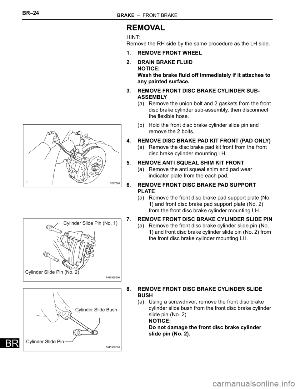
3. REMOVE FRONT DISC BRAKE CYLINDER SUB-
ASSEMBLY
(a) Remove the union bolt and 2 gaskets from the front
disc brake cylinder sub-assembly, then disconnect
the flexible hose.
(b) Hold the front disc brake cylinder slide pin and
remove the 2 bolts.
4. REMOVE DISC BRAKE PAD KIT FRONT (PAD ONLY)
(a) Remove the disc brake pad kit front from the front
disc brake cylinder mounting LH.
5. REMOVE ANTI SQUEAL SHIM KIT FRONT
(a) Remove the anti squeal shim and pad wear
indicator plate from the each pad.
6. REMOVE FRONT DISC BRAKE PAD SUPPORT
PLATE
(a) Remove the front disc brake pad support plate (No.
1) and front disc brake pad support plate (No. 2)
from the front disc brake cylinder mounting LH.
7. REMOVE FRONT DISC BRAKE CYLINDER SLIDE PIN
(a) Remove the front disc brake cylinder slide pin (No.
1) and front disc brake cylinder slide pin (No. 2) from
the front disc brake cylinder mounting LH.
8. REMOVE FRONT DISC BRAKE CYLINDER SLIDE
BUSH
(a) Using a screwdriver, remove the front disc brake
cylinder slide bush from the front disc brake cylinder
slide pin (No. 2).
NOTICE:
Do not damage the front disc brake cylinder
slide pin (No. 2).
C097868
F045565E06
F045566E03
Page 2628 of 3000
BRAKE – REAR DISC BRAKEBR–31
BR
REMOVAL
HINT:
Remove the RH side by the same procedure as the LH side.
1. REMOVE REAR WHEEL
2. DRAIN BRAKE FLUID
NOTICE:
Wash the brake fluid off immediately if it attaches to
any painted surface.
3. SEPARATE REAR BRAKE TUBE NO.4
(a) Remove the clip and a disconnect, the rear brake
flexible hose.
(b) Using SST and spanner loosen the rear brake tube
No. 4.
SST 09023-00101
4. SEPARATE REAR LH FLEXIBLE HOSE
(a) Using SST, remove the rear brake flexible hose.
SST 09023-12701
5. REMOVE DISC BRAKE CYLINDER ASSEMBLY REAR
LH
(a) Hold the rear disc brake cylinder slide pin and
remove the 2 bolts.
(b) Remove the disc brake cylinder assembly rear LH
from the rear disc brake cylinder mounting LH.
6. REMOVE REAR DISC BRAKE CYLINDER SLIDE PIN
(a) Remove the 2 rear disc brake cylinder slide pins
from the rear disc brake cylinder mounting LH.
7. REMOVE REAR DISC BRAKE BUSH DUST BOOT
(a) Remove the 2 rear disc brake bush dust boots.
8. REMOVE DISC BRAKE PAD KIT REAR (PAD ONLY)
(a) Remove the disc brake pad kit rear.
9. REMOVE REAR DISC BRAKE ANTI SQUEAL SHIM
KIT
(a) Remove the anti squeal shim No. 1 and anti squeal
shim No. 2 from each pad.
C065884
C090476
C085507