Page 2879 of 3000

AC–136AIR CONDITIONING – AIR CONDITIONING SYSTEM (for Automatic Air Conditioning Sys-
tem)
AC
B
A
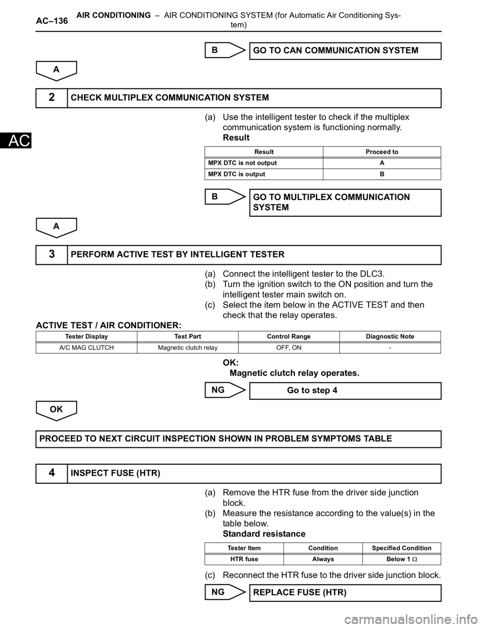
(a) Use the intelligent tester to check if the multiplex
communication system is functioning normally.
Result
B
A
(a) Connect the intelligent tester to the DLC3.
(b) Turn the ignition switch to the ON position and turn the
intelligent tester main switch on.
(c) Select the item below in the ACTIVE TEST and then
check that the relay operates.
ACTIVE TEST / AIR CONDITIONER:
OK:
Magnetic clutch relay operates.
NG
OK
(a) Remove the HTR fuse from the driver side junction
block.
(b) Measure the resistance according to the value(s) in the
table below.
Standard resistance
(c) Reconnect the HTR fuse to the driver side junction block.
NGGO TO CAN COMMUNICATION SYSTEM
2CHECK MULTIPLEX COMMUNICATION SYSTEM
Result Proceed to
MPX DTC is not output A
MPX DTC is output B
GO TO MULTIPLEX COMMUNICATION
SYSTEM
3PERFORM ACTIVE TEST BY INTELLIGENT TESTER
Tester Display Test Part Control Range Diagnostic Note
A/C MAG CLUTCH Magnetic clutch relay OFF, ON -
Go to step 4
PROCEED TO NEXT CIRCUIT INSPECTION SHOWN IN PROBLEM SYMPTOMS TABLE
4INSPECT FUSE (HTR)
Tester Item Condition Specified Condition
HTR fuse Always Below 1
REPLACE FUSE (HTR)
Page 2893 of 3000
AC–150AIR CONDITIONING – AIR CONDITIONING SYSTEM (for Automatic Air Conditioning Sys-
tem)
AC
DESCRIPTION
The main power source is supplied to the A/C amplifier when the ignition switch is turned to the ON
position.
The power source is used for operating the A/C amplifier and servo motor, etc.
WIRING DIAGRAM
INSPECTION PROCEDURE
HINT:
Start the engine before inspection. Check the IG1 relay or battery if the engine does not start.
(a) Remove the HTR fuse from the driver side junction
block.
(b) Measure the resistance according to the value(s) in the
table below.
Standard resistance
NG
IG Power Source Circuit
1INSPECT FUSE (HTR)
E130466E04
Tester Item Condition Specified Condition
HTR fuse Always Below 1
REPLACE FUSE (HTR)
Page 2896 of 3000
AIR CONDITIONING – AIR CONDITIONING SYSTEM (for Automatic Air Conditioning Sys-
tem)AC–153
AC
DESCRIPTION
This circuit supplies power to the A/C amplifier and the illumination for the clock.
WIRING DIAGRAM
INSPECTION PROCEDURE
(a) Remove the ECU ACC fuse from the engine room relay
block.
(b) Measure the resistance according to the value(s) in the
table below.
Standard resistance
NG
OK
ACC Power Source Circuit
1INSPECT FUSE (ECU ACC)
E146556E02
Tester Item Condition Specified Condition
ECU ACC Fuse Always Below 1
REPLACE FUSE (ECU ACC)
Page 2898 of 3000
AIR CONDITIONING – AIR CONDITIONING SYSTEM (for Automatic Air Conditioning Sys-
tem)AC–155
AC
DESCRIPTION
This is the back-up power source for the A/C amplifier. Power is supplied even when the ignition switch is
off and is used for diagnostic trouble code memory, etc.
WIRING DIAGRAM
INSPECTION PROCEDURE
(a) Remove the ECU-B fuse from the engine room junction
block.
(b) Measure the resistance according to the value(s) in the
table below.
Standard resistance
NG
OK
Back-up Power Source Circuit
1INSPECT FUSE (ECU-B)
E146556E03
Tester Item Condition Specified Condition
ECU-B Fuse Always Below 1
REPLACE FUSE (ECU-B)
Page 2904 of 3000

AIR CONDITIONING – AIR CONDITIONING SYSTEM (for Automatic Air Conditioning Sys-
tem)AC–15
AC
NOTICE:
*: Before measuring the resistance, leave the
vehicle as is for at least 1 minute and do not
operate the ignition switch, any other switches
or the doors.
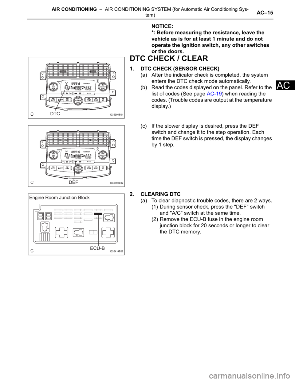
DTC CHECK / CLEAR
1. DTC CHECK (SENSOR CHECK)
(a) After the indicator check is completed, the system
enters the DTC check mode automatically.
(b) Read the codes displayed on the panel. Refer to the
list of codes (See page AC-19) when reading the
codes. (Trouble codes are output at the temperature
display.)
(c) If the slower display is desired, press the DEF
switch and change it to the step operation. Each
time the DEF switch is pressed, the display changes
by 1 step.
2. CLEARING DTC
(a) To clear diagnostic trouble codes, there are 2 ways.
(1) During sensor check, press the "DEF" switch
and "A/C" switch at the same time.
(2) Remove the ECU-B fuse in the engine room
junction block for 20 seconds or longer to clear
the DTC memory.
I035391E01
I035391E02
I035414E02