Page 611 of 3000
ES–3182GR-FE ENGINE CONTROL SYSTEM – SFI SYSTEM
ES
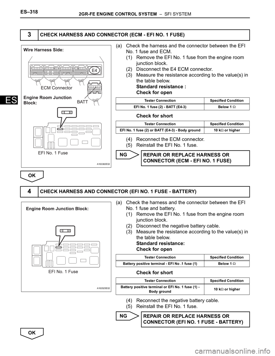
(a) Check the harness and the connector between the EFI
No. 1 fuse and ECM.
(1) Remove the EFI No. 1 fuse from the engine room
junction block.
(2) Disconnect the E4 ECM connector.
(3) Measure the resistance according to the value(s) in
the table below.
Standard resistance :
Check for open
Check for short
(4) Reconnect the ECM connector.
(5) Reinstall the EFI No. 1 fuse.
NG
OK
(a) Check the harness and the connector between the EFI
No. 1 fuse and battery.
(1) Remove the EFI No. 1 fuse from the engine room
junction block.
(2) Disconnect the negative battery cable.
(3) Measure the resistance according to the value(s) in
the table below.
Standard resistance:
Check for open
Check for short
(4) Reconnect the negative battery cable.
(5) Reinstall the EFI No. 1 fuse.
NG
OK
3CHECK HARNESS AND CONNECTOR (ECM - EFI NO. 1 FUSE)
A163382E02
Tester Connection Specified Condition
EFI No. 1 fuse (2) - BATT (E4-3) Below 1
Tester Connection Specified Condition
EFI No. 1 fuse (2) or BATT (E4-3) - Body ground 10 k
or higher
REPAIR OR REPLACE HARNESS OR
CONNECTOR (ECM - EFI NO. 1 FUSE)
4CHECK HARNESS AND CONNECTOR (EFI NO. 1 FUSE - BATTERY)
A163525E02
Tester Connection Specified Condition
Battery positive terminal - EFI No .1 fuse (1) Below 1
Tester Connection Specified Condition
Battery positive terminal or EFI No. 1 fuse (1) -
Body ground10 k
or higher
REPAIR OR REPLACE HARNESS OR
CONNECTOR (EFI NO. 1 FUSE - BATTERY)
Page 637 of 3000
ES–3442GR-FE ENGINE CONTROL SYSTEM – SFI SYSTEM
ES
DESCRIPTION
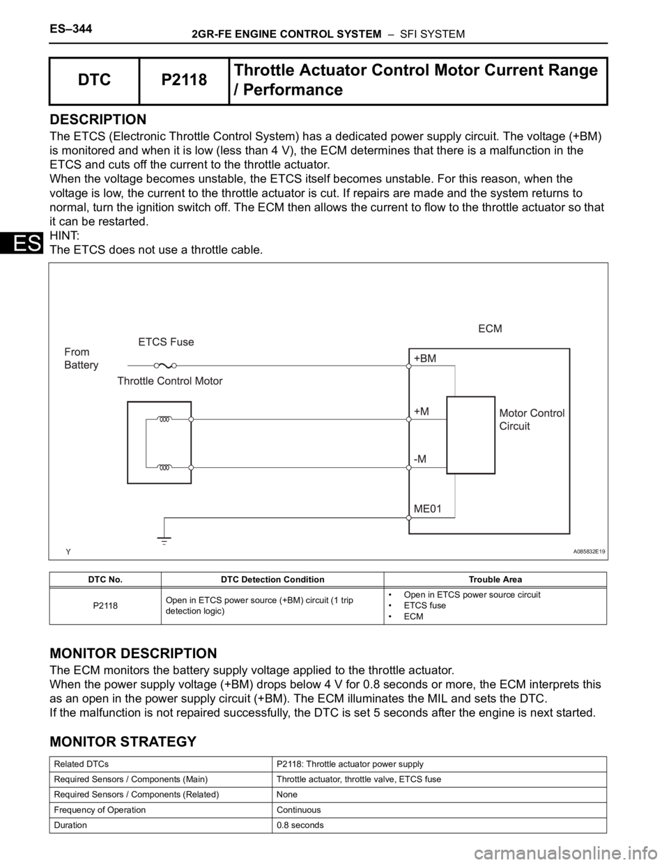
The ETCS (Electronic Throttle Control System) has a dedicated power supply circuit. The voltage (+BM)
is monitored and when it is low (less than 4 V), the ECM determines that there is a malfunction in the
ETCS and cuts off the current to the throttle actuator.
When the voltage becomes unstable, the ETCS itself becomes unstable. For this reason, when the
voltage is low, the current to the throttle actuator is cut. If repairs are made and the system returns to
normal, turn the ignition switch off. The ECM then allows the current to flow to the throttle actuator so that
it can be restarted.
HINT:
The ETCS does not use a throttle cable.
MONITOR DESCRIPTION
The ECM monitors the battery supply voltage applied to the throttle actuator.
When the power supply voltage (+BM) drops below 4 V for 0.8 seconds or more, the ECM interprets this
as an open in the power supply circuit (+BM). The ECM illuminates the MIL and sets the DTC.
If the malfunction is not repaired successfully, the DTC is set 5 seconds after the engine is next started.
MONITOR STRATEGY
DTC P2118Throttle Actuator Control Motor Current Range
/ Performance
DTC No. DTC Detection Condition Trouble Area
P2118Open in ETCS power source (+BM) circuit (1 trip
detection logic)• Open in ETCS power source circuit
• ETCS fuse
•ECM
Related DTCs P2118: Throttle actuator power supply
Required Sensors / Components (Main) Throttle actuator, throttle valve, ETCS fuse
Required Sensors / Components (Related) None
Frequency of Operation Continuous
Duration 0.8 seconds
A085832E19
Page 639 of 3000
ES–3462GR-FE ENGINE CONTROL SYSTEM – SFI SYSTEM
ES
INSPECTION PROCEDURE
HINT:
Read freeze frame data using the intelligent tester. The ECM records vehicle and driving condition
information as freeze frame data the moment a DTC is stored. When troubleshooting, freeze frame data
can be helpful in determining whether the vehicle was running or stopped, whether the engine was
warmed up or not, whether the air-fuel ratio was lean or rich, as well as other data recorded at the time of
a malfunction.
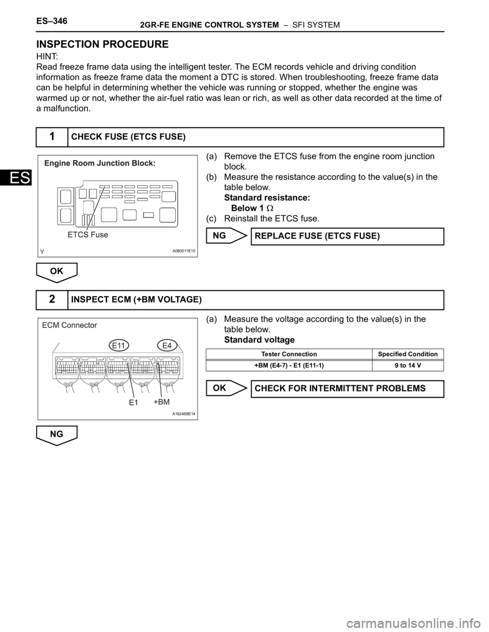
(a) Remove the ETCS fuse from the engine room junction
block.
(b) Measure the resistance according to the value(s) in the
table below.
Standard resistance:
Below 1
(c) Reinstall the ETCS fuse.
NG
OK
(a) Measure the voltage according to the value(s) in the
table below.
Standard voltage
OK
NG
1CHECK FUSE (ETCS FUSE)
A080011E10
REPLACE FUSE (ETCS FUSE)
2INSPECT ECM (+BM VOLTAGE)
A162489E14
Tester Connection Specified Condition
+BM (E4-7) - E1 (E11-1) 9 to 14 V
CHECK FOR INTERMITTENT PROBLEMS
Page 640 of 3000
2GR-FE ENGINE CONTROL SYSTEM – SFI SYSTEMES–347
ES
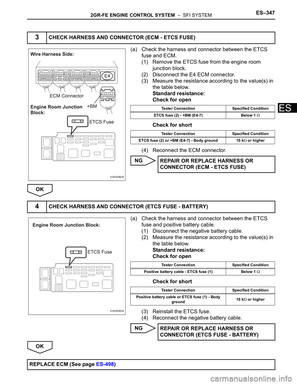
(a) Check the harness and connector between the ETCS
fuse and ECM.
(1) Remove the ETCS fuse from the engine room
junction block.
(2) Disconnect the E4 ECM connector.
(3) Measure the resistance according to the value(s) in
the table below.
Standard resistance:
Check for open
Check for short
(4) Reconnect the ECM connector.
NG
OK
(a) Check the harness and connector between the ETCS
fuse and positive battery cable.
(1) Disconnect the negative battery cable.
(2) Measure the resistance according to the value(s) in
the table below.
Standard resistance:
Check for open
Check for short
(3) Reinstall the ETCS fuse.
(4) Reconnect the negative battery cable.
NG
OK
3CHECK HARNESS AND CONNECTOR (ECM - ETCS FUSE)
A163528E02
Tester Connection Specified Condition
ETCS fuse (2) - +BM (E4-7) Below 1
Tester Connection Specified Condition
ETCS fuse (2) or +BM (E4-7) - Body ground 10 k
or higher
REPAIR OR REPLACE HARNESS OR
CONNECTOR (ECM - ETCS FUSE)
4CHECK HARNESS AND CONNECTOR (ETCS FUSE - BATTERY)
A163529E02
Tester Connection Specified Condition
Positive battery cable - ETCS fuse (1) Below 1
Tester Connection Specified Condition
Positive battery cable or ETCS fuse (1) - Body
ground10 k
or higher
REPAIR OR REPLACE HARNESS OR
CONNECTOR (ETCS FUSE - BATTERY)
REPLACE ECM (See page ES-498)
Page 733 of 3000
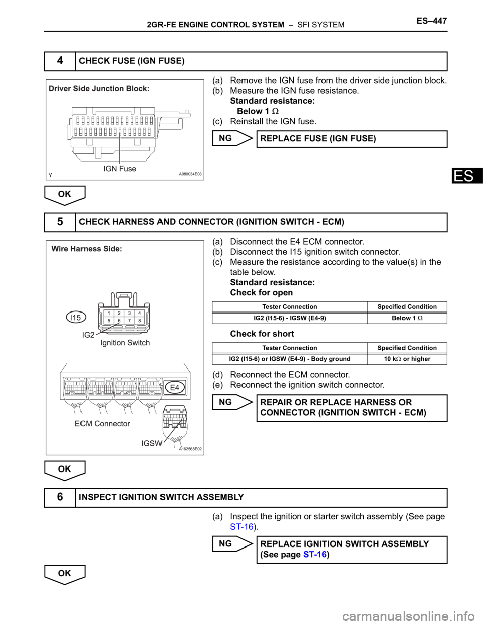
2GR-FE ENGINE CONTROL SYSTEM – SFI SYSTEMES–447
ES
(a) Remove the IGN fuse from the driver side junction block.
(b) Measure the IGN fuse resistance.
Standard resistance:
Below 1
(c) Reinstall the IGN fuse.
NG
OK
(a) Disconnect the E4 ECM connector.
(b) Disconnect the I15 ignition switch connector.
(c) Measure the resistance according to the value(s) in the
table below.
Standard resistance:
Check for open
Check for short
(d) Reconnect the ECM connector.
(e) Reconnect the ignition switch connector.
NG
OK
(a) Inspect the ignition or starter switch assembly (See page
ST-16).
NG
OK
4CHECK FUSE (IGN FUSE)
A080034E03
REPLACE FUSE (IGN FUSE)
5CHECK HARNESS AND CONNECTOR (IGNITION SWITCH - ECM)
A162568E02
Tester Connection Specified Condition
IG2 (I15-6) - IGSW (E4-9) Below 1
Tester Connection Specified Condition
IG2 (I15-6) or IGSW (E4-9) - Body ground 10 k
or higher
REPAIR OR REPLACE HARNESS OR
CONNECTOR (IGNITION SWITCH - ECM)
6INSPECT IGNITION SWITCH ASSEMBLY
REPLACE IGNITION SWITCH ASSEMBLY
(See page ST-16)
Page 734 of 3000
ES–4482GR-FE ENGINE CONTROL SYSTEM – SFI SYSTEM
ES
(a) Remove the AM2 fuse from the engine room junction
block.
(b) Measure the resistance according to the value(s) in the
table below.
Standard resistance:
Below 1
(c) Reinstall the AM2 fuse
NG
OK
(a) Turn the ignition switch to the ON position.
(b) Measure the voltage according to the value(s) in the
table below.
Standard voltage
NG
OK
(a) Remove the EFI No. 1 fuse from the engine room
junction block.
(b) Measure the EFI No. 1 fuse resistance.
Standard resistance:
Below 1
(c) Reinstall the EFI No. 1 fuse.
NG
OK
7CHECK FUSE (AM2 FUSE)
A080011E11
REPLACE FUSE (AM2 FUSE)
REPAIR OR REPLACE HARNESS OR CONNECTOR (IGNITION SWITCH - BATTERY)
8INSPECT ECM (MREL VOLTAGE)
A162489E11
Tester Connection Specified Condition
MREL (E4-8) - E1 (E11-1) 9 to 14 V
REPLACE ECM (See page ES-498)
9CHECK FUSE (EFI NO.1 FUSE)
A080011E09
REPLACE FUSE (EFI NO.1 FUSE)
Page 748 of 3000
ES–4622GR-FE ENGINE CONTROL SYSTEM – SFI SYSTEM
ES
NG
(a) Disconnect the E4 ECM connector.
(b) Remove the C/OPN relay from the engine room junction
block.
(c) Measure the resistance according to the value(s) in the
table below.
Standard resistance:
Check for open
Check for short
(d) Reconnect the ECM connector.
(e) Reinstall the C/OPN relay.
NG
OK
(a) Remove the IGN fuse from the driver side junction block.
(b) Measure the resistance according to the value(s) in the
table below.
Standard resistance:
Below 1
(c) Reinstall the IGN fuse.
NG
OK
5CHECK HARNESS AND CONNECTOR (ECM - C/OPN RELAY)
A163319E02
Tester Connection Specified Condition
FC (E4-10) - C/OPN terminal (1) Below 1
Tester Connection Specified Condition
FC (E4-10) or C/OPN terminal (1) - Body ground 10 k
or higher
REPAIR OR REPLACE HARNESS OR
CONNECTOR (ECM - C/OPN RELAY)
6CHECK FUSE (IGN FUSE)
A080034E04
REPLACE FUSE (IGN FUSE)
Page 762 of 3000
ES–4762GR-FE ENGINE CONTROL SYSTEM – SFI SYSTEM
ES
(a) Remove the ST fuse from the fuse box.
(b) Measure the resistance according to the value(s) in the
table below.
Standard resistance
(c) Reinstall the ST fuse.
NG
OK
(a) Disconnect the I15 ignition switch connector.
(b) Measure the resistance according to the value(s) in the
table below.
Standard resistance
(c) Reconnect the ignition switch connector.
NG
OK
13INSPECT FUSE (ST FUSE)
A166723E01
Tester Connection Specified Condition
1 - 2 Below 1
REPLACE FUSE (ST FUSE)
14INSPECT IGNITION SWITCH ASSEMBLY
B050489E19
Switch Condition Tester Connection Specified Condition
LOCK All terminals 10 k
or higher
ACC 1 - 3 Below 1
ON 1 - 2, 1 - 3, 2 - 3, 5 - 6 Below 1
START 4 - 5, 4 - 6, 5 - 6, 1 - 2 Below 1
REPLACE IGNITION SWITCH ASSEMBLY