2007 TOYOTA SIENNA relay
[x] Cancel search: relayPage 428 of 3000
ES–1222GR-FE ENGINE CONTROL SYSTEM – SFI SYSTEM
ES
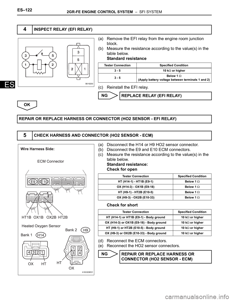
(a) Remove the EFI relay from the engine room junction
block.
(b) Measure the resistance according to the value(s) in the
table below.
Standard resistance
(c) Reinstall the EFI relay.
NG
OK
(a) Disconnect the H14 or H9 HO2 sensor connector.
(b) Disconnect the E9 and E10 ECM connectors.
(c) Measure the resistance according to the value(s) in the
table below.
Standard resistance:
Check for open
Check for short
(d) Reconnect the ECM connectors.
(e) Reconnect the HO2 sensor connectors.
NG
4INSPECT RELAY (EFI RELAY)
B016200
Tester Connection Specified Condition
3 - 5 10 k
or higher
3 - 5Below 1
(Apply battery voltage between terminals 1 and 2)
REPLACE RELAY (EFI RELAY)
REPAIR OR REPLACE HARNESS OR CONNECTOR (HO2 SENSOR - EFI RELAY)
5CHECK HARNESS AND CONNECTOR (HO2 SENSOR - ECM)
A163309E01
Tester Connection Specified Condition
HT (H14-1) - HT1B (E9-1) Below 1
OX (H14-3) - OX1B (E9-18) Below 1
HT (H9-1) - HT2B (E10-5) Below 1
OX (H9-3) - OX2B (E10-33) Below 1
Tester Connection Specified Condition
HT (H14-1) or HT1B (E9-1) - Body ground 10 k
or higher
OX (H14-3) or OX1B (E9-18) - Body ground 10 k
or higher
HT (H9-1) or HT2B (E10-5) - Body ground 10 k
or higher
OX (H9-3) or OX2B (E10-33) - Body ground 10 k
or higher
REPAIR OR REPLACE HARNESS OR
CONNECTOR (HO2 SENSOR - ECM)
Page 434 of 3000
ES–1282GR-FE ENGINE CONTROL SYSTEM – SFI SYSTEM
ES
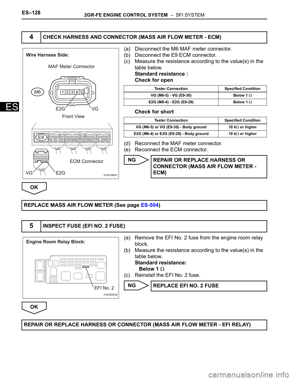
(a) Disconnect the M6 MAF meter connector.
(b) Disconnect the E9 ECM connector.
(c) Measure the resistance according to the value(s) in the
table below.
Standard resistance :
Check for open
Check for short
(d) Reconnect the MAF meter connector.
(e) Reconnect the ECM connector.
NG
OK
(a) Remove the EFI No. 2 fuse from the engine room relay
block.
(b) Measure the resistance according to the value(s) in the
table below.
Standard resistance:
Below 1
(c) Reinstall the EFI No. 2 fuse.
NG
OK
4CHECK HARNESS AND CONNECTOR (MASS AIR FLOW METER - ECM)
A140709E07
Tester Connection Specified Condition
VG (M6-5) - VG (E9-30) Below 1
E2G (M6-4) - E2G (E9-29) Below 1
Tester Connection Specified Condition
VG (M6-5) or VG (E9-30) - Body ground 10 k
or higher
E2G (M6-4) or E2G (E9-29) - Body ground 10 k
or higher
REPAIR OR REPLACE HARNESS OR
CONNECTOR (MASS AIR FLOW METER -
ECM)
REPLACE MASS AIR FLOW METER (See page ES-504)
5INSPECT FUSE (EFI NO. 2 FUSE)
A162360E09
REPLACE EFI NO. 2 FUSE
REPAIR OR REPLACE HARNESS OR CONNECTOR (MASS AIR FLOW METER - EFI RELAY)
Page 475 of 3000
2GR-FE ENGINE CONTROL SYSTEM – SFI SYSTEMES–169
ES
MONITOR DESCRIPTION
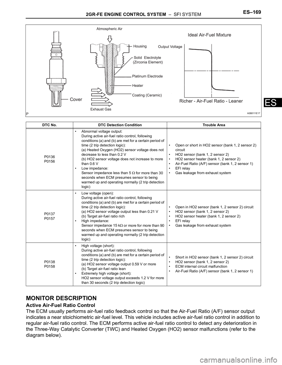
Active Air-Fuel Ratio Control
The ECM usually performs air-fuel ratio feedback control so that the Air-Fuel Ratio (A/F) sensor output
indicates a near stoichiometric air-fuel level. This vehicle includes active air-fuel ratio control in addition to
regular air-fuel ratio control. The ECM performs active air-fuel ratio control to detect any deterioration in
the Three-Way Catalytic Converter (TWC) and Heated Oxygen (HO2) sensor malfunctions (refer to the
diagram below).
DTC No. DTC Detection Condition Trouble Area
P0136
P0156• Abnormal voltage output:
During active air-fuel ratio control, following
conditions (a) and (b) are met for a certain period of
time (2 trip detection logic):
(a) Heated Oxygen (HO2) sensor voltage does not
decrease to less than 0.2 V
(b) HO2 sensor voltage does not increase to more
than 0.6 V
• Low impedance:
Sensor impedance less than 5
for more than 30
seconds when ECM presumes sensor to being
warmed up and operating normally (2 trip detection
logic)• Open or short in HO2 sensor (bank 1, 2 sensor 2)
circuit
• HO2 sensor (bank 1, 2 sensor 2)
• HO2 sensor heater (bank 1, 2 sensor 2)
• Air-Fuel Ratio (A/F) sensor (bank 1, 2 sensor 1)
• EFI relay
• Gas leakage from exhaust system
P0137
P0157• Low voltage (open):
During active air-fuel ratio control, following
conditions (a) and (b) are met for a certain period of
time (2 trip detection logic):
(a) HO2 sensor voltage output less than 0.21 V
(b) Target air-fuel ratio rich
• High impedance:
Sensor impedance 15 k
or more for more than 90
seconds when ECM presumes sensor to being
warmed up and operating normally (2 trip detection
logic)• Open in HO2 sensor (bank 1, 2 sensor 2) circuit
• HO2 sensor (bank 1, 2 sensor 2)
• HO2 sensor heater (bank 1, 2 sensor 2)
• EFI relay
• Gas leakage from exhaust system
P0138
P0158• High voltage (short):
During active air-fuel ratio control, following
conditions (a) and (b) are met for a certain period of
time (2 trip detection logic):
(a) HO2 sensor voltage output 0.59 V or more
(b) Target air-fuel ratio lean
• Extremely high voltage (short):
HO2 sensor voltage output exceeds 1.2 V for more
than 30 seconds (2 trip detection logic)• Short in HO2 sensor (bank 1, 2 sensor 2) circuit
• HO2 sensor (bank 1, 2 sensor 2)
• ECM internal circuit malfunction
• Air-Fuel Ratio (A/F) sensor (bank 1, 2 sensor 1)
A 0 8 8 111 E 1 7
Page 491 of 3000
2GR-FE ENGINE CONTROL SYSTEM – SFI SYSTEMES–185
ES
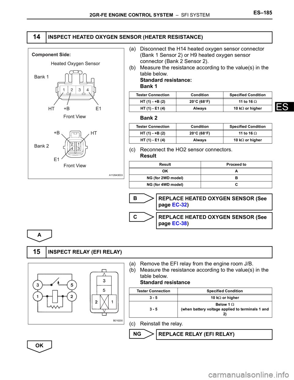
(a) Disconnect the H14 heated oxygen sensor connector
(Bank 1 Sensor 2) or H9 heated oxygen sensor
connector (Bank 2 Sensor 2).
(b) Measure the resistance according to the value(s) in the
table below.
Standard resistance:
Bank 1
Bank 2
(c) Reconnect the HO2 sensor connectors.
Result
B
C
A
(a) Remove the EFI relay from the engine room J/B.
(b) Measure the resistance according to the value(s) in the
table below.
Standard resistance
(c) Reinstall the relay.
NG
OK
14INSPECT HEATED OXYGEN SENSOR (HEATER RESISTANCE)
A112643E03
Tester Connection Condition Specified Condition
HT (1) - +B (2) 20
C (68F) 11 to 16
HT (1) - E1 (4) Always 10 k or higher
Tester Connection Condition Specified Condition
HT (1) - +B (2) 20
C (68F) 11 to 16
HT (1) - E1 (4) Always 10 k or higher
Result Proceed to
OK A
NG (for 2WD model) B
NG (for 4WD model) C
REPLACE HEATED OXYGEN SENSOR (See
page EC-32)
REPLACE HEATED OXYGEN SENSOR (See
page EC-38)
15INSPECT RELAY (EFI RELAY)
B016200
Tester Connection Specified Condition
3 - 5 10 k
or higher
3 - 5Below 1
(when battery voltage applied to terminals 1 and
2)
REPLACE RELAY (EFI RELAY)
Page 494 of 3000

ES–1882GR-FE ENGINE CONTROL SYSTEM – SFI SYSTEM
ES
DESCRIPTION
The fuel trim is related to the feedback compensation value, not to the basic injection time. The fuel trim
consists of both the short-term and long-term fuel trims.
The short-term fuel trim is fuel compensation that is used to constantly maintain the air-fuel ratio at
stoichiometric levels. The signal from the Air-Fuel Ratio (A/F) sensor indicates whether the air-fuel ratio is
rich or lean compared to the stoichiometric ratio. This triggers a reduction in the fuel injection volume if the
air-fuel ratio is rich and an increase in the fuel injection volume if it is lean.
Factors such as individual engine differences, wear over time and changes in operating environment
cause short-term fuel trim to vary from the central value. The long-term fuel trim, which controls overall
fuel compensation, compensates for long-term deviations in the fuel trim from the central value caused by
the short-term fuel trim compensation.
If both the short-term and long-term fuel trims are lean or rich beyond predetermined values, it is
interpreted as a malfunction, and the ECM illuminates the MIL and sets a DTC.
HINT:
• When DTC P0171 or P0174 is set, the actual air-fuel ratio is on the lean side. When DTC P0172 or
P0175 is set, the actual air-fuel ratio is on the rich side.
• If the vehicle runs out of fuel, the air-fuel ratio is lean and DTC P0171 or P0174 may be set. The MIL is
then illuminated.
DTC P0171 System Too Lean (Bank 1)
DTC P0172 System Too Rich (Bank 1)
DTC P0174 System Too Lean (Bank 2)
DTC P0175 System Too Rich (Bank 2)
DTC No. DTC Detection Condition Trouble Area
P0171
P0174With warm engine and stable air-fuel ratio feedback,
fuel trim considerably in error to lean side (2 trip
detection logic)• Intake system
• Injector blockage
• Mass Air Flow (MAF) meter
• Engine Coolant Temperature (ECT) sensor
• Fuel pressure
• Gas leakage from exhaust system
• Open or short in A/F sensor (bank 1, 2 sensor 1)
circuit
• A/F sensor (bank 1, 2 sensor 1)
• A/F sensor heater (bank 1, 2 sensor 1)
• A/F sensor heater relay
• A/F sensor heater and A/F sensor heater relay
circuits
• PCV valve and hose
• PCV hose connections
•ECM
P0172
P0175With warm engine and stable air-fuel ratio feedback,
fuel trim considerably in error to rich side (2 trip
detection logic)• Injector leakage or blockage
• MAF meter
• ECT sensor
• Ignition system
• Fuel pressure
• Gas leakage from exhaust system
• Open or short in A/F sensor (bank 1, 2 sensor 1)
circuit
• A/F sensor (bank 1, 2 sensor 1)
• A/F sensor heater (bank 1, 2 sensor 1)
• A/F sensor heater relay
• A/F sensor heater and A/F sensor heater relay
circuits
•ECM
Page 502 of 3000
ES–1962GR-FE ENGINE CONTROL SYSTEM – SFI SYSTEM
ES
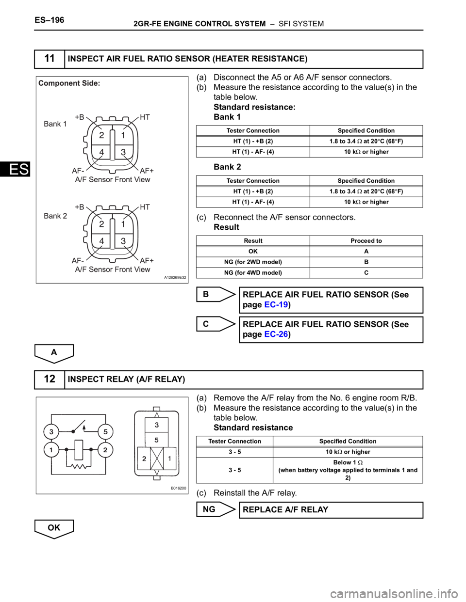
(a) Disconnect the A5 or A6 A/F sensor connectors.
(b) Measure the resistance according to the value(s) in the
table below.
Standard resistance:
Bank 1
Bank 2
(c) Reconnect the A/F sensor connectors.
Result
B
C
A
(a) Remove the A/F relay from the No. 6 engine room R/B.
(b) Measure the resistance according to the value(s) in the
table below.
Standard resistance
(c) Reinstall the A/F relay.
NG
OK
11INSPECT AIR FUEL RATIO SENSOR (HEATER RESISTANCE)
A126269E32
Tester Connection Specified Condition
HT (1) - +B (2) 1.8 to 3.4
at 20C (68F)
HT (1) - AF- (4) 10 k
or higher
Tester Connection Specified Condition
HT (1) - +B (2) 1.8 to 3.4
at 20C (68F)
HT (1) - AF- (4) 10 k
or higher
Result Proceed to
OK A
NG (for 2WD model) B
NG (for 4WD model) C
REPLACE AIR FUEL RATIO SENSOR (See
page EC-19)
REPLACE AIR FUEL RATIO SENSOR (See
page EC-26)
12INSPECT RELAY (A/F RELAY)
B016200
Tester Connection Specified Condition
3 - 5 10 k
or higher
3 - 5Below 1
(when battery voltage applied to terminals 1 and
2)
REPLACE A/F RELAY
Page 506 of 3000

ES–2002GR-FE ENGINE CONTROL SYSTEM – SFI SYSTEM
ES
DESCRIPTION
• This DTC is designed to detect a malfunction in the fuel pump (FUEL PUMP) relay circuit. When the
system is normal, the battery voltage is applied to FPR terminal of the ECM while the FUEL PUMP
relay is turned OFF. If the battery voltage is not applied to the FPR terminal while the FUEL PUMP
relay is OFF, the ECM interprets this as a malfunction. The ECM then illuminates the MIL and sets a
DTC.
• The FUEL PUMP relay switches the fuel pump speed according to the engine conditions. The fuel
pump operates when the ECM receives the starter-operating signal (STA) and crankshaft-rotating
signal (NE). The FUEL PUMP relay is turned ON while the engine is idling or operating at low load.
This causes current to flow through the fuel pump resistor to the fuel pump. The fuel pump then
operates at low speed. The FUEL PUMP relay is turned OFF while the engine is cranking or operating
at high load. The fuel pump then operates at normal speed.
DTC P0230 Fuel Pump Primary Circuit
DTC No. DTC Detection Condition Trouble Area
P0230Open or short in FUEL PUMP relay circuit (1 trip
detection logic)• Open or short in FUEL PUMP relay circuit
• FUEL PUMP relay
•ECM
Page 508 of 3000
ES–2022GR-FE ENGINE CONTROL SYSTEM – SFI SYSTEM
ES
(b) Turn the ignition switch to the ON position and turn the
intelligent tester ON.
(c) Enter the following menus: DIAGNOSIS / ENHANCED
OBD II / ACTIVE TEST / FUEL PUMP SP CTL.
(d) Check the operation of the relay while operating it using
the intelligent tester.
OK:
Operating noise can be heard from the relay.
OK
NG
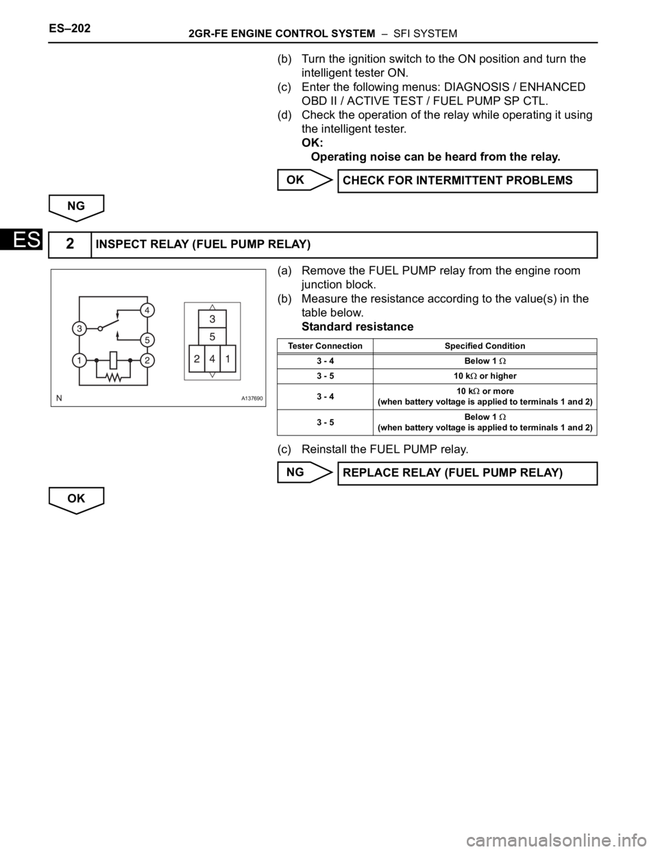
(a) Remove the FUEL PUMP relay from the engine room
junction block.
(b) Measure the resistance according to the value(s) in the
table below.
Standard resistance
(c) Reinstall the FUEL PUMP relay.
NG
OKCHECK FOR INTERMITTENT PROBLEMS
2INSPECT RELAY (FUEL PUMP RELAY)
A137690
Tester Connection Specified Condition
3 - 4 Below 1
3 - 5 10 k or higher
3 - 410 k
or more
(when battery voltage is applied to terminals 1 and 2)
3 - 5Below 1
(when battery voltage is applied to terminals 1 and 2)
REPLACE RELAY (FUEL PUMP RELAY)