Page 748 of 3000
ES–4622GR-FE ENGINE CONTROL SYSTEM – SFI SYSTEM
ES
NG
(a) Disconnect the E4 ECM connector.
(b) Remove the C/OPN relay from the engine room junction
block.
(c) Measure the resistance according to the value(s) in the
table below.
Standard resistance:
Check for open
Check for short
(d) Reconnect the ECM connector.
(e) Reinstall the C/OPN relay.
NG
OK
(a) Remove the IGN fuse from the driver side junction block.
(b) Measure the resistance according to the value(s) in the
table below.
Standard resistance:
Below 1
(c) Reinstall the IGN fuse.
NG
OK
5CHECK HARNESS AND CONNECTOR (ECM - C/OPN RELAY)
A163319E02
Tester Connection Specified Condition
FC (E4-10) - C/OPN terminal (1) Below 1
Tester Connection Specified Condition
FC (E4-10) or C/OPN terminal (1) - Body ground 10 k
or higher
REPAIR OR REPLACE HARNESS OR
CONNECTOR (ECM - C/OPN RELAY)
6CHECK FUSE (IGN FUSE)
A080034E04
REPLACE FUSE (IGN FUSE)
Page 749 of 3000

2GR-FE ENGINE CONTROL SYSTEM – SFI SYSTEMES–463
ES
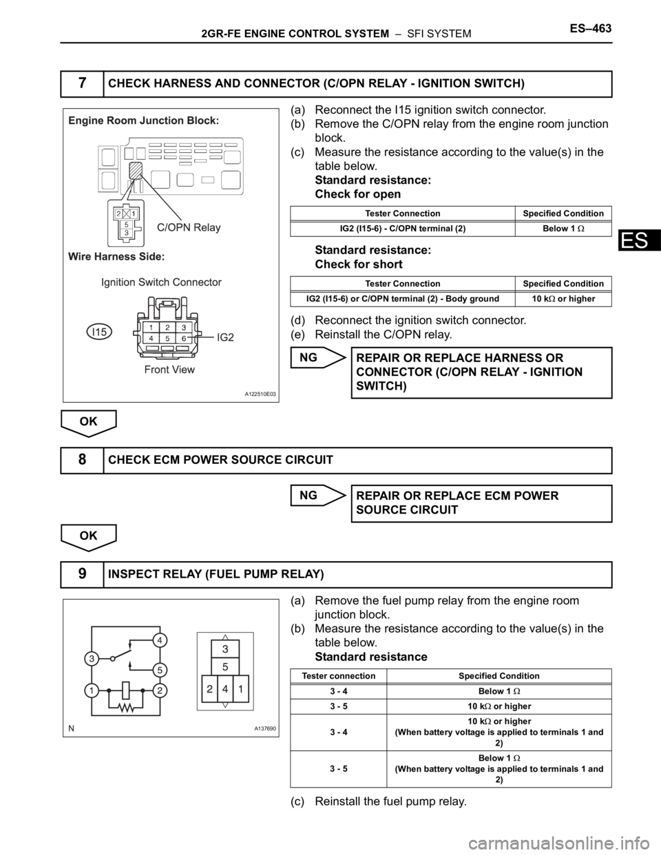
(a) Reconnect the I15 ignition switch connector.
(b) Remove the C/OPN relay from the engine room junction
block.
(c) Measure the resistance according to the value(s) in the
table below.
Standard resistance:
Check for open
Standard resistance:
Check for short
(d) Reconnect the ignition switch connector.
(e) Reinstall the C/OPN relay.
NG
OK
NG
OK
(a) Remove the fuel pump relay from the engine room
junction block.
(b) Measure the resistance according to the value(s) in the
table below.
Standard resistance
(c) Reinstall the fuel pump relay.
7CHECK HARNESS AND CONNECTOR (C/OPN RELAY - IGNITION SWITCH)
A122510E03
Tester Connection Specified Condition
IG2 (I15-6) - C/OPN terminal (2) Below 1
Tester Connection Specified Condition
IG2 (I15-6) or C/OPN terminal (2) - Body ground 10 k
or higher
REPAIR OR REPLACE HARNESS OR
CONNECTOR (C/OPN RELAY - IGNITION
SWITCH)
8CHECK ECM POWER SOURCE CIRCUIT
REPAIR OR REPLACE ECM POWER
SOURCE CIRCUIT
9INSPECT RELAY (FUEL PUMP RELAY)
A137690
Tester connection Specified Condition
3 - 4 Below 1
3 - 5 10 k or higher
3 - 410 k
or higher
(When battery voltage is applied to terminals 1 and
2)
3 - 5Below 1
(When battery voltage is applied to terminals 1 and
2)
Page 750 of 3000
ES–4642GR-FE ENGINE CONTROL SYSTEM – SFI SYSTEM
ES
NG
OK
(a) Measure the resistance of the fuel pump.
(1) Measure the resistance according to the value(s) in
the table below.
Standard resistance
(b) Check operation of the fuel pump.
(1) Apply battery voltage to both terminals. Check that
the pump operates.
NOTICE:
• These tests must be done quickly (within 10
seconds) to prevent the coil from burning
out.
• Keep the fuel pump as far away from the
battery as possible.
• Always turn ON and OFF the voltage on the
battery side, not on the fuel pump side.
NG
OKREPLACE RELAY (FUEL PUMP RELAY)
10INSPECT FUEL PUMP
A074356E31
Tester Connection Condition Specified Condition
4 - 5 20
C (68F) 0.2 to 0.3
REPLACE FUEL PUMP ASSEMBLY (See
page FU-30)
Page 751 of 3000

2GR-FE ENGINE CONTROL SYSTEM – SFI SYSTEMES–465
ES
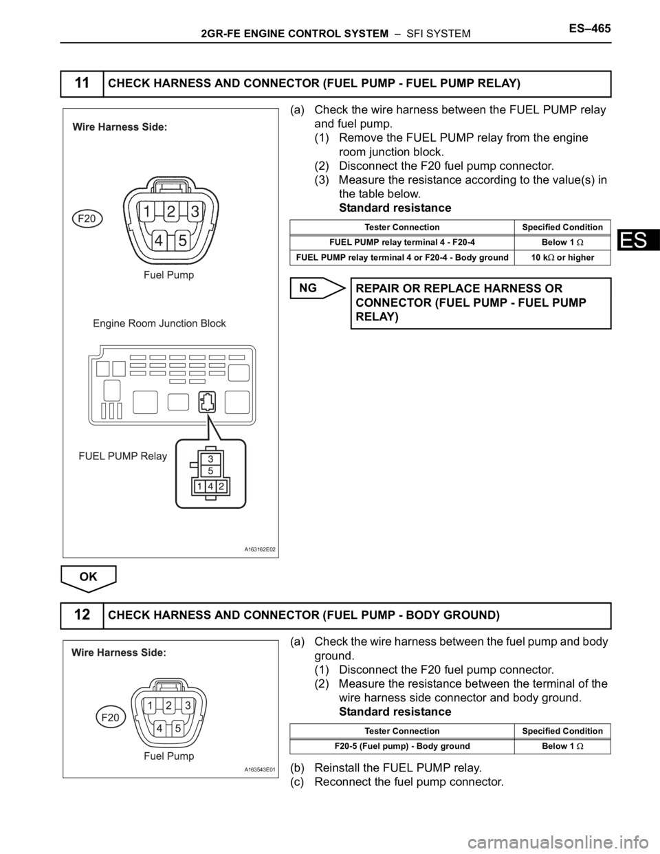
(a) Check the wire harness between the FUEL PUMP relay
and fuel pump.
(1) Remove the FUEL PUMP relay from the engine
room junction block.
(2) Disconnect the F20 fuel pump connector.
(3) Measure the resistance according to the value(s) in
the table below.
Standard resistance
NG
OK
(a) Check the wire harness between the fuel pump and body
ground.
(1) Disconnect the F20 fuel pump connector.
(2) Measure the resistance between the terminal of the
wire harness side connector and body ground.
Standard resistance
(b) Reinstall the FUEL PUMP relay.
(c) Reconnect the fuel pump connector.
11CHECK HARNESS AND CONNECTOR (FUEL PUMP - FUEL PUMP RELAY)
A163162E02
Tester Connection Specified Condition
FUEL PUMP relay terminal 4 - F20-4 Below 1
FUEL PUMP relay terminal 4 or F20-4 - Body ground 10 k or higher
REPAIR OR REPLACE HARNESS OR
CONNECTOR (FUEL PUMP - FUEL PUMP
RELAY)
12CHECK HARNESS AND CONNECTOR (FUEL PUMP - BODY GROUND)
A163543E01
Tester Connection Specified Condition
F20-5 (Fuel pump) - Body ground Below 1
Page 752 of 3000

ES–4662GR-FE ENGINE CONTROL SYSTEM – SFI SYSTEM
ES
NG
OK
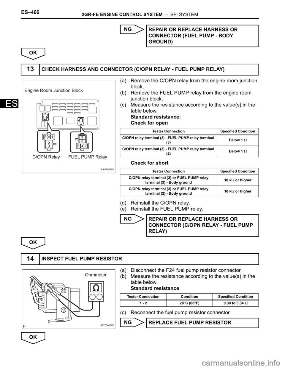
(a) Remove the C/OPN relay from the engine room junction
block.
(b) Remove the FUEL PUMP relay from the engine room
junction block.
(c) Measure the resistance according to the value(s) in the
table below.
Standard resistance:
Check for open
Check for short
(d) Reinstall the C/OPN relay.
(e) Reinstall the FUEL PUMP relay.
NG
OK
(a) Disconnect the F24 fuel pump resistor connector.
(b) Measure the resistance according to the value(s) in the
table below.
Standard resistance
(c) Reconnect the fuel pump resistor connector.
NG
OKREPAIR OR REPLACE HARNESS OR
CONNECTOR (FUEL PUMP - BODY
GROUND)
13CHECK HARNESS AND CONNECTOR (C/OPN RELAY - FUEL PUMP RELAY)
A163320E02
Tester Connection Specified Condition
C/OPN relay terminal (3) - FUEL PUMP relay terminal
(3)Below 1
C/OPN relay terminal (3) - FUEL PUMP relay terminal
(2)Below 1
Tester Connection Specified Condition
C/OPN relay terminal (3) or FUEL PUMP relay
terminal (3) - Body ground10 k
or higher
C/OPN relay terminal (3) or FUEL PUMP relay
terminal (2) - Body ground10 k
or higher
REPAIR OR REPLACE HARNESS OR
CONNECTOR (C/OPN RELAY - FUEL PUMP
RELAY)
14INSPECT FUEL PUMP RESISTOR
A072544E01
Tester Connection Condition Specified Condition
1 - 2 20
C (68F) 0.30 to 0.34
REPLACE FUEL PUMP RESISTOR
Page 753 of 3000
2GR-FE ENGINE CONTROL SYSTEM – SFI SYSTEMES–467
ES
(a) Disconnect the F24 fuel pump resistor connector.
(b) Remove the FUEL PUMP relay from the engine room
junction block.
(c) Measure the resistance according to the value(s) in the
table below.
Standard resistance:
Check for open
Check for short
(d) Reconnect the fuel pump resistor connector.
(e) Reinstall the FUEL PUMP relay.
NG
OK
15CHECK HARNESS AND CONNECTOR (FUEL PUMP RELAY - FUEL PUMP RESISTOR)
A163163E02
Tester Connection Specified Condition
FUEL PUMP relay terminal (4) - F24-2 Below 1
FUEL PUMP relay terminal (5) - F24-1 Below 1
Tester Connection Specified Condition
FUEL PUMP relay terminal (4) or F24-2 - Body
ground10 k
or higher
FUEL PUMP relay terminal (5) or F24-1 - Body
ground10 k
or higher
REPAIR OR REPLACE HARNESS OR
CONNECTOR (FUEL PUMP RELAY - FUEL
PUMP RESISTOR)
Page 758 of 3000

ES–4722GR-FE ENGINE CONTROL SYSTEM – SFI SYSTEM
ES
OK
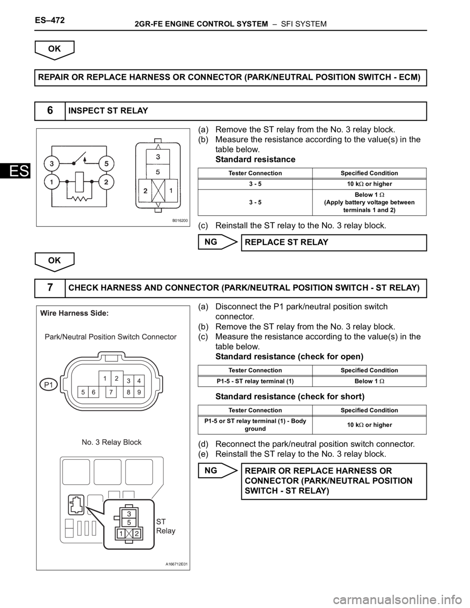
(a) Remove the ST relay from the No. 3 relay block.
(b) Measure the resistance according to the value(s) in the
table below.
Standard resistance
(c) Reinstall the ST relay to the No. 3 relay block.
NG
OK
(a) Disconnect the P1 park/neutral position switch
connector.
(b) Remove the ST relay from the No. 3 relay block.
(c) Measure the resistance according to the value(s) in the
table below.
Standard resistance (check for open)
Standard resistance (check for short)
(d) Reconnect the park/neutral position switch connector.
(e) Reinstall the ST relay to the No. 3 relay block.
NG REPAIR OR REPLACE HARNESS OR CONNECTOR (PARK/NEUTRAL POSITION SWITCH - ECM)
6INSPECT ST RELAY
B016200
Tester Connection Specified Condition
3 - 5 10 k
or higher
3 - 5Below 1
(Apply battery voltage between
terminals 1 and 2)
REPLACE ST RELAY
7CHECK HARNESS AND CONNECTOR (PARK/NEUTRAL POSITION SWITCH - ST RELAY)
A166712E01
Tester Connection Specified Condition
P1-5 - ST relay terminal (1) Below 1
Tester Connection Specified Condition
P1-5 or ST relay terminal (1) - Body
ground10 k
or higher
REPAIR OR REPLACE HARNESS OR
CONNECTOR (PARK/NEUTRAL POSITION
SWITCH - ST RELAY)
Page 759 of 3000
2GR-FE ENGINE CONTROL SYSTEM – SFI SYSTEMES–473
ES
OK
(a) Remove the ST relay from the No. 3 relay block.
(b) Measure the resistance according to the value(s) in the
table below.
Standard resistance
(c) Reinstall the ST relay to the No. 3 relay block.
NG
OK
(a) Remove the ST relay from the No. 3 relay block.
(b) Measure the voltage according to the value(s) in the
table below.
Standard voltage
(c) Reinstall the ST relay to the No. 3 relay block.
OK
NG
8CHECK HARNESS AND CONNECTOR (ST RELAY - BODY GROUND)
A166709E01
Tester Connection Specified Condition
ST relay terminal (2) - Body ground Below 1
REPAIR OR REPLACE HARNESS OR
CONNECTOR (ST RELAY - BODY GROUND)
9CHECK ST RELAY (POWER SOURCE)
A166709E01
Tester Connection Specified Condition
ST relay terminal (5) - Body ground 9 to 14 V
Go to step 11