Page 674 of 3000

2GR-FE ENGINE CONTROL SYSTEM – SFI SYSTEMES–381
ESHINT:
• DTC P2238, P2239, P2252 and P2253 indicate malfunctions related to the bank 1 A/F sensor circuit.
• DTC P2241, P2242, P2255 and P2256 indicate malfunctions related to the bank 2 A/F sensor circuit.
• Bank 1 refers to the bank that includes cylinder No. 1.
• Bank 2 refers to the bank that includes cylinder No. 2.
MONITOR DESCRIPTION
The Air-Fuel Ratio (A/F) sensor varies its output voltage in proportion to the air-fuel ratio. If the A/F sensor
impedance (alternating current resistance) or voltage output deviates greatly from the standard range, the
ECM determines that there is an open or short malfunction in the A/F sensor circuit.
MONITOR STRATEGY
TYPICAL ENABLING CONDITIONS
All:
P2238 and P2241 (open circuit between AF+ and AF-):
P2252
P2255AF-voltage is 0.5 V or less for 5.0 seconds or more (2
trip detection logic)• Open or short in A/F sensor (bank 1, 2 sensor 1)
circuit
• A/F sensor (bank 1, 2 sensor 1)
• A/F sensor heater
• A/F sensor heater relay
• A/F sensor heater and relay circuits
•ECM
P2253
P2256AF-voltage is more than 4.5 V for 5.0 seconds or more
(2 trip detection logic)• Open or short in A/F sensor (bank 1, 2 sensor 1)
circuit
• A/F sensor (bank 1, 2 sensor 1)
• A/F sensor heater
• A/F sensor heater relay
• A/F sensor heater and relay circuits
•ECM
Related DTCsP2238: A/F sensor (Bank 1) open circuit between AF+ and AF-
P2238: A/F sensor (Bank 1) short circuit between AF+ and AF-
P2238: A/F sensor (Bank 1) short circuit between AF+ and GND
P2239: A/F sensor (Bank 1) short circuit between AF+ and +B
P2241: A/F sensor (Bank 2) open circuit between AF+ and AF-
P2241: A/F sensor (Bank 2) short circuit between AF+ and AF-
P2241: A/F sensor (Bank 2) short circuit between AF+ and GND
P2242: A/F sensor (Bank 2) short circuit between AF+ and +B
P2252: A/F sensor (Bank 1) short circuit between AF- and GND
P2253: A/F sensor (Bank 1) short circuit between AF- and +B
P2255: A/F sensor (Bank 2) short circuit between AF- and GND
P2256: A/F sensor (Bank 2) short circuit between AF- and +B
Required Sensors / Components (Main) A/F sensor
Required Sensors / Components (Related) Engine Coolant Temperature (ECT) sensor, Crankshaft position sensor
Frequency of Operation Once per driving cycle
DurationP2238 and P2241 (open circuit between AF+ and AF-): 10 seconds
Others: 5 seconds
MIL Operation 2 driving cycles
Sequence of Operation None
The monitor will run whenever these DTCs are not
presentNone
AF+ terminal voltage 0.5 to 4.5 V
AF- terminal voltage 0.5 to 4.5 V
Difference between AF+ terminal and AF- terminal
voltage0.1 to 0.8 V
ECT 5
C (41F) or more (varies with ECT at engine start) DTC No. DTC Detection Condition Trouble Area
Page 678 of 3000
2GR-FE ENGINE CONTROL SYSTEM – SFI SYSTEMES–385
ES
B
C
A
(a) Remove the A/F relay from the No. 6 engine room relay
block.
(b) Measure the resistance according to the value(s) in the
table below.
Standard resistance
(c) Reinstall the A/F relay.
NG
OKREPLACE AIR FUEL RATIO SENSOR (See
page EC-19)
REPLACE AIR FUEL RATIO SENSOR (See
page EC-26)
2INSPECT RELAY (A/F RELAY)
B016200
Tester Connection Specified Condition
3 - 5 10 k
or higher
3 - 5Below 1
(when battery voltage applied to terminals 1 and
2)
REPLACE RELAY (A/F RELAY)
Page 731 of 3000
2GR-FE ENGINE CONTROL SYSTEM – SFI SYSTEMES–445
ES
DESCRIPTION
When the ignition switch is turned to the ON position, the battery voltage is applied to terminal IGSW of
the ECM. The ECM MREL output signal causes a current to flow to the coil, closing the contacts of the EFI
relay and supplying power to terminal +B of the ECM.
If the ignition switch is turned off, the ECM holds the EFI relay ON for a maximum of 2 seconds to allow for
the initial setting of the throttle valve.
WIRING DIAGRAM
ECM Power Source Circuit
A136865E04
Page 735 of 3000

2GR-FE ENGINE CONTROL SYSTEM – SFI SYSTEMES–449
ES
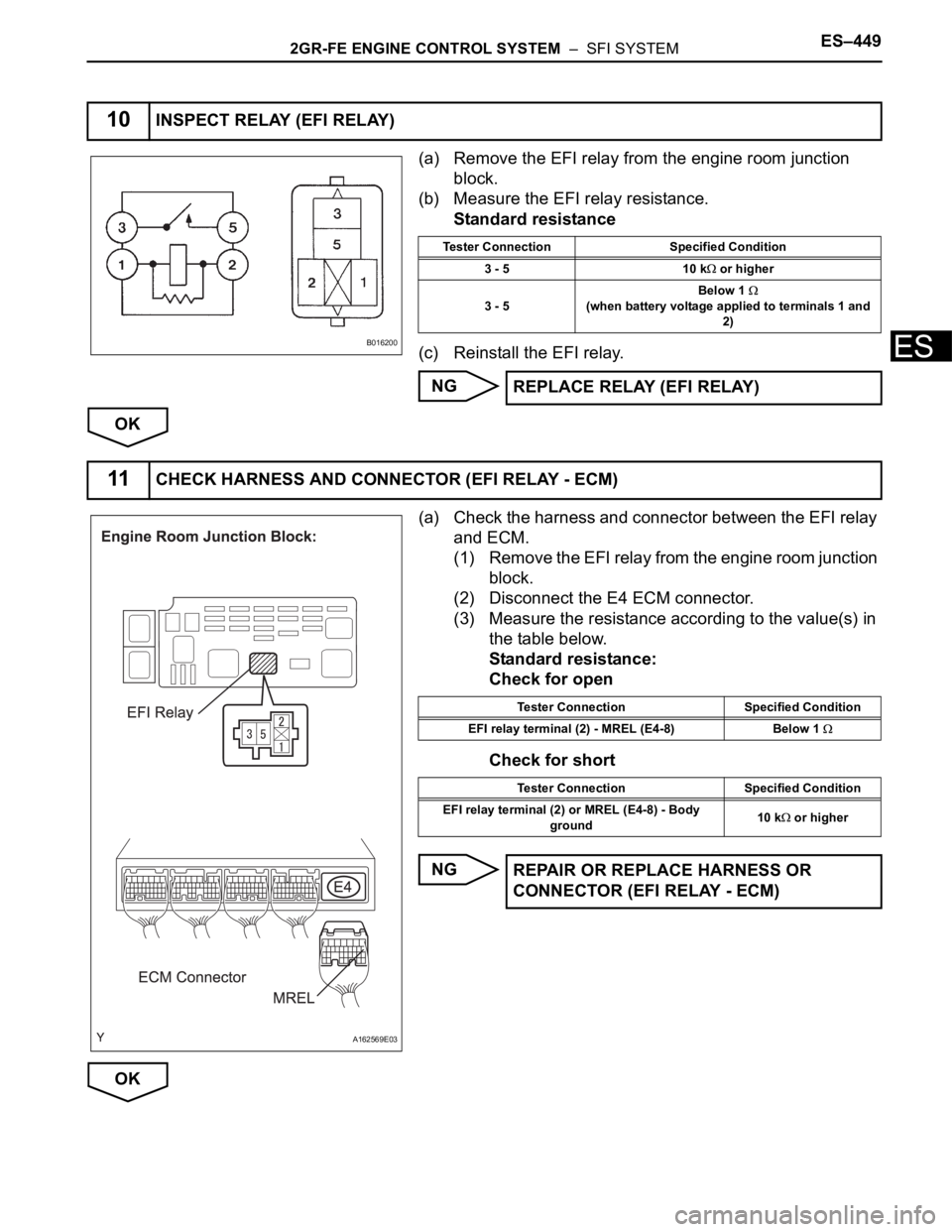
(a) Remove the EFI relay from the engine room junction
block.
(b) Measure the EFI relay resistance.
Standard resistance
(c) Reinstall the EFI relay.
NG
OK
(a) Check the harness and connector between the EFI relay
and ECM.
(1) Remove the EFI relay from the engine room junction
block.
(2) Disconnect the E4 ECM connector.
(3) Measure the resistance according to the value(s) in
the table below.
Standard resistance:
Check for open
Check for short
NG
OK
10INSPECT RELAY (EFI RELAY)
B016200
Tester Connection Specified Condition
3 - 5 10 k
or higher
3 - 5Below 1
(when battery voltage applied to terminals 1 and
2)
REPLACE RELAY (EFI RELAY)
11CHECK HARNESS AND CONNECTOR (EFI RELAY - ECM)
A162569E03
Tester Connection Specified Condition
EFI relay terminal (2) - MREL (E4-8) Below 1
Tester Connection Specified Condition
EFI relay terminal (2) or MREL (E4-8) - Body
ground10 k
or higher
REPAIR OR REPLACE HARNESS OR
CONNECTOR (EFI RELAY - ECM)
Page 736 of 3000

ES–4502GR-FE ENGINE CONTROL SYSTEM – SFI SYSTEM
ES
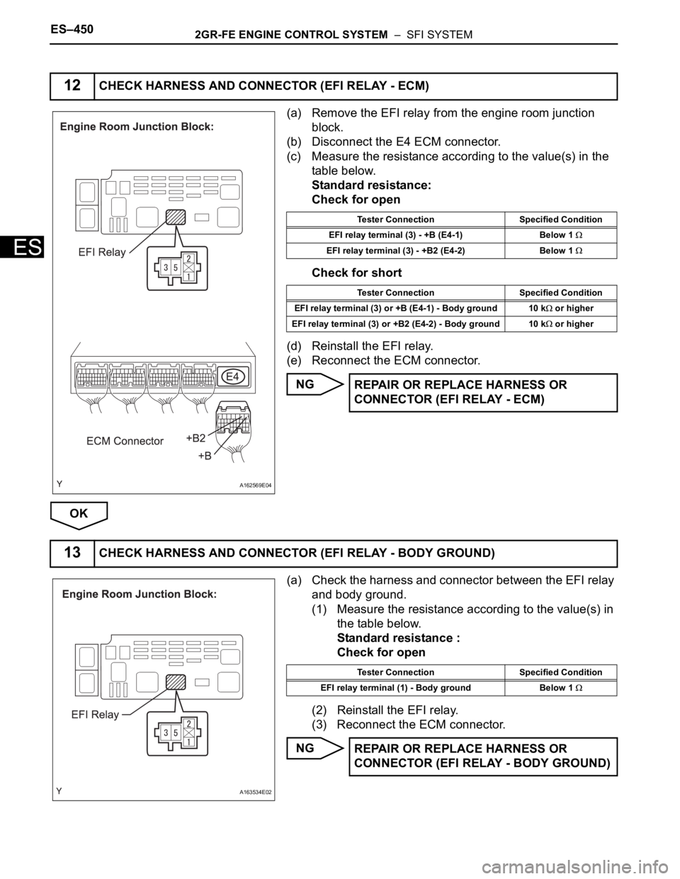
(a) Remove the EFI relay from the engine room junction
block.
(b) Disconnect the E4 ECM connector.
(c) Measure the resistance according to the value(s) in the
table below.
Standard resistance:
Check for open
Check for short
(d) Reinstall the EFI relay.
(e) Reconnect the ECM connector.
NG
OK
(a) Check the harness and connector between the EFI relay
and body ground.
(1) Measure the resistance according to the value(s) in
the table below.
Standard resistance :
Check for open
(2) Reinstall the EFI relay.
(3) Reconnect the ECM connector.
NG
12CHECK HARNESS AND CONNECTOR (EFI RELAY - ECM)
A162569E04
Tester Connection Specified Condition
EFI relay terminal (3) - +B (E4-1) Below 1
EFI relay terminal (3) - +B2 (E4-2) Below 1
Tester Connection Specified Condition
EFI relay terminal (3) or +B (E4-1) - Body ground 10 k
or higher
EFI relay terminal (3) or +B2 (E4-2) - Body ground 10 k
or higher
REPAIR OR REPLACE HARNESS OR
CONNECTOR (EFI RELAY - ECM)
13CHECK HARNESS AND CONNECTOR (EFI RELAY - BODY GROUND)
A163534E02
Tester Connection Specified Condition
EFI relay terminal (1) - Body ground Below 1
REPAIR OR REPLACE HARNESS OR
CONNECTOR (EFI RELAY - BODY GROUND)
Page 737 of 3000
2GR-FE ENGINE CONTROL SYSTEM – SFI SYSTEMES–451
ES
OK
REPAIR OR REPLACE HARNESS OR CONNECTOR (EFI RELAY - BATTERY)
Page 745 of 3000
2GR-FE ENGINE CONTROL SYSTEM – SFI SYSTEMES–459
ES
DESCRIPTION
The FUEL PUMP relay switches the fuel pump speed according to the engine conditions. The fuel pump
operates when the ECM receives the starter-operating signal (STA) and crankshaft-rotating signal (NE).
The FUEL PUMP relay is turned ON while the engine is idling or operating at low load. This causes
current to flow through the fuel pump resistor to the fuel pump. The fuel pump then operates at low speed.
The FUEL PUMP relay is turned OFF while the engine is cranking or operating at high load. The fuel
pump then operates at normal speed.
Fuel Pump Control Circuit
A165826E01
Page 747 of 3000

2GR-FE ENGINE CONTROL SYSTEM – SFI SYSTEMES–461
ES
OK
NG
(a) Connect the intelligent tester to the DLC3.
(b) Turn the ignition switch to the ON position and turn the
intelligent tester or the OBD II scan tool main switch on.
(c) Enter the following menus: DIAGNOSIS / ENHANCED
OBD II / ACTIVE TEST / FUEL PUMP / SPD.
(d) Check the relay operation while operating it using the
intelligent tester.
Standard:
Operating noise can be heard from the relay.
OK
NG
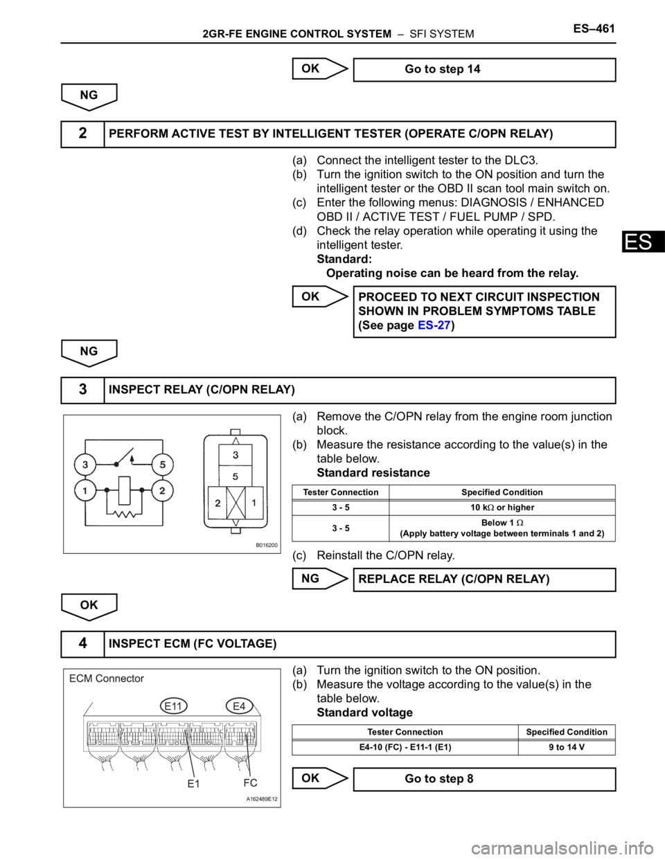
(a) Remove the C/OPN relay from the engine room junction
block.
(b) Measure the resistance according to the value(s) in the
table below.
Standard resistance
(c) Reinstall the C/OPN relay.
NG
OK
(a) Turn the ignition switch to the ON position.
(b) Measure the voltage according to the value(s) in the
table below.
Standard voltage
OK Go to step 14
2PERFORM ACTIVE TEST BY INTELLIGENT TESTER (OPERATE C/OPN RELAY)
PROCEED TO NEXT CIRCUIT INSPECTION
SHOWN IN PROBLEM SYMPTOMS TABLE
(See page ES-27)
3INSPECT RELAY (C/OPN RELAY)
B016200
Tester Connection Specified Condition
3 - 5 10 k
or higher
3 - 5Below 1
(Apply battery voltage between terminals 1 and 2)
REPLACE RELAY (C/OPN RELAY)
4INSPECT ECM (FC VOLTAGE)
A162489E12
Tester Connection Specified Condition
E4-10 (FC) - E11-1 (E1) 9 to 14 V
Go to step 8