Page 760 of 3000
ES–4742GR-FE ENGINE CONTROL SYSTEM – SFI SYSTEM
ES
(a) Remove the fusible link block from the engine room
junction block.
(b) Measure the resistance according to the value(s) in the
table below.
Standard resistance
(c) Reinstall the fusible link block to the engine room
junction block.
NG
OK
(a) Inspect the starter assembly (See page ST-7).
NG
OK
10INSPECT FUSIBLE LINK
A166720E02
Tester Connection Specified Condition
Fusible link Below 1
REPLACE FUSIBLE LINK
REPAIR OR REPLACE HARNESS OR CONNECTOR (BATTERY - STARTER RELAY)
11INSPECT STARTER ASSEMBLY
REPLACE STARTER ASSEMBLY
Page 761 of 3000
2GR-FE ENGINE CONTROL SYSTEM – SFI SYSTEMES–475
ES
(a) Remove the ST relay from the No. 3 relay block.
(b) Disconnect the S4 starter connector.
(c) Measure the resistance according to the value(s) in the
table below.
Standard resistance (check for open)
Standard resistance (check for short)
(d) Reconnect the starter connector.
(e) Reinstall the ST relay to the No. 3 relay block.
NG
OK
12CHECK HARNESS AND CONNECTOR (ST RELAY - STARTER ASSEMBLY)
A166713E01
Tester Connection Specified Condition
ST relay terminal (3) - S4-1 Below 1
Tester Connection Specified Condition
ST relay terminal (3) or S4-1 - Body
ground10 k
or higher
REPAIR OR REPLACE HARNESS OR
CONNECTOR (ST RELAY - STARTER
ASSEMBLY)
REPAIR OR REPLACE HARNESS OR CONNECTOR (BATTERY - STARTER ASSEMBLY)
Page 767 of 3000
2GR-FE ENGINE CONTROL SYSTEM – SFI SYSTEMES–481
ES
(a) Check the wire harness between the VSV for ACIS
connector and EFI relay.
(1) Remove the EFI relay from the engine room junction
block.
(2) Disconnect the V14 VSV connector.
(3) Measure the resistance according to the value(s) in
the table below.
Standard resistance :
Check for open
(4) Reinstall the EFI relay.
(5) Reconnect the VSV connector.
NG
OK
5CHECK HARNESS AND CONNECTOR (VSV FOR ACIS - EFI RELAY)
A163545E04
Tester Connection Specified Condition
VSV for ACIS (V14-2) - EFI relay terminal (3) Below 1
REPAIR OR REPLACE HARNESS OR
CONNECTOR (VSV FOR ACIS - EFI RELAY)
CHECK ECM POWER SOURCE CIRCUIT (See page ES-437)
Page 809 of 3000

2GR-FE ENGINE CONTROL SYSTEM – SFI SYSTEMES–31
ES
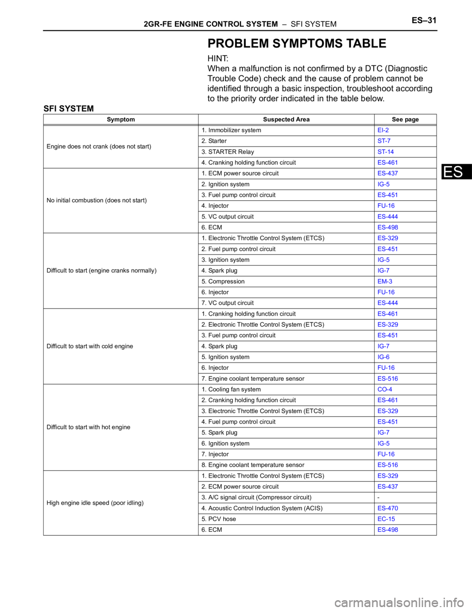
PROBLEM SYMPTOMS TABLE
HINT:
When a malfunction is not confirmed by a DTC (Diagnostic
Trouble Code) check and the cause of problem cannot be
identified through a basic inspection, troubleshoot according
to the priority order indicated in the table below.
SFI SYSTEM
Symptom Suspected Area See page
Engine does not crank (does not start)1. Immobilizer systemEI-2
2. StarterST-7
3. STARTER RelayST-14
4. Cranking holding function circuitES-461
No initial combustion (does not start)1. ECM power source circuitES-437
2. Ignition systemIG-5
3. Fuel pump control circuitES-451
4. InjectorFU-16
5. VC output circuitES-444
6. ECMES-498
Difficult to start (engine cranks normally)1. Electronic Throttle Control System (ETCS)ES-329
2. Fuel pump control circuitES-451
3. Ignition systemIG-5
4. Spark plugIG-7
5. CompressionEM-3
6. InjectorFU-16
7. VC output circuitES-444
Difficult to start with cold engine1. Cranking holding function circuitES-461
2. Electronic Throttle Control System (ETCS)ES-329
3. Fuel pump control circuitES-451
4. Spark plugIG-7
5. Ignition systemIG-6
6. InjectorFU-16
7. Engine coolant temperature sensorES-516
Difficult to start with hot engine1. Cooling fan systemCO-4
2. Cranking holding function circuitES-461
3. Electronic Throttle Control System (ETCS)ES-329
4. Fuel pump control circuitES-451
5. Spark plugIG-7
6. Ignition systemIG-5
7. InjectorFU-16
8. Engine coolant temperature sensorES-516
High engine idle speed (poor idling)1. Electronic Throttle Control System (ETCS)ES-329
2. ECM power source circuitES-437
3. A/C signal circuit (Compressor circuit) -
4. Acoustic Control Induction System (ACIS)ES-470
5. PCV hoseEC-15
6. ECMES-498
Page 813 of 3000

2GR-FE ENGINE CONTROL SYSTEM – SFI SYSTEMES–33
ES
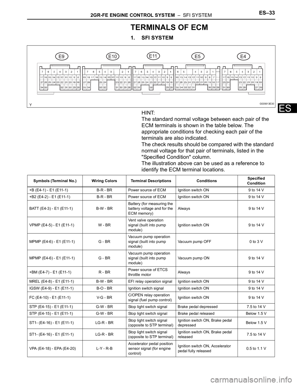
TERMINALS OF ECM
1. SFI SYSTEM
HINT:
The standard normal voltage between each pair of the
ECM terminals is shown in the table below. The
appropriate conditions for checking each pair of the
terminals are also indicated.
The check results should be compared with the standard
normal voltage for that pair of terminals, listed in the
"Specified Condition" column.
The illustration above can be used as a reference to
identify the ECM terminal locations.
G035613E30
Symbols (Terminal No.) Wiring Colors Terminal Descriptions ConditionsSpecified
Condition
+B (E4-1) - E1 (E11-1) B-R - BR Power source of ECM Ignition switch ON 9 to 14 V
+B2 (E4-2) - E1 (E11-1) B-R - BR Power source of ECM Ignition switch ON 9 to 14 V
BATT (E4-3) - E1 (E11-1) B-W - BRBattery (for measuring the
battery voltage and for the
ECM memory)Always 9 to 14 V
VPMP (E4-5) - E1 (E11-1) W - BRVent valve operation
signal (built into pump
module)Ignition switch ON 9 to 14 V
MPMP (E4-6) - E1 (E11-1) G - BRVacuum pump operation
signal (built into pump
module)Vacuum pump OFF 0 to 3 V
MPMP (E4-6) - E1 (E11-1) G - BRVacuum pump operation
signal (built into pump
module)Vacuum pump ON 9 to 14 V
+BM (E4-7) - E1 (E11-1) R - BRPower source of ETCS
throttle motorAlways 9 to 14 V
MREL (E4-8) - E1 (E11-1) B-W - BR EFI relay operation signal Ignition switch ON 9 to 14 V
IGSW (E4-9) - E1 (E11-1) B-O - BRIgnition switch signal Ignition switch ON 9 to 14 V
FC (E4-10) - E1 (E11-1) V-G - BRC/OPEN relay operation
signal (fuel pump control)Ignition switch ON 9 to 14 V
STP (E4-15) - E1 (E11-1) G-W - BR Stop light switch signal Brake pedal depressed 7.5 to 14 V
STP (E4-15) - E1 (E11-1) G-W - BR Stop light switch signal Brake pedal released Below 1.5 V
ST1- (E4-16) - E1 (E11-1) LG-R - BRStop light switch signal
(opposite to STP terminal)Ignition switch ON, Brake pedal
depressedBelow 1.5 V
ST1- (E4-16) - E1 (E11-1) LG-R - BRStop light switch signal
(opposite to STP terminal)Ignition switch ON, Brake pedal
released7.5 to 14 V
VPA (E4-18) - EPA (E4-20) L-Y - R-BAccelerator pedal position
sensor signal (for engine
control)Ignition switch ON, Accelerator
pedal fully released0.5 to 1.1 V
Page 815 of 3000

2GR-FE ENGINE CONTROL SYSTEM – SFI SYSTEMES–35
ES
STAR (NSW) (E10-8) - E1
(E11-1)B-Y - BRPark/Neutral position
switch signalIgnition switch ON, Shift lever
position P or N9 to 14 V
STAR (NSW) (E10-8) - E1
(E11-1)B-Y - BRPark/Neutral position
switch signalIgnition switch ON, Shift lever
position other than P or N9 to 14 V
STA (E11-11) - E1 (E11-1) B-L - BRStarter relay operation
signalCranking 9 to 14 V
OC2- (E11-14) - OC2+ (E11-
15)G-B - L-RCamshaft timing Oil
Control Valve (OCV)
operation signal (Intake
side)Ignition switch ONPulse generation
(see waveform 1)
OE2+ (E11-27) - OE2- (E11-
32)W - G-RCamshaft timing Oil
Control Valve (OCV)
operation signal (Intake
side)Ignition switch ONPulse generation
(see waveform 1)
OC1- (E11-16) - OC1+ (E11-
17)G-R - G-WCamshaft timing Oil
Control Valve (OCV)
operation signal (Intake
side)Ignition switch ONPulse generation
(see waveform 1)
OE1+ (E11-26) - OE1- (E11-
31)G - RCamshaft timing Oil
Control Valve (OCV)
operation signal (Intake
side)Ignition switch ONPulse generation
(see waveform 1)
VV2+ (E11-18) - VV2- (E11-
28)V - GVariable Valve Timing
(VVT) sensor signal
(Intake side)IdlingPulse generation
(see waveform 5)
VV1+ (E11-19) - VV1- (E11-
29)B-W - L-YVariable Valve Timing
(VVT) sensor signal
(Intake side)IdlingPulse generation
(see waveform 5)
NE- (E11-20) - NE+ (E11-21) B - WCrankshaft position sensor
signalIdlingPulse generation
(see waveform 5)
NE+ (E11-21) - NE- (E11-20) W - BCrankshaft position sensor
signalIdlingPulse generation
(see waveform 5)
EV2- (E11-22) - EV2+ (E11-
23)R - PVariable Valve Timing
(VVT) sensor signal
(Exhaust side)IdlingPulse generation
(see waveform 5)
EV2+ (E11-23) - EV2- (E11-
22)P - RVariable Valve Timing
(VVT) sensor signal
(Exhaust side)IdlingPulse generation
(see waveform 5)
EV1- (E11-24) - EV1+ (E11-
25)L-W - B-WVariable Valve Timing
(VVT) sensor signal
(Exhaust side)IdlingPulse generation
(see waveform 5)
EV1+ (E11-25) - EV1- (E11-
24)B-W - L-WVariable Valve Timing
(VVT) sensor signal
(Exhaust side)IdlingPulse generation
(see waveform 5)
VV2- (E11-28) - VV2+ (E11-
18)G - VVariable Valve Timing
(VVT) sensor signal
(Intake side)IdlingPulse generation
(see waveform 5)
VV1- (E11-29) - VV1+ (E11-
19)L-Y - B-WVariable Valve Timing
(VVT) sensor signal
(Intake side)IdlingPulse generation
(see waveform 5)
HT1B (E9-1) - E1 (E11-1)
HT2B (E10-5) - E1 (E11-1)L - BR
W-L - BRHeated oxygen sensor
heater operation signalIdling Below 3.0 V
HT1B (E9-1) - E1 (E11-1)
HT2B (E10-5) - E1 (E11-1)L - BR
W-L - BRHeated oxygen sensor
heater operation signalIgnition switch ON 9 to 14 V
ACM (E9-3) - E1 (E11-1) Y-G - BRVSV for active control
mount system operation
signalIgnition switch ON 9 to 14 V
M- (E9-4) - ME01 (E10-3) W - W-BThrottle drive motor
operation signal (negative
terminal)Idling with warm enginePulse generation
(see waveform 10) Symbols (Terminal No.) Wiring Colors Terminal Descriptions ConditionsSpecified
Condition
Page 827 of 3000

2GR-FE ENGINE CONTROL SYSTEM – SFI SYSTEMES–45
ES
DTC CHECK / CLEAR
NOTICE:
All the stored DTCs and freeze frame data are erased if:
1) the ECM is changed from normal mode to check mode
or vice versa; or 2) the ignition switch is turned from ON
to ACC or off while in check mode.
Before changing modes, always check and make a note
of any DTCs and freeze frame data.
HINT:
• DTCs which are stored in the ECM can be displayed on an
intelligent tester. An intelligent tester can display current
and pending DTCs.
• Some DTCs are not set if the ECM does not detect the
same malfunction again during the second consecutive
driving cycle. However, such malfunctions, detected on
only one occasion, are stored as pending DTCs.
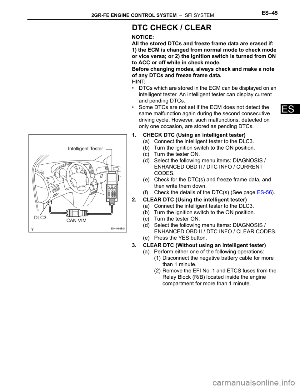
1. CHECK DTC (Using an intelligent tester)
(a) Connect the intelligent tester to the DLC3.
(b) Turn the ignition switch to the ON position.
(c) Turn the tester ON.
(d) Select the following menu items: DIAGNOSIS /
ENHANCED OBD II / DTC INFO / CURRENT
CODES.
(e) Check for the DTC(s) and freeze frame data, and
then write them down.
(f) Check the details of the DTC(s) (See page ES-56).
2. CLEAR DTC (Using the intelligent tester)
(a) Connect the intelligent tester to the DLC3.
(b) Turn the ignition switch to the ON position.
(c) Turn the tester ON.
(d) Select the following menu items: DIAGNOSIS /
ENHANCED OBD II / DTC INFO / CLEAR CODES.
(e) Press the YES button.
3. CLEAR DTC (Without using an intelligent tester)
(a) Perform either one of the following operations:
(1) Disconnect the negative battery cable for more
than 1 minute.
(2) Remove the EFI No. 1 and ETCS fuses from the
Relay Block (R/B) located inside the engine
compartment for more than 1 minute.
E144486E01
Page 846 of 3000
RF–4SLIDING ROOF – SLIDING ROOF SYSTEM
RF
PROBLEM SYMPTOMS TABLE
SLIDING ROOF SYSTEM
Symptom Suspected area See page
AUTO function does not operate Sliding roof motor assemblyRF-3
Sliding roof system does not operate1. ECU-IG fuse -
2. S/ Roof fuse -
3. IG1 relay -
4. Sliding roof housing assemblyRF-11
5. Sliding roof motor switch assemblyRF-13
6. Sliding roof motor assemblyRF-3
7. Wire harnessRF-3
Sliding roof system stops operation halfway1. Sliding roof motor assemblyRF-3
2. Wire harnessRF-3
3. Sliding roof housing assemblyRF-11