Page 2172 of 3000

AXLE – REAR AXLE HUB AND BEARING (for 2WD)AH–17
AH
REMOVAL
HINT:
Replace the RH side by the same procedures as the LH side.
1. REMOVE REAR WHEEL
2. REMOVE REAR DISC BRAKE CALIPER ASSEMBLY
LH
(a) Removing the 2 bolts, separate the rear disc brake
caliper assembly LH for disc rear brake type.
NOTICE:
Using a string and so on, hang down the disc
brake caliper.
3. REMOVE REAR DISC
(a) Remove rear disc for disc rear brake type.
4. REMOVE REAR BRAKE DRUM SUB-ASSEMBLY
(a) Remove rear brake drum sub-assembly for drum
rear brake type.
5. SEPARATE SKID CONTROL SENSOR WIRE
(a) Disconnect the connector
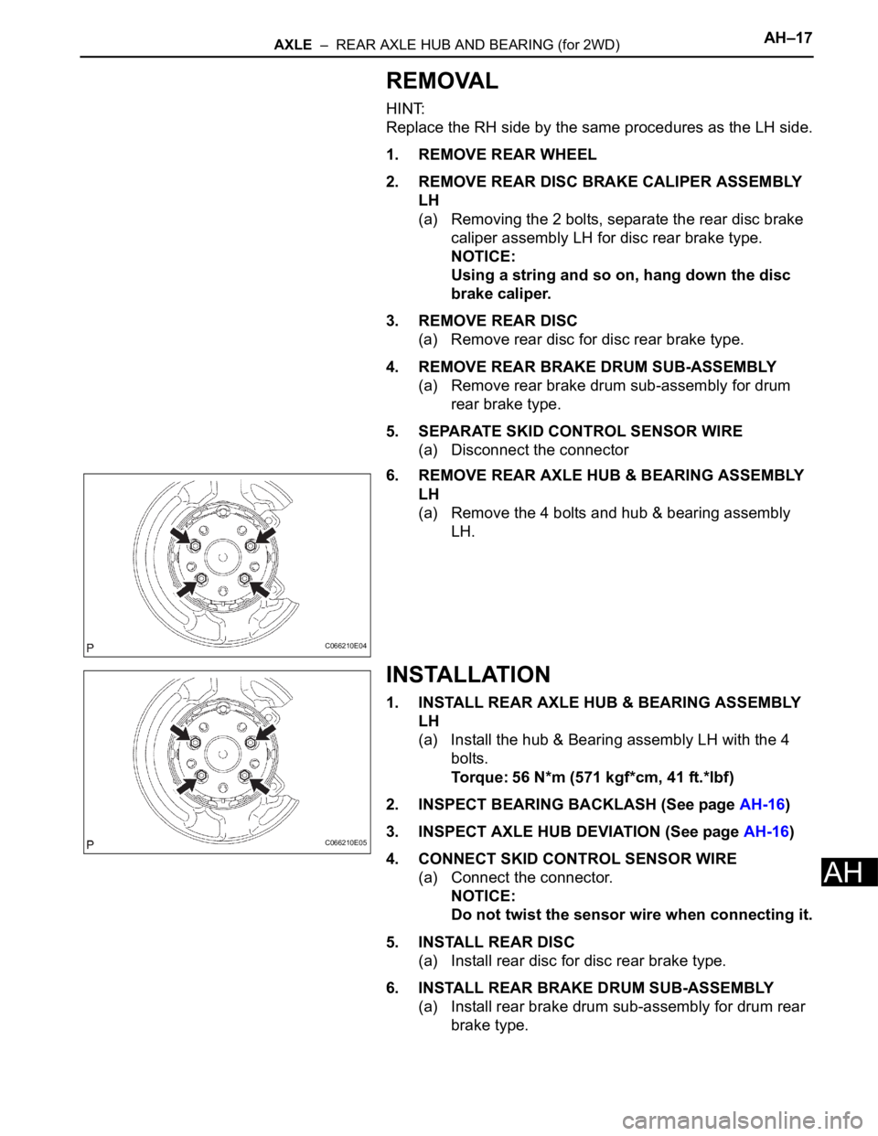
6. REMOVE REAR AXLE HUB & BEARING ASSEMBLY
LH
(a) Remove the 4 bolts and hub & bearing assembly
LH.
INSTALLATION
1. INSTALL REAR AXLE HUB & BEARING ASSEMBLY
LH
(a) Install the hub & Bearing assembly LH with the 4
bolts.
Torque: 56 N*m (571 kgf*cm, 41 ft.*lbf)
2. INSPECT BEARING BACKLASH (See page AH-16)
3. INSPECT AXLE HUB DEVIATION (See page AH-16)
4. CONNECT SKID CONTROL SENSOR WIRE
(a) Connect the connector.
NOTICE:
Do not twist the sensor wire when connecting it.
5. INSTALL REAR DISC
(a) Install rear disc for disc rear brake type.
6. INSTALL REAR BRAKE DRUM SUB-ASSEMBLY
(a) Install rear brake drum sub-assembly for drum rear
brake type.
C066210E04
C066210E05
Page 2173 of 3000
AH–18AXLE – REAR AXLE HUB AND BEARING (for 2WD)
AH
7. INSTALL REAR DISC BRAKE CALIPER ASSEMBLY
LH
(a) Install the rear disc brake caliper assembly LH with
the 2 bolts for disc rear brake type.
Torque: 88 N*m (900 kgf*cm, 65 ft.*lbf)
8. INSTALL REAR WHEEL
Torque: 103 N*m (1,050 kgf*cm, 76 ft.*lbf)
9. CHECK ABS SPEED SENSOR SIGNAL
(a) ABS WITH EBD SYSTEM (See page BC-3).
(b) ABS WITH EBD & BA & TRAC & VSC SYSTEM
(See page BC-72).
Page 2174 of 3000
AH–18AXLE – REAR AXLE HUB AND BEARING (for 4WD)
AH
SUSPENSION & AXLE
AXLE
REAR AXLE HUB AND BEARING (for 4WD)
COMPONENTS
C119309E04
Page 2175 of 3000
AXLE – REAR AXLE HUB AND BEARING (for 4WD)AH–19
AH
ON-VEHICLE INSPECTION
1. INSPECT REAR AXLE HUB BEARING BACKLASH
(a) Using a dial gauge, check for backlash near the
center of the axle hub.
Maximum:
0.05 mm (0.0020 in.)
If backlash exceeds the maximum, replace the axle
hub assembly.
NOTICE:
Ensure that the dial gauge is set at right angles
to the measurement surface.
2. INSPECT REAR AXLE HUB BEARING DEVIATION
(a) Using a dial gauge, check for deviation in the
surface of the axle hub outside the hub bolt.
Maximum:
0.07 mm (0.0027 in.)
If backlash exceeds the maximum, replace the axle
hub assembly.
NOTICE:
Ensure that the dial gauge is set at right angles
to the measurement surface.
C083015E04
C083016E04
Page 2176 of 3000

AH–20AXLE – REAR AXLE HUB AND BEARING (for 4WD)
AH
REMOVAL
HINT:
Replace the RH side by the same procedures as the LH side.
1. REMOVE REAR WHEEL
2. REMOVE REAR AXLE SHAFT LH NUT (See page DS-
22)
3. SEPARATE REAR DISC BRAKE CALIPER
ASSEMBLY LH
(a) Removing the 2 bolts, separate the rear disc brake
caliper assembly LH.
4. REMOVE REAR DISC
5. SEPARATE SPEED SENSOR REAR LH
(a) Removing the bolt, separate the speed sensor rear
LH.
NOTICE:
• Be careful not to damage the speed sensor.
• Prevent foreign matter from attaching to the
speed sensor.
6. REMOVE REAR DRIVE SHAFT ASSEMBLY LH (See
page DS-22)
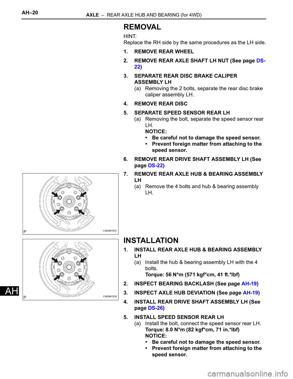
7. REMOVE REAR AXLE HUB & BEARING ASSEMBLY
LH
(a) Remove the 4 bolts and hub & bearing assembly
LH.
INSTALLATION
1. INSTALL REAR AXLE HUB & BEARING ASSEMBLY
LH
(a) Install the hub & bearing assembly LH with the 4
bolts.
Torque: 56 N*m (571 kgf*cm, 41 ft.*lbf)
2. INSPECT BEARING BACKLASH (See page AH-19)
3. INSPECT AXLE HUB DEVIATION (See page AH-19)
4. INSTALL REAR DRIVE SHAFT ASSEMBLY LH (See
page DS-26)
5. INSTALL SPEED SENSOR REAR LH
(a) Install the bolt, connect the speed sensor rear LH.
Torque: 8.0 N*m (82 kgf*cm, 71 in.*lbf)
NOTICE:
• Be careful not to damage the speed sensor.
• Prevent foreign matter from attaching to the
speed sensor.
C065991E01
C065991E02
Page 2177 of 3000
AXLE – REAR AXLE HUB AND BEARING (for 4WD)AH–21
AH
• Do not twist the sensor wire when installing
the sensor.
6. INSTALL REAR DISC
7. INSTALL REAR DISC BRAKE CALIPER ASSEMBLY
LH
(a) Install the rear disc brake caliper assembly LH with
the 2 bolts.
Torque: 88 N*m (900 kgf*cm, 65 ft.*lbf)
8. INSTALL REAR AXLE SHAFT LH NUT (See page DS-
26)
9. INSTALL REAR WHEEL
Torque: 103 N*m (1,050 kgf*cm, 76 ft.*lbf)
10. CHECK ABS SPEED SENSOR SIGNAL
(a) ABS WITH EBD & BA & TRAC & VSC SYSTEM
(See page BC-72).
Page 2236 of 3000

SP–58SUSPENSION – REAR AXLE BEAM
SP
13. SEPARATE PARKING BRAKE CABLE ASSEMBLY
NO.2
HINT:
Separate the RH side by the same procedures as the LH
side.
14. SEPARATE REAR BRAKE TUBE NO.2
HINT:
(See page SP-38)
SST 09023-00101
15. SEPARATE REAR BRAKE TUBE NO.1
SST 09023-00101
HINT:
Separate the RH side by the same procedures as the LH
side.
16. REMOVE FUEL TANK FILLER HOSE COVER
HINT:
(See page SP-38)
17. REMOVE REAR FLOOR NO.2 CROSSMEMBER
BRACE LH
HINT:
(See page SP-38)
18. REMOVE REAR FLOOR NO.2 CROSSMEMBER
BRACE RH
HINT:
Remove the RH side by the same procedures as the LH
side.
19. LOOSEN REAR AXLE BEAM ASSEMBLY
HINT:
(See page SP-38)
20. SEPARATE REAR DISC BRAKE CALIPER
ASSEMBLY LH (for DISC REAR BRAKE)
(a) Remove the 2 bolts and separate the rear disc
brake caliper assembly LH.
21. SEPARATE REAR DISC BRAKE CALIPER
ASSEMBLY RH (for DISC REAR BRAKE)
HINT:
Separate the RH side by the same procedures as the LH
side.
22. REMOVE REAR DISC (for DISC REAR BRAKE)
23. REMOVE REAR BRAKE DRUM SUB-ASSEMBLY (for
DRUM REAR BRAKE)
24. REMOVE REAR AXLE HUB & BEARING ASSEMBLY
LH (for 2WD)
HINT:
(See page AH-15)
Page 2237 of 3000

SUSPENSION – REAR AXLE BEAMSP–59
SP
25. REMOVE REAR AXLE HUB & BEARING ASSEMBLY
RH (for 2WD)
HINT:
Remove the RH side by the same procedures as the LH
side.
26. REMOVE REAR AXLE HUB & BEARING ASSEMBLY
LH (for 4WD)
HINT:
(See page AH-18)
27. REMOVE REAR AXLE HUB & BEARING ASSEMBLY
RH (for 4WD)
HINT:
Remove the RH side by the same procedures as the LH
side.
28. REMOVE PARKING BRAKE PLATE SUB-ASSEMBLY
LH (for DISC REAR BRAKE)
(a) 2WD DRIVE TYPE: Remove the rear axle bearing
retainer inner LH and parking brake plate sub-
assembly LH.
(b) 4WD DRIVE TYPE: Remove the rear axle bearing
retainer outer and parking brake plate sub-assembly
LH.
29. REMOVE PARKING BRAKE PLATE SUB-ASSEMBLY
RH (for DISC REAR BRAKE)
HINT:
Remove the RH side by the same procedures as the LH
side.
30. REMOVE BRAKE BACKING PLATE SUB-ASSEMBLY
LH (DRUM REAR BRAKE)
(a) Remove the 2 rear axle bearing retainer inner LH
and parking brake plate sub-assembly LH.
31. REMOVE BRAKE BACKING PLATE SUB-ASSEMBLY
RH (for DRUM REAR BRAKE)
HINT:
Remove the RH side by the same procedures as the LH
side.
32. SEPARATE SHOCK ABSORBER ASSEMBLY REAR
LH
HINT:
(See page SP-38)
33. SEPARATE SHOCK ABSORBER ASSEMBLY REAR
RH
HINT:
Separate the RH side by the same procedures as the LH
side.
34. REMOVE COIL SPRING REAR LH
HINT:
(See page SP-38)