Page 1868 of 3000
U151F AUTOMATIC TRANSAXLE – AUTOMATIC TRANSAXLE UNITAX–193
AX
48. REMOVE GOVERNOR APPLY GASKET NO.1
(a) Using a screwdriver, remove the 3 apply gaskets.
49. REMOVE BRAKE APPLY TUBE
(a) Remove the bolt, clamp and brake apply tube.
(b) Remove the clutch apply tube.
(c) Remove the brake apply tube from the clamp.
NOTICE:
Do not bend the tubes.
50. REMOVE DIRECT CLUTCH ASSEMBLY
(a) Remove the thrust bearing and the direct clutch
assembly from the transaxle case.
51. REMOVE OVERDRIVE DIRECT CLUTCH HUB SUB-
ASSEMBLY
(a) Remove the thrust bearing race, thrust bearing and
overdrive direct clutch hub from the planetary gear
assembly.
52. INSPECT OVERDRIVE DIRECT CLUTCH DRUM SUB-
ASSEMBLY
HINT:
(See page AX-202)
53. REMOVE REAR PLANETARY SUN GEAR ASSEMBLY
(a) Remove the rear planetary sun gear assembly from
the transaxle case.
D026390
D026391E03
D026403E02
D026392E03
D026714E02
Page 1896 of 3000
U151F AUTOMATIC TRANSAXLE – AUTOMATIC TRANSAXLE UNITAX–213
AX
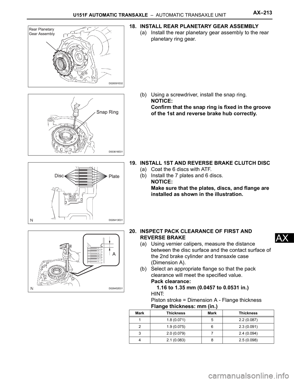
18. INSTALL REAR PLANETARY GEAR ASSEMBLY
(a) Install the rear planetary gear assembly to the rear
planetary ring gear.
(b) Using a screwdriver, install the snap ring.
NOTICE:
Confirm that the snap ring is fixed in the groove
of the 1st and reverse brake hub correctly.
19. INSTALL 1ST AND REVERSE BRAKE CLUTCH DISC
(a) Coat the 6 discs with ATF.
(b) Install the 7 plates and 6 discs.
NOTICE:
Make sure that the plates, discs, and flange are
installed as shown in the illustration.
20. INSPECT PACK CLEARANCE OF FIRST AND
REVERSE BRAKE
(a) Using vernier calipers, measure the distance
between the disc surface and the contact surface of
the 2nd brake cylinder and transaxle case
(Dimension A).
(b) Select an appropriate flange so that the pack
clearance will meet the specified value.
Pack clearance:
1.16 to 1.35 mm (0.0457 to 0.0531 in.)
HINT:
Piston stroke = Dimension A - Flange thickness
Flange thickness: mm (in.)
D026591E02
D003616E01
D026413E01
D026452E01
Mark Thickness Mark Thickness
1 1.8 (0.071) 5 2.2 (0.087)
2 1.9 (0.075) 6 2.3 (0.091)
3 2.0 (0.079) 7 2.4 (0.094)
4 2.1 (0.083) 8 2.5 (0.098)
Page 1900 of 3000
U151F AUTOMATIC TRANSAXLE – AUTOMATIC TRANSAXLE UNITAX–217
AX
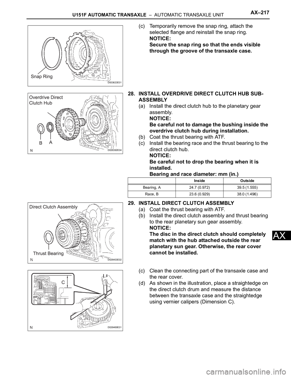
(c) Temporarily remove the snap ring, attach the
selected flange and reinstall the snap ring.
NOTICE:
Secure the snap ring so that the ends visible
through the groove of the transaxle case.
28. INSTALL OVERDRIVE DIRECT CLUTCH HUB SUB-
ASSEMBLY
(a) Install the direct clutch hub to the planetary gear
assembly.
NOTICE:
Be careful not to damage the bushing inside the
overdrive clutch hub during installation.
(b) Coat the thrust bearing with ATF.
(c) Install the bearing race and the thrust bearing to the
direct clutch hub.
NOTICE:
Be careful not to drop the bearing when it is
installed.
Bearing and race diameter: mm (in.)
29. INSTALL DIRECT CLUTCH ASSEMBLY
(a) Coat the thrust bearing with ATF.
(b) Install the direct clutch assembly and thrust bearing
to the rear planetary sun gear assembly.
NOTICE:
The disc in the direct clutch should completely
match with the hub attached outside the rear
planetary sun gear. Otherwise, the rear cover
cannot be installed.
(c) Clean the connecting part of the transaxle case and
the rear cover.
(d) As shown in the illustration, place a straightedge on
the direct clutch drum and measure the distance
between the transaxle case and the straightedge
using vernier calipers (Dimension C).
D003623E01
D026392E04
Inside Outside
Bearing, A 24.7 (0.972) 39.5 (1.555)
Race, B 23.6 (0.929) 38.0 (1.496)
D026403E02
D026469E01
Page 1934 of 3000
U151F AUTOMATIC TRANSAXLE – AUTOMATIC TRANSAXLE UNITAX–193
AX
48. REMOVE GOVERNOR APPLY GASKET NO.1
(a) Using a screwdriver, remove the 3 apply gaskets.
49. REMOVE BRAKE APPLY TUBE
(a) Remove the bolt, clamp and brake apply tube.
(b) Remove the clutch apply tube.
(c) Remove the brake apply tube from the clamp.
NOTICE:
Do not bend the tubes.
50. REMOVE DIRECT CLUTCH ASSEMBLY
(a) Remove the thrust bearing and the direct clutch
assembly from the transaxle case.
51. REMOVE OVERDRIVE DIRECT CLUTCH HUB SUB-
ASSEMBLY
(a) Remove the thrust bearing race, thrust bearing and
overdrive direct clutch hub from the planetary gear
assembly.
52. INSPECT OVERDRIVE DIRECT CLUTCH DRUM SUB-
ASSEMBLY
HINT:
(See page AX-202)
53. REMOVE REAR PLANETARY SUN GEAR ASSEMBLY
(a) Remove the rear planetary sun gear assembly from
the transaxle case.
D026390
D026391E03
D026403E02
D026392E03
D026714E02
Page 2075 of 3000
DS–22DRIVE SHAFT – REAR DRIVE SHAFT (for 4WD)
DS
REMOVAL
1. REMOVE REAR WHEEL
2. REMOVE TAIL EXHAUST PIPE ASSEMBLY (See page
EX-8)
3. SEPARATE REAR SPEED SENSOR
(a) Remove the bolt and the speed sensor from the
axle carrier.
NOTICE:
• Be careful not to damage the speed sensor.
• Prevent foreign matter from adhering to the
speed sensor.
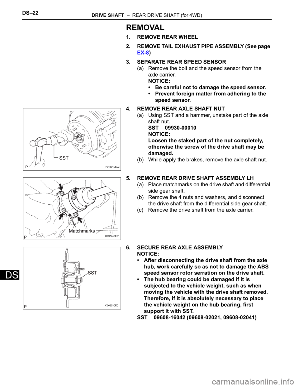
4. REMOVE REAR AXLE SHAFT NUT
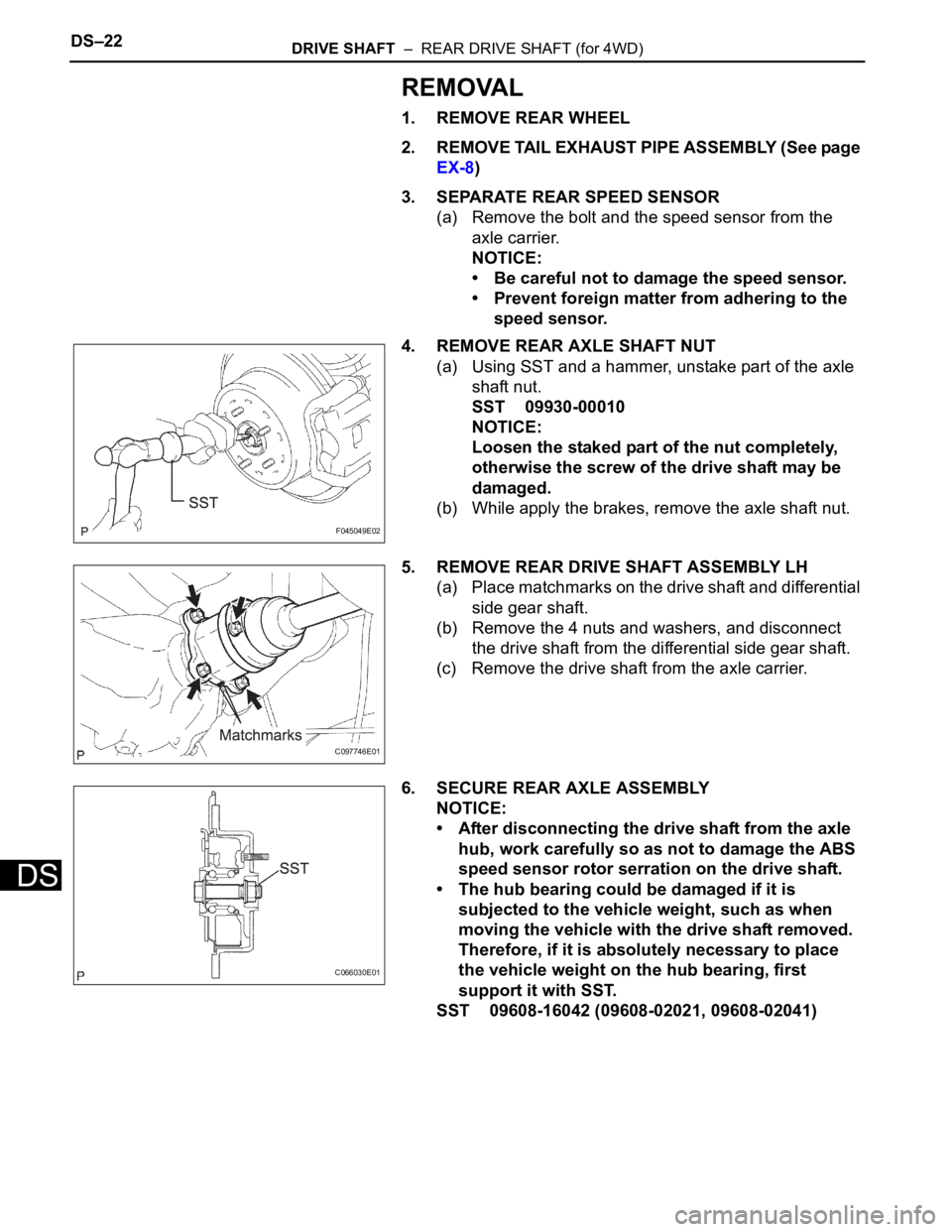
(a) Using SST and a hammer, unstake part of the axle
shaft nut.
SST 09930-00010
NOTICE:
Loosen the staked part of the nut completely,
otherwise the screw of the drive shaft may be
damaged.
(b) While apply the brakes, remove the axle shaft nut.
5. REMOVE REAR DRIVE SHAFT ASSEMBLY LH
(a) Place matchmarks on the drive shaft and differential
side gear shaft.
(b) Remove the 4 nuts and washers, and disconnect
the drive shaft from the differential side gear shaft.
(c) Remove the drive shaft from the axle carrier.
6. SECURE REAR AXLE ASSEMBLY
NOTICE:
• After disconnecting the drive shaft from the axle
hub, work carefully so as not to damage the ABS
speed sensor rotor serration on the drive shaft.
• The hub bearing could be damaged if it is
subjected to the vehicle weight, such as when
moving the vehicle with the drive shaft removed.
Therefore, if it is absolutely necessary to place
the vehicle weight on the hub bearing, first
support it with SST.
SST 09608-16042 (09608-02021, 09608-02041)
F045049E02
C097746E01
C066030E01
Page 2096 of 3000
DRIVE SHAFT – REAR DRIVE SHAFT (for 4WD)DS–27
DS
INSTALLATION
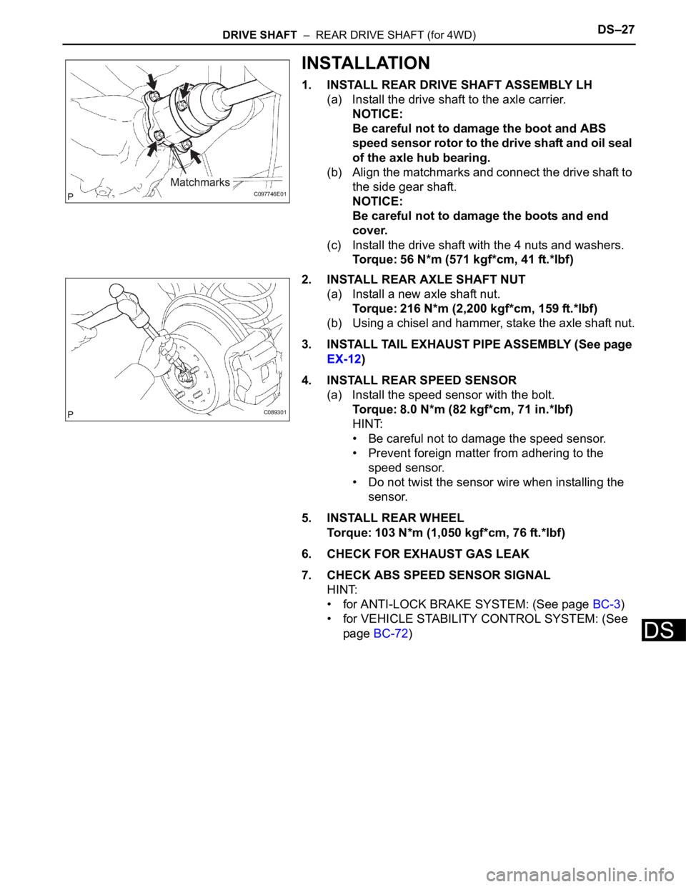
1. INSTALL REAR DRIVE SHAFT ASSEMBLY LH
(a) Install the drive shaft to the axle carrier.
NOTICE:
Be careful not to damage the boot and ABS
speed sensor rotor to the drive shaft and oil seal
of the axle hub bearing.
(b) Align the matchmarks and connect the drive shaft to
the side gear shaft.
NOTICE:
Be careful not to damage the boots and end
cover.
(c) Install the drive shaft with the 4 nuts and washers.
Torque: 56 N*m (571 kgf*cm, 41 ft.*lbf)
2. INSTALL REAR AXLE SHAFT NUT
(a) Install a new axle shaft nut.
Torque: 216 N*m (2,200 kgf*cm, 159 ft.*lbf)
(b) Using a chisel and hammer, stake the axle shaft nut.
3. INSTALL TAIL EXHAUST PIPE ASSEMBLY (See page
EX-12)
4. INSTALL REAR SPEED SENSOR
(a) Install the speed sensor with the bolt.
Torque: 8.0 N*m (82 kgf*cm, 71 in.*lbf)
HINT:
• Be careful not to damage the speed sensor.
• Prevent foreign matter from adhering to the
speed sensor.
• Do not twist the sensor wire when installing the
sensor.
5. INSTALL REAR WHEEL
Torque: 103 N*m (1,050 kgf*cm, 76 ft.*lbf)
6. CHECK FOR EXHAUST GAS LEAK
7. CHECK ABS SPEED SENSOR SIGNAL
HINT:
• for ANTI-LOCK BRAKE SYSTEM: (See page BC-3)
• for VEHICLE STABILITY CONTROL SYSTEM: (See
page BC-72)
C097746E01
C089301
Page 2097 of 3000
DS–22DRIVE SHAFT – REAR DRIVE SHAFT (for 4WD)
DS
REMOVAL
1. REMOVE REAR WHEEL
2. REMOVE TAIL EXHAUST PIPE ASSEMBLY (See page
EX-8)
3. SEPARATE REAR SPEED SENSOR
(a) Remove the bolt and the speed sensor from the
axle carrier.
NOTICE:
• Be careful not to damage the speed sensor.
• Prevent foreign matter from adhering to the
speed sensor.
4. REMOVE REAR AXLE SHAFT NUT
(a) Using SST and a hammer, unstake part of the axle
shaft nut.
SST 09930-00010
NOTICE:
Loosen the staked part of the nut completely,
otherwise the screw of the drive shaft may be
damaged.
(b) While apply the brakes, remove the axle shaft nut.
5. REMOVE REAR DRIVE SHAFT ASSEMBLY LH
(a) Place matchmarks on the drive shaft and differential
side gear shaft.
(b) Remove the 4 nuts and washers, and disconnect
the drive shaft from the differential side gear shaft.
(c) Remove the drive shaft from the axle carrier.
6. SECURE REAR AXLE ASSEMBLY
NOTICE:
• After disconnecting the drive shaft from the axle
hub, work carefully so as not to damage the ABS
speed sensor rotor serration on the drive shaft.
• The hub bearing could be damaged if it is
subjected to the vehicle weight, such as when
moving the vehicle with the drive shaft removed.
Therefore, if it is absolutely necessary to place
the vehicle weight on the hub bearing, first
support it with SST.
SST 09608-16042 (09608-02021, 09608-02041)
F045049E02
C097746E01
C066030E01
Page 2100 of 3000
DRIVE SHAFT – REAR DRIVE SHAFT (for 4WD)DS–27
DS
INSTALLATION
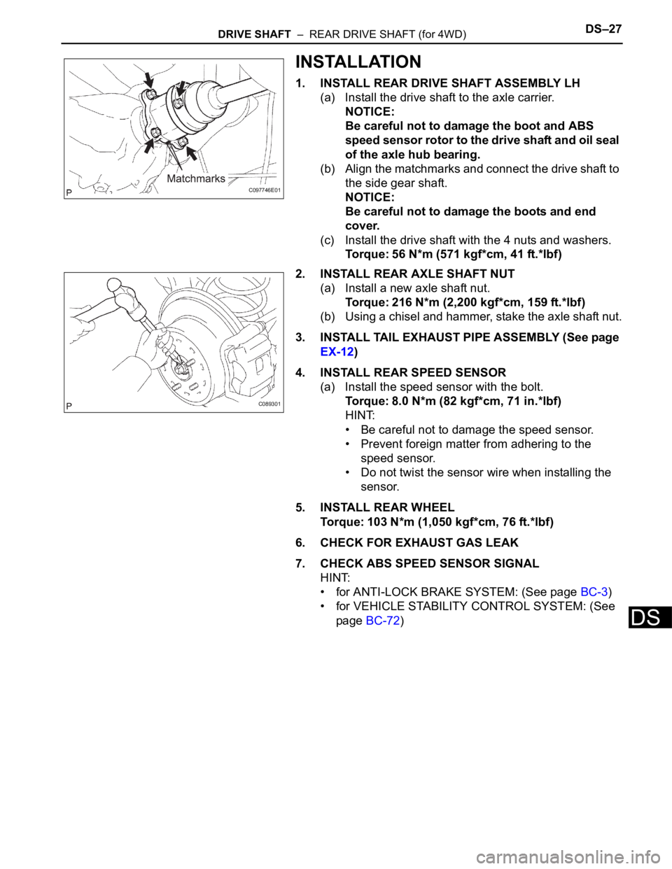
1. INSTALL REAR DRIVE SHAFT ASSEMBLY LH
(a) Install the drive shaft to the axle carrier.
NOTICE:
Be careful not to damage the boot and ABS
speed sensor rotor to the drive shaft and oil seal
of the axle hub bearing.
(b) Align the matchmarks and connect the drive shaft to
the side gear shaft.
NOTICE:
Be careful not to damage the boots and end
cover.
(c) Install the drive shaft with the 4 nuts and washers.
Torque: 56 N*m (571 kgf*cm, 41 ft.*lbf)
2. INSTALL REAR AXLE SHAFT NUT
(a) Install a new axle shaft nut.
Torque: 216 N*m (2,200 kgf*cm, 159 ft.*lbf)
(b) Using a chisel and hammer, stake the axle shaft nut.
3. INSTALL TAIL EXHAUST PIPE ASSEMBLY (See page
EX-12)
4. INSTALL REAR SPEED SENSOR
(a) Install the speed sensor with the bolt.
Torque: 8.0 N*m (82 kgf*cm, 71 in.*lbf)
HINT:
• Be careful not to damage the speed sensor.
• Prevent foreign matter from adhering to the
speed sensor.
• Do not twist the sensor wire when installing the
sensor.
5. INSTALL REAR WHEEL
Torque: 103 N*m (1,050 kgf*cm, 76 ft.*lbf)
6. CHECK FOR EXHAUST GAS LEAK
7. CHECK ABS SPEED SENSOR SIGNAL
HINT:
• for ANTI-LOCK BRAKE SYSTEM: (See page BC-3)
• for VEHICLE STABILITY CONTROL SYSTEM: (See
page BC-72)
C097746E01
C089301