2007 TOYOTA SIENNA fuel cap
[x] Cancel search: fuel capPage 479 of 3000

2GR-FE ENGINE CONTROL SYSTEM – SFI SYSTEMES–173
ES
TYPICAL ENABLING CONDITIONS
All:
Heated Oxygen Sensor Output Voltage (Output Voltage, High Voltage and Low Voltage):
Heated Oxygen Sensor Impedance (Low):
Heated Oxygen Sensor Impedance (High):
Heated Oxygen Sensor Output Voltage (Extremely High):
TYPICAL MALFUNCTION THRESHOLDS
Heated Oxygen Sensor Output Voltage (Output voltage):
Heated Oxygen Sensor Output Voltage (Low output voltage):
The monitor will run whenever these DTCs are not
presentP0031, P0032, P0051, P0052 (A/F Sensor Heater Sensor 1), P0100, P0101, P0102,
P0103 (MAF Sensor), P0110, P0112, P0113 (IAT Sensor), P0115, P0116, P0117,
P0118 (ECT Sensor), P0120, P0121, P0122, P0123, P0220, P0222, P0223, P2135
(TP Sensor), P0125 (Insufficient ECT for Closed Loop), P0171, P0172 (Fuel
System), P0300, P0301, P0302, P0303, P0304, P0305, P0306 (Misfire), P0335
(CKP Sensor), P0340 (CMP Sensor), P0500 (VSS), P2196, P2198 (A/F Sensor
(Rationality)), P2A00, P2A03 (A/F Sensor (Slow Response))
Active air-fuel ratio control Performing
Active air-fuel ratio control is performed when the
following conditions are met:-
Battery voltage 11 V or more
Engine coolant temperature 75
C (167F) or more
Idle OFF
Engine RPM Less than 3200 rpm
A/F sensor status Activated
Fuel system status Closed loop
Fuel-cut OFF
Engine load 10 to 70%
Shift position 4th or more
Battery voltage 11 V or more
Estimated HO2S temperature Less than 700
C (1292F)
ECM monitor Completed
DTC P0606 Not set
Battery voltage 11 V or more
Estimated HO2S temperature 450
C (842F) or more
DTC P0606 Not set
Battery voltage 11 V or more
Time after engine start 2 seconds or more
Either of the following conditions is met: 1 or 2
1. All of the following conditions (a), (b) and (c) are met -
(a) Commanded air-fuel ratio 14.3 or less
(b) Rear HO2 sensor voltage 0.21 to 0.59 V
(c) OSC (Oxygen Storage Capacity of Catalyst) 2.0 g (0.0044 lb) or more
2. All of the following conditions (d), (f) and (g) are met. -
(d) Commanded air-fuel ratio 14.9 or more
(f) Rear HO2 sensor voltage 0.21 to 0.59 V
(g) OSC 2.0 g (0.0044 lb) or more
All of the following conditions (a), (b) and (c) are met. -
(a) Commanded air-fuel ratio 14.3 or less
Page 480 of 3000

ES–1742GR-FE ENGINE CONTROL SYSTEM – SFI SYSTEM
ES
Heated Oxygen Sensor Output Voltage (High output voltage):
Heated Oxygen Sensor Impedance (Low):
Heated Oxygen Sensor Impedance (High):
Heated Oxygen Sensor Impedance (Extremely High):
COMPONENT OPERATING RANGE
MONITOR RESULT
Refer to CHECKING MONITOR STATUS (See page ES-19).
(b) Rear HO2 sensor voltage Less than 0.21 V
(c) OSC (Oxygen Storage Capacity of Catalyst) 2.0 g (0.0044 lb) or more
All of the following conditions (a), (b) and (c) are met. -
(a) Commanded air-fuel ratio 14.9 or more
(b) Rear HO2 sensor voltage More than 0.59 V
(c) OSC (Oxygen Storage Capacity of Catalyst) 2.0 g (0.0044 lb) or more
Duration that following condition is met 30 seconds or more
Rear heated oxygen sensor impedance Less than 5
Duration that following condition is met 90 seconds or more
Rear heated oxygen sensor impedance 15 k
or more
Duration that following condition is met 10 seconds or more
Rear heated oxygen sensor voltage 1.2 V or more
Duration that following condition is met 30 seconds or more
Heated oxygen sensor voltage Varies between 0.1 and 0.9 V
Page 574 of 3000
2GR-FE ENGINE CONTROL SYSTEM – SFI SYSTEMES–281
ES
INSPECTION PROCEDURE
NOTICE:
• When a vehicle is brought into the workshop, leave it as it is. Do not change the vehicle
condition. For example, do not tighten the fuel cap.
• Do not disassemble the canister pump module.
• The intelligent tester is required to conduct the following diagnostic troubleshooting
procedure.
(a) Connect the intelligent tester to the DLC3.
(b) Turn the ignition switch to the ON position (do not start
the engine).
(c) Turn the tester on.
(d) Select the following menu items: DIAGNOSIS /
ENHANCED OBD II / DTC INFO / CURRENT CODES.
(e) Read DTCs.
(f) Select the following menu items: DIAGNOSIS /
ENHANCED OBD II / DATA LIST / EVAP / EVAP VAPOR
PRESS.
(g) Read the EVAP (Evaporative Emission) pressure
displayed on the tester.
Result
B
C
A
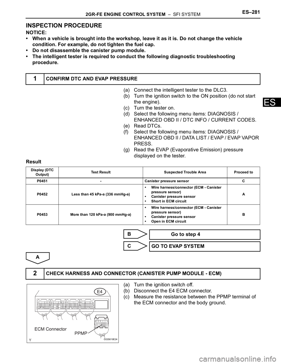
(a) Turn the ignition switch off.
(b) Disconnect the E4 ECM connector.
(c) Measure the resistance between the PPMP terminal of
the ECM connector and the body ground.
1CONFIRM DTC AND EVAP PRESSURE
Display (DTC
Output)Test Result Suspected Trouble Area Proceed to
P0451 - Canister pressure sensor C
P0452 Less than 45 kPa-a (336 mmHg-a)• Wire harness/connector (ECM - Canister
pressure sensor)
• Canister pressure sensor
• Short in ECM circuitA
P0453 More than 120 kPa-a (900 mmHg-a)• Wire harness/connector (ECM - Canister
pressure sensor)
• Canister pressure sensor
• Open in ECM circuitB
Go to step 4
GO TO EVAP SYSTEM
2CHECK HARNESS AND CONNECTOR (CANISTER PUMP MODULE - ECM)
G035619E24
Page 579 of 3000

ES–2862GR-FE ENGINE CONTROL SYSTEM – SFI SYSTEM
ES
DTC SUMMARY
DESCRIPTION
The circuit description can be found in the EVAP (Evaporative Emission) System (See page ES-409).
INSPECTION PROCEDURE
Refer to the EVAP System (See page ES-412).
MONITOR DESCRIPTION
5 hours*1 after the ignition switch is turned off, the electric vacuum pump creates negative pressure
(vacuum) in the EVAP (Evaporative Emission) system. The ECM monitors for leaks and actuator
malfunctions based on the EVAP pressure.
HINT:
*1: If the engine coolant temperature is not below 35
C (95F) 5 hours after the ignition switch is turned
off, the monitor check starts 2 hours later. If it is still not below 35
C (95F) 7 hours after the ignition switch
is turned off, the monitor check starts 2.5 hours later.
DTC P0455Evaporative Emission Control System Leak
Detected (Gross Leak)
DTC P0456Evaporative Emission Control System Leak
Detected (Very Small Leak)
DTCs Monitoring ItemMalfunction Detection
ConditionTrouble Area Detection TimingDetection
Logic
P0455 EVAP gross leakVacuum pump creates negative
pressure (vacuum) in EVAP
system and EVAP system
pressure is measured. 0.02 inch
leak pressure standard is
measured at start and end of leak
check.
If stabilized pressure is higher
than [second 0.02 inch leak
pressure standard x 0.2], ECM
determines that EVAP system
has a large leak.• Fuel tank cap (loose)
• Leakage from EVAP
line (Canister - Fuel
tank)
• Leakage from EVAP
line (Purge VSV -
Canister)
• Leakage from pump
module
• Leakage from fuel
tank
• Leakage from canisterWhile ignition
switch OFF2 trip
P0456 EVAP small leakVacuum pump creates negative
pressure (vacuum) in EVAP
system and EVAP system
pressure is measured. 0.02 inch
leak pressure standard measured
at start and end of leak check.
If stabilized pressure is higher
than second 0.02 inch leak
pressure standard, ECM
determines that EVAP system
has a small leak.While ignition
switch OFF2 trip
Sequence Operation Description Duration
- ECM activationActivated by soak timer, 5 hours (7 or 9.5 hours) after ignition switch is
turned off.-
AAtmospheric pressure
measurementVent valve is turned OFF (vent) and EVAP system pressure is
measured by ECM in order to register atmospheric pressure.
If pressure in EVAP system is not between 70 kPa and 110 kPa (525
mmHg and 825 mmHg), ECM cancels EVAP system monitor.10 seconds
Page 700 of 3000

ES–4142GR-FE ENGINE CONTROL SYSTEM – SFI SYSTEM
ES
(2) Turn the ignition switch off and wait for 6 hours (8 or 10.5 hours).
HINT:
Do not start the engine until checking MONITOR STATUS. If the engine is started, the steps
described above must be repeated.
(c) Monitor Status
(1) Connect the intelligent tester to the DLC3.
(2) Turn the ignition switch to the ON position and turn the tester on.
(3) Select the following menu items: DIAGNOSIS / ENHANCED OBD II / MONITOR STATUS.
(4) Check the "Monitor Status" displayed on the tester.
HINT:
If INCMP is displayed, the monitor is not completed. Make sure that the preconditions have
been met, and perform "Monitor Conditions" again.
2. PURGE FLOW MONITOR CONFIRMATION (P0441)
HINT:
Perform this monitor confirmation after the Key-Off Monitor Confirmation shows COMPL (complete).
(a) Preconditions
The monitor will not run unless:
• The vehicle has been driven for 10 minutes or more (in a city area or on a freeway)
• The ECT is between 4.4
C and 35C (40F and 95F)
• The IAT is between 4.4
C and 35C (40F and 95F)
(b) Monitor Conditions
(1) Release the pressure from the fuel tank by removing and reinstalling the fuel tank cap.
(2) Warm the engine up until the ECT reaches more than 75
C (167F).
(3) Increase the engine speed to 3000 rpm once.
(4) Allow the engine to idle and turn the A/C ON for 1 minute.
(c) Monitor Status
(1) Turn the ignition switch off.
(2) Connect the intelligent tester to the DLC3.
(3) Turn the ignition switch to the ON position and turn the tester on.
(4) Select the following menu items: DIAGNOSIS / ENHANCED OBD II / MONITOR STATUS.
(5) Check the "Monitor Status" displayed on the tester.
HINT:
If INCMP is displayed, the monitor is not completed. Make sure that the preconditions have
been met, and perform "Monitor Conditions" again.
MONITOR RESULT
Refer to Checking Monitor Status for detailed information (See page ES-19).
The test value and test limit information are described as shown in the following table. This information is
included in MONITOR RESULT of the emissions-related DTC sections:
– MID (Monitor Identification Data) is assigned to each emissions-related component.
– TID (Test Identification Data) is assigned to each test value.
– Scaling is used to calculate the test value indicated on generic OBD II scan tools.
Thermostat
MID TID Scaling Description of Test Value Minimum Test Limit Maximum Test Limit
$3D $C9 Multiply by 0.01 [kPa]Test value for small leak (P0456)
Refer to pressure D*Minimum test limit for
small leakMaximum test limit for
small leak
$3D $CA Multiply by 0.01 [kPa]Test value for gross leak (P0455)
Refer to pressure E*Minimum test limit for
gross leakMaximum test limit for
gross leak
$3D $CB Multiply by 0.01 [kPa]Test value for vacuum pump stuck OFF
(P2401)
Refer to pressure A*Minimum test limit for
vacuum pump stuck
OFFMaximum test limit for
vacuum pump stuck
OFF
$3D $CD Multiply by 0.01 [kPa]Test value for vacuum pump stuck ON
(P2402)
Refer to pressure A*Minimum test limit for
vacuum pump stuck
ONMaximum test limit for
vacuum pump stuck
ON
Page 718 of 3000
ES–4322GR-FE ENGINE CONTROL SYSTEM – SFI SYSTEM
ES
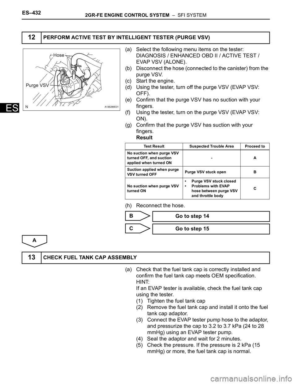
(a) Select the following menu items on the tester:
DIAGNOSIS / ENHANCED OBD II / ACTIVE TEST /
EVAP VSV (ALONE).
(b) Disconnect the hose (connected to the canister) from the
purge VSV.
(c) Start the engine.
(d) Using the tester, turn off the purge VSV (EVAP VSV:
OFF).
(e) Confirm that the purge VSV has no suction with your
fingers.
(f) Using the tester, turn on the purge VSV (EVAP VSV:
ON).
(g) Confirm that the purge VSV has suction with your
fingers.
Result
(h) Reconnect the hose.
B
C
A
(a) Check that the fuel tank cap is correctly installed and
confirm the fuel tank cap meets OEM specification.
HINT:
If an EVAP tester is available, check the fuel tank cap
using the tester.
(1) Tighten the fuel tank cap
(2) Remove the fuel tank cap and install it onto the fuel
tank cap adaptor.
(3) Connect the EVAP tester pump hose to the adaptor,
and pressurize the cap to 3.2 to 3.7 kPa (24 to 28
mmHg) using an EVAP tester pump.
(4) Seal the adaptor and wait for 2 minutes.
(5) Check the pressure. If the pressure is 2 kPa (15
mmHg) or more, the fuel tank cap is normal.
12PERFORM ACTIVE TEST BY INTELLIGENT TESTER (PURGE VSV)
A136286E01
Test Result Suspected Trouble Area Proceed to
No suction when purge VSV
turned OFF, and suction
applied when turned ON-A
Suction applied when purge
VSV turned OFFPurge VSV stuck open B
No suction when purge VSV
turned ON• Purge VSV stuck closed
• Problems with EVAP
hose between purge VSV
and throttle bodyC
Go to step 14
Go to step 15
13CHECK FUEL TANK CAP ASSEMBLY
Page 719 of 3000
2GR-FE ENGINE CONTROL SYSTEM – SFI SYSTEMES–433
ES
Result
A
B
C
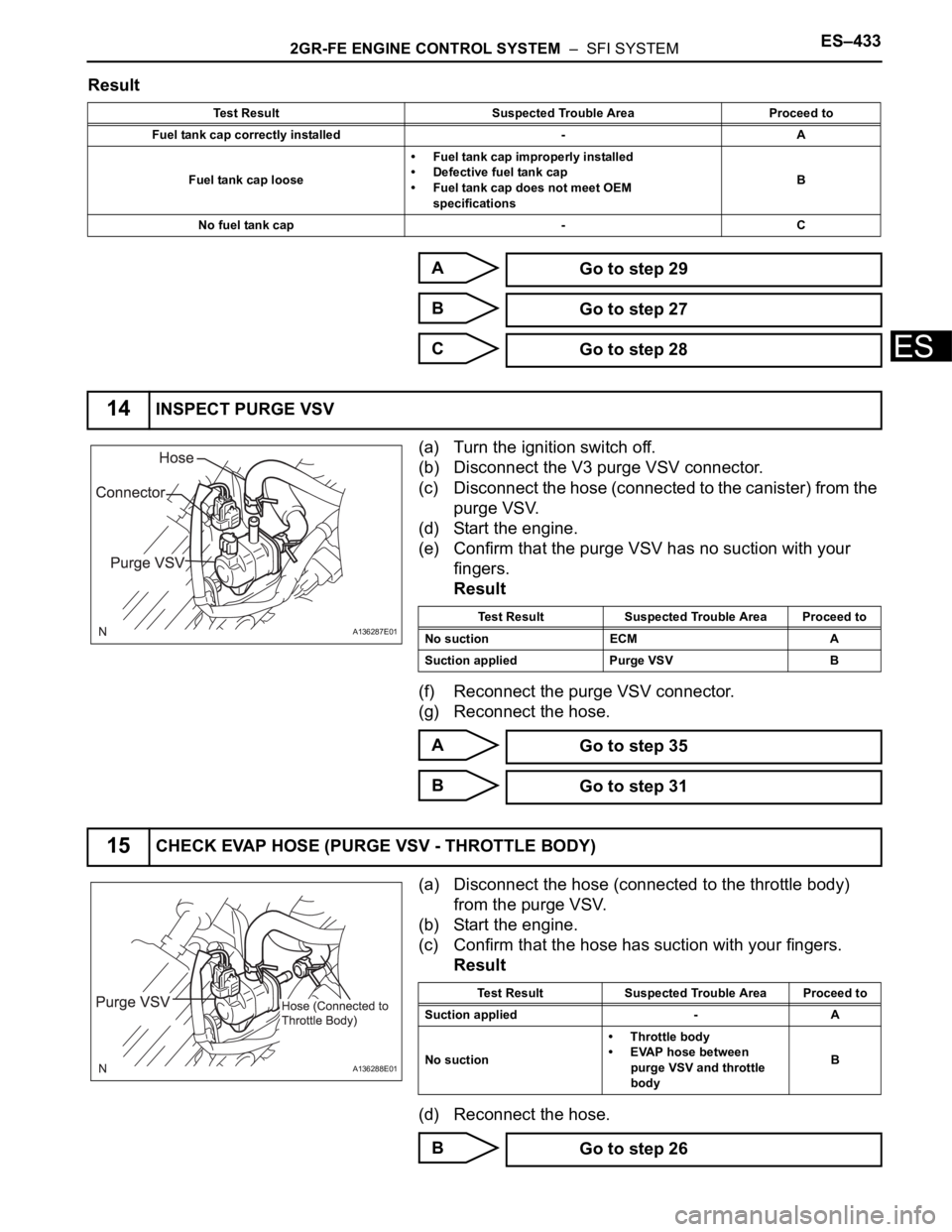
(a) Turn the ignition switch off.
(b) Disconnect the V3 purge VSV connector.
(c) Disconnect the hose (connected to the canister) from the
purge VSV.
(d) Start the engine.
(e) Confirm that the purge VSV has no suction with your
fingers.
Result
(f) Reconnect the purge VSV connector.
(g) Reconnect the hose.
A
B
(a) Disconnect the hose (connected to the throttle body)
from the purge VSV.
(b) Start the engine.
(c) Confirm that the hose has suction with your fingers.
Result
(d) Reconnect the hose.
B
Test Result Suspected Trouble Area Proceed to
Fuel tank cap correctly installed - A
Fuel tank cap loose• Fuel tank cap improperly installed
• Defective fuel tank cap
• Fuel tank cap does not meet OEM
specificationsB
No fuel tank cap - C
Go to step 29
Go to step 27
Go to step 28
14INSPECT PURGE VSV
A136287E01Test Result Suspected Trouble Area Proceed to
No suction ECM A
Suction applied Purge VSV B
Go to step 35
Go to step 31
15CHECK EVAP HOSE (PURGE VSV - THROTTLE BODY)
A136288E01
Test Result Suspected Trouble Area Proceed to
Suction applied - A
No suction• Throttle body
• EVAP hose between
purge VSV and throttle
bodyB
Go to step 26
Page 725 of 3000
2GR-FE ENGINE CONTROL SYSTEM – SFI SYSTEMES–439
ES
A
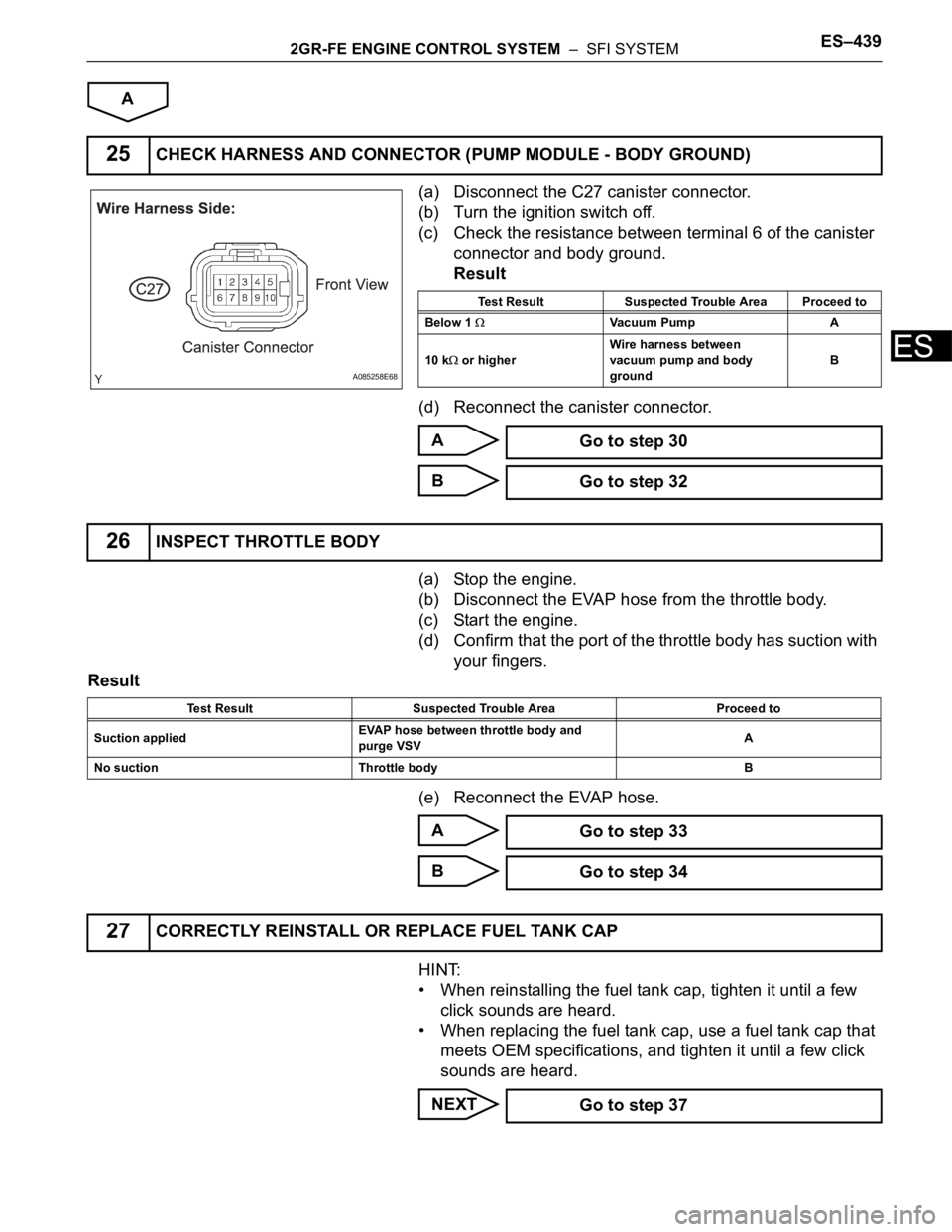
(a) Disconnect the C27 canister connector.
(b) Turn the ignition switch off.
(c) Check the resistance between terminal 6 of the canister
connector and body ground.
Result
(d) Reconnect the canister connector.
A
B
(a) Stop the engine.
(b) Disconnect the EVAP hose from the throttle body.
(c) Start the engine.
(d) Confirm that the port of the throttle body has suction with
your fingers.
Result
(e) Reconnect the EVAP hose.
A
B
HINT:
• When reinstalling the fuel tank cap, tighten it until a few
click sounds are heard.
• When replacing the fuel tank cap, use a fuel tank cap that
meets OEM specifications, and tighten it until a few click
sounds are heard.
NEXT
25CHECK HARNESS AND CONNECTOR (PUMP MODULE - BODY GROUND)
A085258E68
Test Result Suspected Trouble Area Proceed to
Below 1
Vacuum Pump A
10 k
or higherWire harness between
vacuum pump and body
groundB
Go to step 30
Go to step 32
26INSPECT THROTTLE BODY
Test Result Suspected Trouble Area Proceed to
Suction appliedEVAP hose between throttle body and
purge VSVA
No suction Throttle body B
Go to step 33
Go to step 34
27CORRECTLY REINSTALL OR REPLACE FUEL TANK CAP
Go to step 37