2007 TOYOTA SIENNA engine mechanical
[x] Cancel search: engine mechanicalPage 200 of 3000

SERVICE SPECIFICATIONS – 2GR-FE ENGINE MECHANICALSS–13
SS
Main bearing cap x Cylinder block sub-assembly 16 pointed head
1st61 622 45
2nd Turn 90
Turn 90Turn 90
14 mm head 52 525 38
Connecting rod cap x Connecting rod 1st 25 255 18
2nd Turn 90
Turn 90Turn 90
Stud bolt x Cylinder block sub-assembly bolt A 10 102 7
bolt B 17 173 13
Sub-assembly oil nozzle No. 1 x Cylinder block sub-assembly 9.0 92 80 in.*lbf
Camshaft position sensor x Cylinder head cover sub-assembly 10 1027 Part Tightened N*m kgf*cm ft.*lbf
Page 370 of 3000
ES–642GR-FE ENGINE CONTROL SYSTEM – SFI SYSTEM
ES
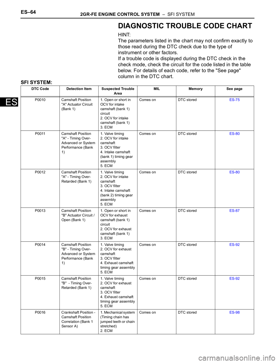
DIAGNOSTIC TROUBLE CODE CHART
HINT:
The parameters listed in the chart may not confirm exactly to
those read during the DTC check due to the type of
instrument or other factors.
If a trouble code is displayed during the DTC check in the
check mode, check the circuit for the code listed in the table
below. For details of each code, refer to the "See page"
column in the DTC chart.
SFI SYSTEM:
DTC Code Detection Item Suspected Trouble
AreaMIL Memory See page
P0010 Camshaft Position
"A" Actuator Circuit
(Bank 1)1. Open or short in
OCV for intake
camshaft (bank 1)
circuit
2. OCV for intake
camshaft (bank 1)
3. ECMComes on DTC storedES-75
P0011 Camshaft Position
"A" - Timing Over-
Advanced or System
Performance (Bank
1)1. Valve timing
2. OCV for intake
camshaft
3. OCV filter
4. Intake camshaft
(bank 1) timing gear
assembly
5. ECMComes on DTC storedES-80
P0012 Camshaft Position
"A" - Timing Over-
Retarded (Bank 1)1. Valve timing
2. OCV for intake
camshaft
3. OCV filter
4. Intake camshaft
(bank 2) timing gear
assembly
5. ECMComes on DTC storedES-80
P0013 Camshaft Position
"B" Actuator Circuit /
Open (Bank 1)1. Open or short in
OCV for exhaust
camshaft (bank 1)
circuit
2. OCV for exhaust
camshaft (bank 1)
3. ECMComes on DTC storedES-87
P0014 Camshaft Position
"B" - Timing Over-
Advanced or System
Performance (Bank
1)1. Valve timing
2. OCV for exhaust
camshaft
3. OCV filter
4. Exhaust camshaft
timing gear assembly
5. ECMComes on DTC storedES-92
P0015 Camshaft Position
"B" - Timing Over-
Retarded (Bank 1)1. Valve timing
2. OCV for exhaust
camshaft
3. OCV filter
4. Exhaust camshaft
timing gear assembly
5. ECMComes on DTC storedES-92
P0016 Crankshaft Position -
Camshaft Position
Correlation (Bank 1
Sensor A)1. Mechanical system
(Timing chain has
jumped teeth or chain
stretched)
2. ECMComes on DTC storedES-98
Page 371 of 3000
2GR-FE ENGINE CONTROL SYSTEM – SFI SYSTEMES–65
ES
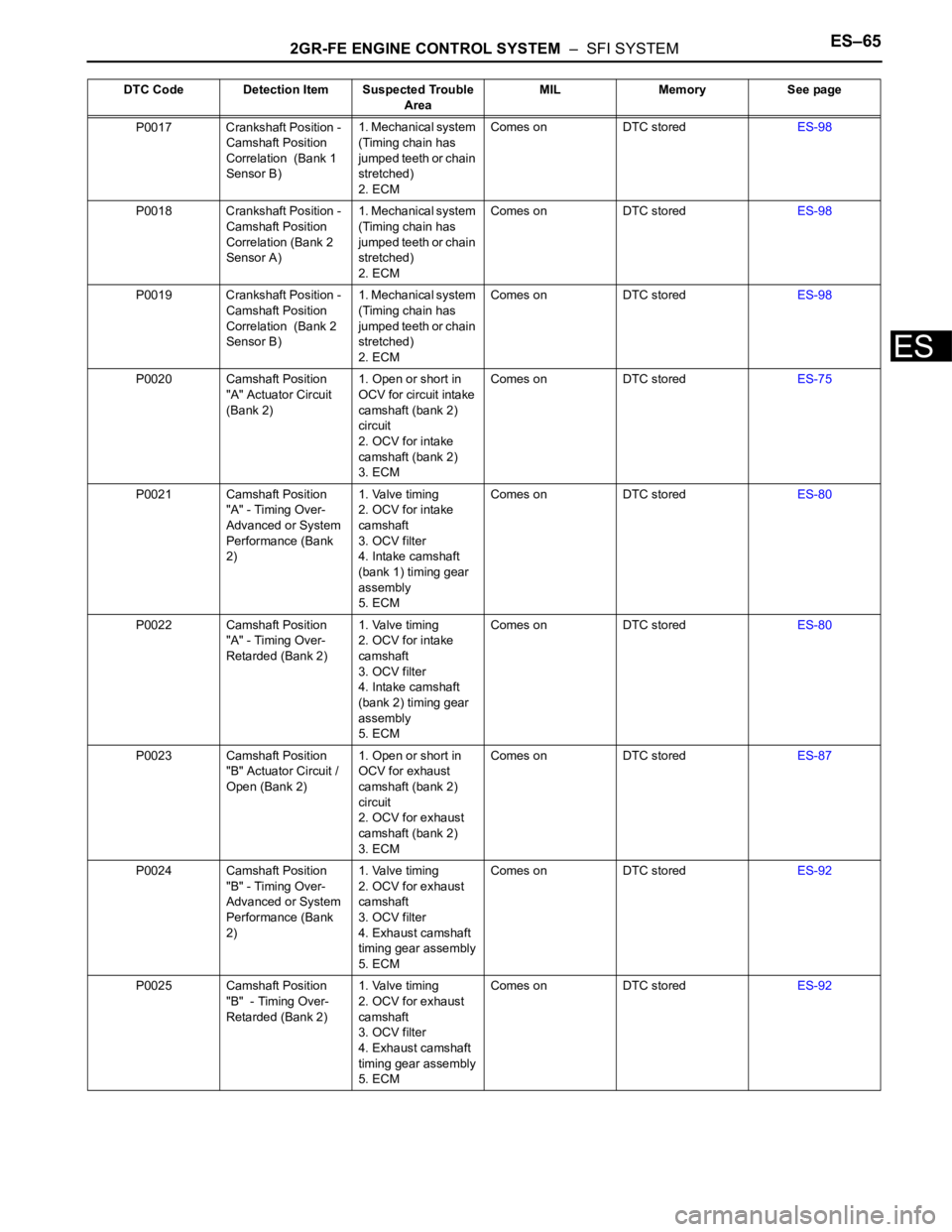
P0017 Crankshaft Position -
Camshaft Position
Correlation (Bank 1
Sensor B)1. Mechanical system
(Timing chain has
jumped teeth or chain
stretched)
2. ECMComes on DTC storedES-98
P0018 Crankshaft Position -
Camshaft Position
Correlation (Bank 2
Sensor A)1. Mechanical system
(Timing chain has
jumped teeth or chain
stretched)
2. ECMComes on DTC storedES-98
P0019 Crankshaft Position -
Camshaft Position
Correlation (Bank 2
Sensor B)1. Mechanical system
(Timing chain has
jumped teeth or chain
stretched)
2. ECMComes on DTC storedES-98
P0020 Camshaft Position
"A" Actuator Circuit
(Bank 2)1. Open or short in
OCV for circuit intake
camshaft (bank 2)
circuit
2. OCV for intake
camshaft (bank 2)
3. ECMComes on DTC storedES-75
P0021 Camshaft Position
"A" - Timing Over-
Advanced or System
Performance (Bank
2)1. Valve timing
2. OCV for intake
camshaft
3. OCV filter
4. Intake camshaft
(bank 1) timing gear
assembly
5. ECMComes on DTC storedES-80
P0022 Camshaft Position
"A" - Timing Over-
Retarded (Bank 2)1. Valve timing
2. OCV for intake
camshaft
3. OCV filter
4. Intake camshaft
(bank 2) timing gear
assembly
5. ECMComes on DTC storedES-80
P0023 Camshaft Position
"B" Actuator Circuit /
Open (Bank 2)1. Open or short in
OCV for exhaust
camshaft (bank 2)
circuit
2. OCV for exhaust
camshaft (bank 2)
3. ECMComes on DTC storedES-87
P0024 Camshaft Position
"B" - Timing Over-
Advanced or System
Performance (Bank
2)1. Valve timing
2. OCV for exhaust
camshaft
3. OCV filter
4. Exhaust camshaft
timing gear assembly
5. ECMComes on DTC storedES-92
P0025 Camshaft Position
"B" - Timing Over-
Retarded (Bank 2)1. Valve timing
2. OCV for exhaust
camshaft
3. OCV filter
4. Exhaust camshaft
timing gear assembly
5. ECMComes on DTC storedES-92 DTC Code Detection Item Suspected Trouble
AreaMIL Memory See page
Page 412 of 3000
ES–1062GR-FE ENGINE CONTROL SYSTEM – SFI SYSTEM
ES
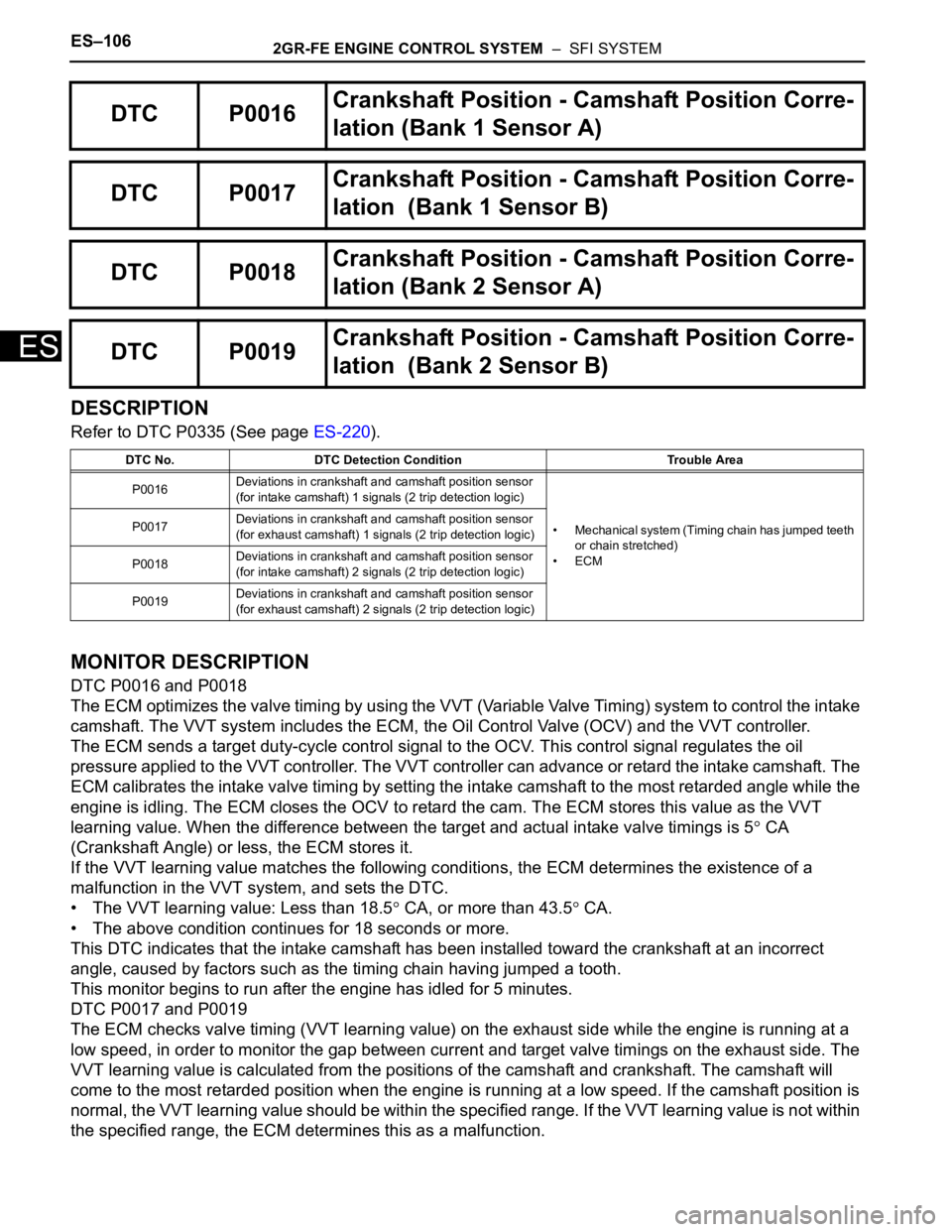
DESCRIPTION
Refer to DTC P0335 (See page ES-220).
MONITOR DESCRIPTION
DTC P0016 and P0018
The ECM optimizes the valve timing by using the VVT (Variable Valve Timing) system to control the intake
camshaft. The VVT system includes the ECM, the Oil Control Valve (OCV) and the VVT controller.
The ECM sends a target duty-cycle control signal to the OCV. This control signal regulates the oil
pressure applied to the VVT controller. The VVT controller can advance or retard the intake camshaft. The
ECM calibrates the intake valve timing by setting the intake camshaft to the most retarded angle while the
engine is idling. The ECM closes the OCV to retard the cam. The ECM stores this value as the VVT
learning value. When the difference between the target and actual intake valve timings is 5
CA
(Crankshaft Angle) or less, the ECM stores it.
If the VVT learning value matches the following conditions, the ECM determines the existence of a
malfunction in the VVT system, and sets the DTC.
• The VVT learning value: Less than 18.5
CA, or more than 43.5 CA.
• The above condition continues for 18 seconds or more.
This DTC indicates that the intake camshaft has been installed toward the crankshaft at an incorrect
angle, caused by factors such as the timing chain having jumped a tooth.
This monitor begins to run after the engine has idled for 5 minutes.
DTC P0017 and P0019
The ECM checks valve timing (VVT learning value) on the exhaust side while the engine is running at a
low speed, in order to monitor the gap between current and target valve timings on the exhaust side. The
VVT learning value is calculated from the positions of the camshaft and crankshaft. The camshaft will
come to the most retarded position when the engine is running at a low speed. If the camshaft position is
normal, the VVT learning value should be within the specified range. If the VVT learning value is not within
the specified range, the ECM determines this as a malfunction.
DTC P0016Crankshaft Position - Camshaft Position Corre-
lation (Bank 1 Sensor A)
DTC P0017Crankshaft Position - Camshaft Position Corre-
lation (Bank 1 Sensor B)
DTC P0018Crankshaft Position - Camshaft Position Corre-
lation (Bank 2 Sensor A)
DTC P0019Crankshaft Position - Camshaft Position Corre-
lation (Bank 2 Sensor B)
DTC No. DTC Detection Condition Trouble Area
P0016Deviations in crankshaft and camshaft position sensor
(for intake camshaft) 1 signals (2 trip detection logic)
• Mechanical system (Timing chain has jumped teeth
or chain stretched)
•ECM P0017Deviations in crankshaft and camshaft position sensor
(for exhaust camshaft) 1 signals (2 trip detection logic)
P0018Deviations in crankshaft and camshaft position sensor
(for intake camshaft) 2 signals (2 trip detection logic)
P0019Deviations in crankshaft and camshaft position sensor
(for exhaust camshaft) 2 signals (2 trip detection logic)
Page 537 of 3000
2GR-FE ENGINE CONTROL SYSTEM – SFI SYSTEMES–231
ES
INSPECTION PROCEDURE
HINT:
• If no problem is found by this diagnostic troubleshooting procedure, troubleshoot the engine
mechanical systems.
• Check the engine speed. The engine speed can be checked by using the intelligent tester. Perform the
following procedure:
(a) Connect the intelligent tester to the DLC3.
(b) Start the engine.
(c) Turn the tester on.
(d) Select the following menu items: DIAGNOSIS / ENHANCED OBD II / DATA LIST / PRIMARY /
ENGINE SPD.
The engine speed may be indicated as zero despite the engine revolving normally. This is caused
by a lack of NE signals from the Crankshaft Position (CKP) sensor. Alternatively, the engine speed
may be indicated as lower than the actual engine speed, if the CKP sensor voltage output is
insufficient.
• Read freeze frame data using the intelligent tester. The ECM records vehicle and driving condition
information as freeze frame data the moment a DTC is stored. When troubleshooting, freeze frame
data can be helpful in determining whether the vehicle was running or stopped, whether the engine
was warmed up or not, whether the air-fuel ratio was lean or rich, as well as other data recorded at the
time of a malfunction.
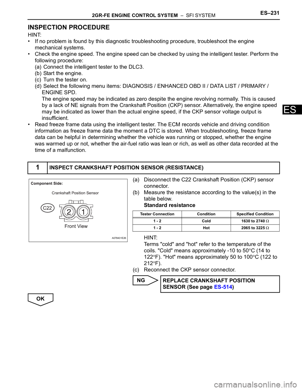
(a) Disconnect the C22 Crankshaft Position (CKP) sensor
connector.
(b) Measure the resistance according to the value(s) in the
table below.
Standard resistance
HINT:
Terms "cold" and "hot" refer to the temperature of the
coils. "Cold" means approximately -10 to 50
C (14 to
122
F). "Hot" means approximately 50 to 100C (122 to
212
F).
(c) Reconnect the CKP sensor connector.
NG
OK
1INSPECT CRANKSHAFT POSITION SENSOR (RESISTANCE)
A078431E26
Tester Connection Condition Specified Condition
1 - 2 Cold 1630 to 2740
1 - 2 Hot 2065 to 3225
REPLACE CRANKSHAFT POSITION
SENSOR (See page ES-514)
Page 860 of 3000
2GR-FE ENGINE MECHANICAL – ENGINE ASSEMBLYEM–43
EM
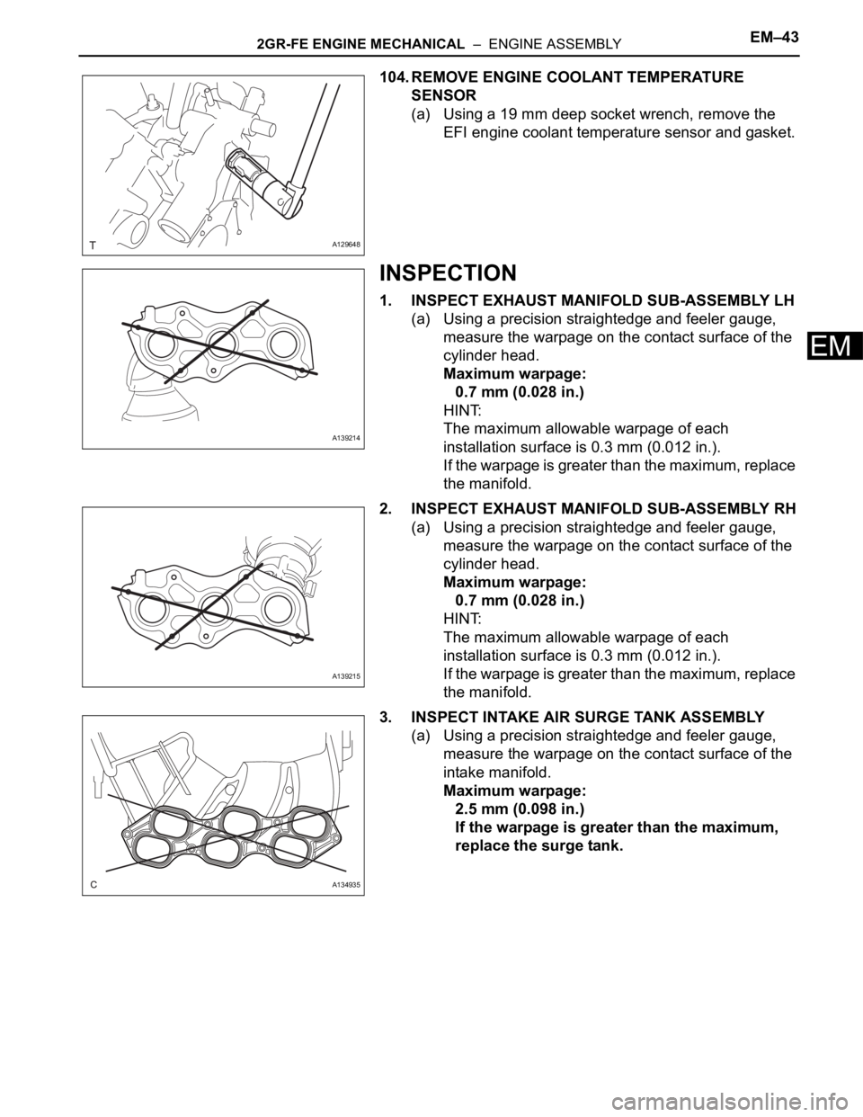
104. REMOVE ENGINE COOLANT TEMPERATURE
SENSOR
(a) Using a 19 mm deep socket wrench, remove the
EFI engine coolant temperature sensor and gasket.
INSPECTION
1. INSPECT EXHAUST MANIFOLD SUB-ASSEMBLY LH
(a) Using a precision straightedge and feeler gauge,
measure the warpage on the contact surface of the
cylinder head.
Maximum warpage:
0.7 mm (0.028 in.)
HINT:
The maximum allowable warpage of each
installation surface is 0.3 mm (0.012 in.).
If the warpage is greater than the maximum, replace
the manifold.
2. INSPECT EXHAUST MANIFOLD SUB-ASSEMBLY RH
(a) Using a precision straightedge and feeler gauge,
measure the warpage on the contact surface of the
cylinder head.
Maximum warpage:
0.7 mm (0.028 in.)
HINT:
The maximum allowable warpage of each
installation surface is 0.3 mm (0.012 in.).
If the warpage is greater than the maximum, replace
the manifold.
3. INSPECT INTAKE AIR SURGE TANK ASSEMBLY
(a) Using a precision straightedge and feeler gauge,
measure the warpage on the contact surface of the
intake manifold.
Maximum warpage:
2.5 mm (0.098 in.)
If the warpage is greater than the maximum,
replace the surge tank.
A129648
A139214
A139215
A134935
Page 861 of 3000
EM–442GR-FE ENGINE MECHANICAL – ENGINE ASSEMBLY
EM
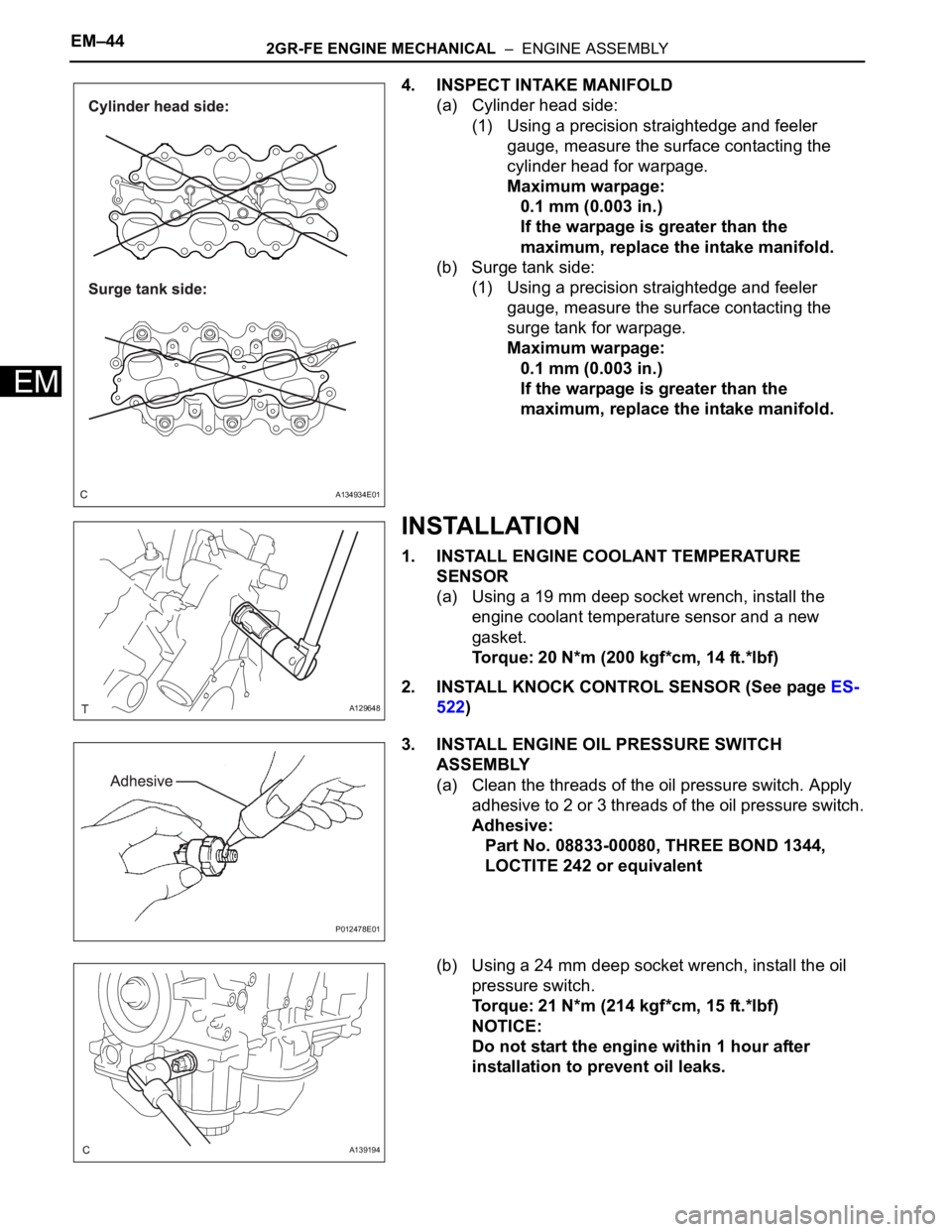
4. INSPECT INTAKE MANIFOLD
(a) Cylinder head side:
(1) Using a precision straightedge and feeler
gauge, measure the surface contacting the
cylinder head for warpage.
Maximum warpage:
0.1 mm (0.003 in.)
If the warpage is greater than the
maximum, replace the intake manifold.
(b) Surge tank side:
(1) Using a precision straightedge and feeler
gauge, measure the surface contacting the
surge tank for warpage.
Maximum warpage:
0.1 mm (0.003 in.)
If the warpage is greater than the
maximum, replace the intake manifold.
INSTALLATION
1. INSTALL ENGINE COOLANT TEMPERATURE
SENSOR
(a) Using a 19 mm deep socket wrench, install the
engine coolant temperature sensor and a new
gasket.
Torque: 20 N*m (200 kgf*cm, 14 ft.*lbf)
2. INSTALL KNOCK CONTROL SENSOR (See page ES-
522)
3. INSTALL ENGINE OIL PRESSURE SWITCH
ASSEMBLY
(a) Clean the threads of the oil pressure switch. Apply
adhesive to 2 or 3 threads of the oil pressure switch.
Adhesive:
Part No. 08833-00080, THREE BOND 1344,
LOCTITE 242 or equivalent
(b) Using a 24 mm deep socket wrench, install the oil
pressure switch.
Torque: 21 N*m (214 kgf*cm, 15 ft.*lbf)
NOTICE:
Do not start the engine within 1 hour after
installation to prevent oil leaks.
A134934E01
A129648
P012478E01
A139194
Page 862 of 3000
2GR-FE ENGINE MECHANICAL – ENGINE ASSEMBLYEM–45
EM
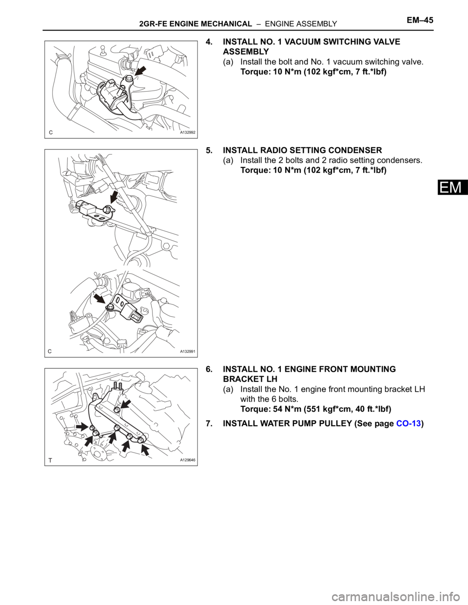
4. INSTALL NO. 1 VACUUM SWITCHING VALVE
ASSEMBLY
(a) Install the bolt and No. 1 vacuum switching valve.
Torque: 10 N*m (102 kgf*cm, 7 ft.*lbf)
5. INSTALL RADIO SETTING CONDENSER
(a) Install the 2 bolts and 2 radio setting condensers.
Torque: 10 N*m (102 kgf*cm, 7 ft.*lbf)
6. INSTALL NO. 1 ENGINE FRONT MOUNTING
BRACKET LH
(a) Install the No. 1 engine front mounting bracket LH
with the 6 bolts.
Torque: 54 N*m (551 kgf*cm, 40 ft.*lbf)
7. INSTALL WATER PUMP PULLEY (See page CO-13)
A132992
A132991
A129646