Page 573 of 3000
ES–2802GR-FE ENGINE CONTROL SYSTEM – SFI SYSTEM
ES
WIRING DIAGRAM
A136107E03
Page 585 of 3000

ES–2922GR-FE ENGINE CONTROL SYSTEM – SFI SYSTEM
ES
TYPICAL MALFUNCTION THRESHOLDS
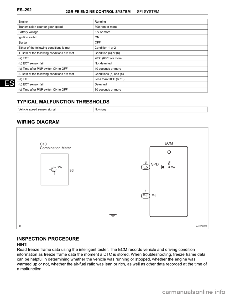
WIRING DIAGRAM
INSPECTION PROCEDURE
HINT:
Read freeze frame data using the intelligent tester. The ECM records vehicle and driving condition
information as freeze frame data the moment a DTC is stored. When troubleshooting, freeze frame data
can be helpful in determining whether the vehicle was running or stopped, whether the engine was
warmed up or not, whether the air-fuel ratio was lean or rich, as well as other data recorded at the time of
a malfunction.
Engine Running
Transmission counter gear speed 300 rpm or more
Battery voltage 8 V or more
Ignition switch ON
Starter OFF
Either of the following conditions is met Condition 1 or 2
1. Both of the following conditions are met Condition (a) or (b)
(a) ECT 20
C (68F) or more
(b) ECT sensor fail Not detected
(c) Time after PNP switch ON to OFF 10 seconds or more
2. Both of the following conditions are met Conditions (a) and (b)
(a) ECT Less than 20
C (68F)
(b) ECT sensor fail Detected
(c) Time after PNP switch ON to OFF 30 seconds or more
Vehicle speed sensor signal No signal
A122761E09
Page 590 of 3000
2GR-FE ENGINE CONTROL SYSTEM – SFI SYSTEMES–297
ES
TYPICAL MALFUNCTION THRESHOLDS
WIRING DIAGRAM
INSPECTION PROCEDURE
HINT:
Read freeze frame data using the intelligent tester. The ECM records vehicle and driving condition
information as freeze frame data the moment a DTC is stored. When troubleshooting, freeze frame data
can be helpful in determining whether the vehicle was running or stopped, whether the engine was
warmed up or not, whether the air-fuel ratio was lean or rich, as well as other data recorded at the time of
a malfunction.
(a) Check whether the stop lights turn on and off normally
when the brake pedal is depressed and released.
OK:
Stop lights turn on when brake pedal is depressed.
NG
OK
Switch status ON stuck Remain ON during GO and STOP 5 times
1CHECK OPERATION OF STOP LIGHT
A162496E02
GO TO TAILLIGHT RELAY CIRCUIT (See
page LI-114)
Page 609 of 3000

ES–3162GR-FE ENGINE CONTROL SYSTEM – SFI SYSTEM
ES
MONITOR DESCRIPTION
The battery supplies electricity to the ECM even when the ignition switch is off. This power allows the
ECM to store data such as DTC history, freeze frame data and fuel trim values. If the battery voltage falls
below a minimum level, these memories are cleared and the ECM determines that there is a malfunction
in the power supply circuit. When the engine is next started, the ECM illuminates the MIL and sets the
DTC.
HINT:
If DTC P0560 is set, the ECM does not store other DTCs.
MONITOR STRATEGY
TYPICAL ENABLING CONDITIONS
TYPICAL MALFUNCTION THRESHOLDS
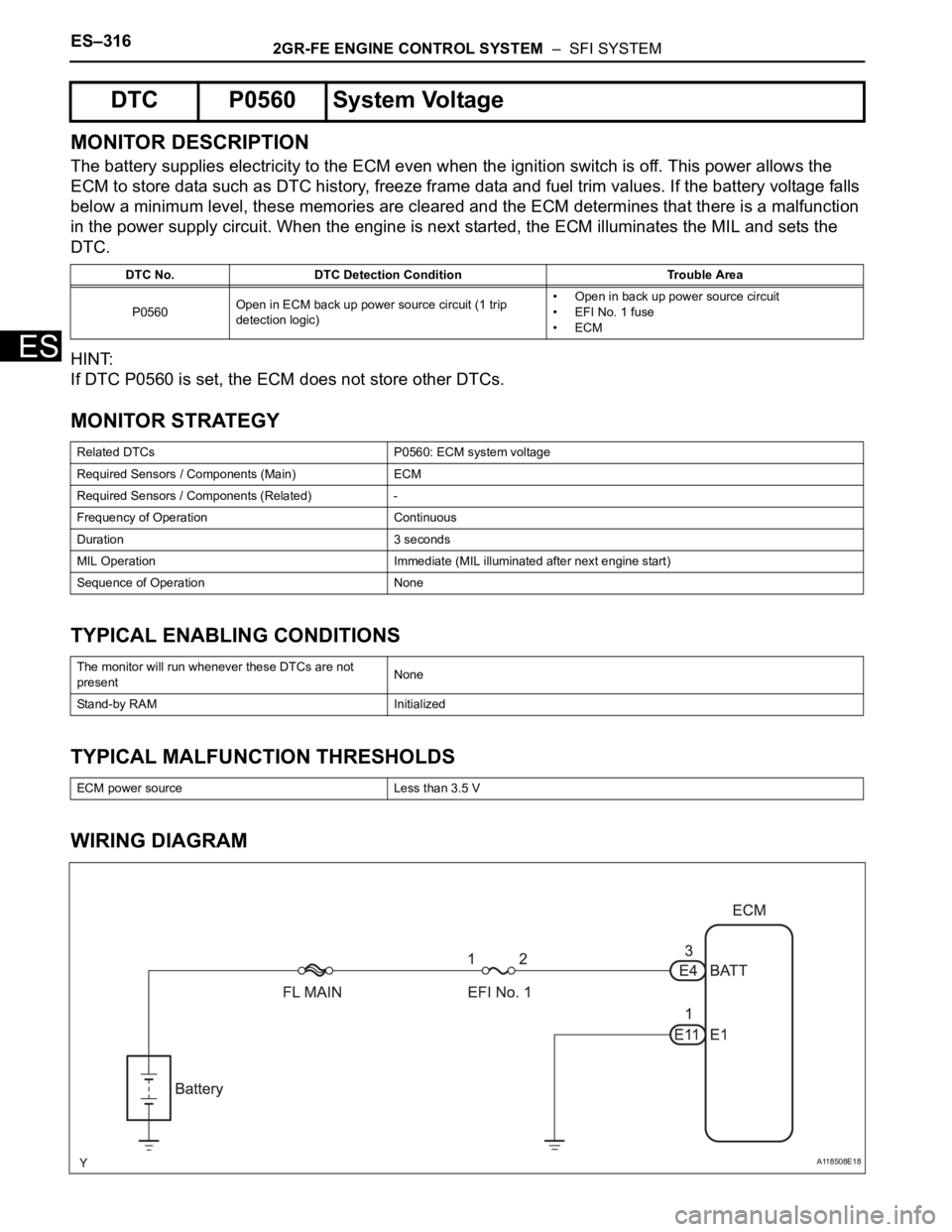
WIRING DIAGRAM
DTC P0560 System Voltage
DTC No. DTC Detection Condition Trouble Area
P0560Open in ECM back up power source circuit (1 trip
detection logic)• Open in back up power source circuit
• EFI No. 1 fuse
•ECM
Related DTCs P0560: ECM system voltage
Required Sensors / Components (Main) ECM
Required Sensors / Components (Related) -
Frequency of Operation Continuous
Duration 3 seconds
MIL Operation Immediate (MIL illuminated after next engine start)
Sequence of Operation None
The monitor will run whenever these DTCs are not
presentNone
Stand-by RAM Initialized
ECM power source Less than 3.5 V
A118508E18
Page 621 of 3000
ES–3282GR-FE ENGINE CONTROL SYSTEM – SFI SYSTEM
ES
WIRING DIAGRAM
INSPECTION PROCEDURE
HINT:
• The following troubleshooting flowchart is based on the premise that the engine is cranked normally. If
the engine will not crank, proceed to the problem symptoms table (See page ES-27).
A162043E02
Page 629 of 3000

ES–3362GR-FE ENGINE CONTROL SYSTEM – SFI SYSTEM
ES
DESCRIPTION
The park/neutral position switch detects the shift lever position and sends signals to the ECM.
HINT:
After confirming DTC P0705, use the intelligent tester to confirm the PNP switch signal in the ALL menu
(to reach the ALL menu: DIAGNOSIS / ENHANCED OBD II / DATA LIST / ALL).
WIRING DIAGRAM
Refer to DTC P0705 for 2WD model (See page AX-40) or 4WD model (See page AX-40).
INSPECTION PROCEDURE
Refer to DTC P0705 for 2WD model (See page AX-41) or 4WD model (See page AX-41).
HINT:
Read freeze frame data using the intelligent tester or OBD II scan tool. The ECM records vehicle and
driving condition information as freeze frame data the moment a DTC is stored. When troubleshooting,
freeze frame data can help determine if the vehicle was running or stopped, if the engine was warmed up
or not, if the air-fuel ratio was LEAN or RICH, and other data from the time the malfunction occurred.
DTC P0705Transmission Range Sensor Circuit Malfunc-
tion (PRNDL Input)
DTC No. DTC Detection Condition Trouble Area
P0705(A) Any 2 or more signals of the following are ON
simultaneously (2-trip detection logic)
• P input signal is ON.
• N input signal is ON.
• R input signal is ON.
• D input signal is ON.
(B) Any 2 ore more signals of the following are ON
simultaneously (2-trip detection logic)
• NSW input signal is ON.
• R input signal is ON.
• D input signal is ON.
(C) Any of following conditions is met for 2.0 sec. or more in
the S position (2-trip detection logic).
• NSW input signal is ON.
• P input signal is ON.
• N input signal is ON.
• R input signal is ON.
(D) All switches are OFF simultaneously for NSW, P, R, N and
D.• Open or short in park/neutral position switch circuit
• Park/neutral position switch
•ECM
Page 632 of 3000

2GR-FE ENGINE CONTROL SYSTEM – SFI SYSTEMES–339
ES
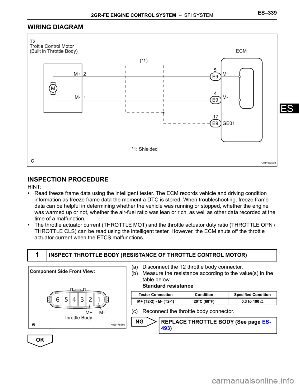
WIRING DIAGRAM
INSPECTION PROCEDURE
HINT:
• Read freeze frame data using the intelligent tester. The ECM records vehicle and driving condition
information as freeze frame data the moment a DTC is stored. When troubleshooting, freeze frame
data can be helpful in determining whether the vehicle was running or stopped, whether the engine
was warmed up or not, whether the air-fuel ratio was lean or rich, as well as other data recorded at the
time of a malfunction.
• The throttle actuator current (THROTTLE MOT) and the throttle actuator duty ratio (THROTTLE OPN /
THROTTLE CLS) can be read using the intelligent tester. However, the ECM shuts off the throttle
actuator current when the ETCS malfunctions.
(a) Disconnect the T2 throttle body connector.
(b) Measure the resistance according to the value(s) in the
table below.
Standard resistance
(c) Reconnect the throttle body connector.
NG
OK
1INSPECT THROTTLE BODY (RESISTANCE OF THROTTLE CONTROL MOTOR)
G041063E08
A059778E56
Tester Connection Condition Specified Condition
M+ (T2-2) - M- (T2-1) 20
C (68F) 0.3 to 100
REPLACE THROTTLE BODY (See page ES-
493)
Page 635 of 3000

ES–3422GR-FE ENGINE CONTROL SYSTEM – SFI SYSTEM
ES
*: System guard set when following conditions met
TYPICAL MALFUNCTION THRESHOLDS
P2111 (Throttle actuator stuck open):
P2112 (Throttle actuator stuck closed):
FA I L - S A F E
When either of these DTCs, as well as other DTCs relating to ETCS (Electronic Throttle Control System)
malfunctions, is set, the ECM enters fail-safe mode. During fail-safe mode, the ECM cuts the current to
the throttle actuator off, and the throttle valve is returned to a 6
throttle angle by the return spring. The
ECM then adjusts the engine output by controlling the fuel injection (intermittent fuel-cut) and ignition
timing, in accordance with the accelerator pedal opening angle, to allow the vehicle to continue at a
minimal speed.
If the accelerator pedal is depressed slowly, the vehicle can be driven slowly.
Fail-safe mode continues until a pass condition is detected, and the ignition switch is then turned off.
WIRING DIAGRAM
Refer to DTC P2102 (See page ES-331).
INSPECTION PROCEDURE
HINT:
Read freeze frame data using the intelligent tester. The ECM records vehicle and driving condition
information as freeze frame data the moment a DTC is stored. When troubleshooting, freeze frame data
can be helpful in determining whether the vehicle was running or stopped, whether the engine was
warmed up or not, whether the air-fuel ratio was lean or rich, as well as other data recorded at the time of
a malfunction.
(a) Connect the intelligent tester to the DLC3.
(b) Turn the ignition switch to the ON position.
(c) Turn the tester on.
(d) Select the following menu items: DIAGNOSIS /
ENHANCED OBD II / DTC INFO / CURRENT CODES.
(e) Read the DTCs.
Result
Throttle actuator open duty-cycle 80% or more
Throttle actuator ON
Throttle actuator duty calculation Executing
Throttle position sensor Fail determined
Throttle actuator current-cut operation Not executing
Throttle actuator power supply 4 V or more
Throttle actuator Fail determined
TP sensor voltage change No change
TP sensor voltage change No change
1CHECK ANY OTHER DTCS OUTPUT (IN ADDITION TO DTC P2111 OR P2112)
Display (DTC Output) Proceed to
P2111 or P2112 A
P2111 or P2112 and other DTCs B