2007 TOYOTA SIENNA wiring
[x] Cancel search: wiringPage 854 of 3000
MULTIPLEX COMMUNICATION – MULTIPLEX COMMUNICATION SYSTEMMP–11
MP
If the result is not as specified, there may be a
malfunction on the wire harness side.
(c) Measure the resistance between the specified
terminals on the wire harness side connector.
If the result is not as specified, there may be a
malfunction on the wire harness side.
8. POWER SLIDE DOOR ECU LH
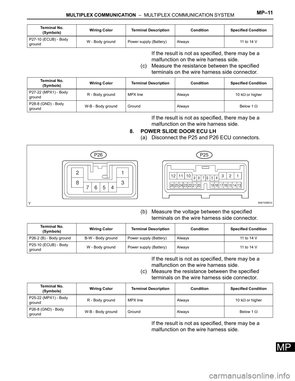
(a) Disconnect the P25 and P26 ECU connectors.
(b) Measure the voltage between the specified
terminals on the wire harness side connector.
If the result is not as specified, there may be a
malfunction on the wire harness side.
(c) Measure the resistance between the specified
terminals on the wire harness side connector.
If the result is not as specified, there may be a
malfunction on the wire harness side.
P27-10 (ECUB) - Body
groundW - Body ground Power supply (Battery) Always 11 to 14 V Terminal No.
(Symbols)Wiring Color Terminal Description Condition Specified Condition
Terminal No.
(Symbols)Wiring Color Terminal Description Condition Specified Condition
P27-22 (MPX1) - Body
groundR - Body ground MPX line Always 10 k
or higher
P28-8 (GND) - Body
groundW-B - Body ground Ground Always Below 1
B067256E03
Terminal No.
(Symbols)Wiring Color Terminal Description Condition Specified Condition
P26-2 (B) - Body ground B-W - Body ground Power supply (Battery) Always 11 to 14 V
P25-10 (ECUB) - Body
groundW - Body ground Power supply (Battery) Always 11 to 14 V
Terminal No.
(Symbols)Wiring Color Terminal Description Condition Specified Condition
P25-22 (MPX1) - Body
groundR - Body ground MPX line Always 10 k
or higher
P26-8 (GND) - Body
groundW-B - Body ground Ground Always Below 1
Page 855 of 3000
MP–12MULTIPLEX COMMUNICATION – MULTIPLEX COMMUNICATION SYSTEM
MP
9. POWER BACK DOOR ECU
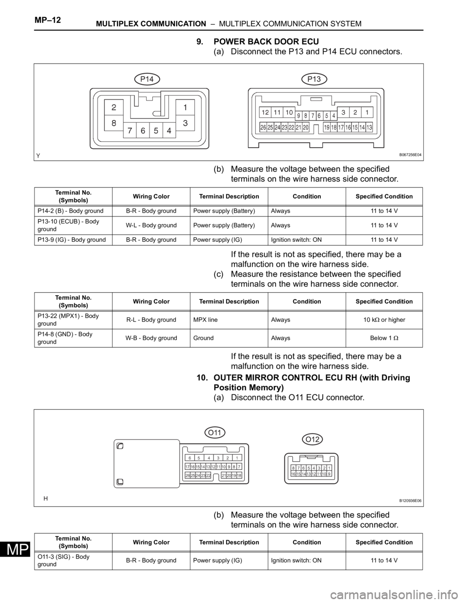
(a) Disconnect the P13 and P14 ECU connectors.
(b) Measure the voltage between the specified
terminals on the wire harness side connector.
If the result is not as specified, there may be a
malfunction on the wire harness side.
(c) Measure the resistance between the specified
terminals on the wire harness side connector.
If the result is not as specified, there may be a
malfunction on the wire harness side.
10. OUTER MIRROR CONTROL ECU RH (with Driving
Position Memory)
(a) Disconnect the O11 ECU connector.
(b) Measure the voltage between the specified
terminals on the wire harness side connector.
B067256E04
Te r m i n a l N o .
(Symbols)Wiring Color Terminal Description Condition Specified Condition
P14-2 (B) - Body ground B-R - Body ground Power supply (Battery) Always 11 to 14 V
P13-10 (ECUB) - Body
groundW-L - Body ground Power supply (Battery) Always 11 to 14 V
P13-9 (IG) - Body ground B-R - Body ground Power supply (IG) Ignition switch: ON 11 to 14 V
Te r m i n a l N o .
(Symbols)Wiring Color Terminal Description Condition Specified Condition
P13-22 (MPX1) - Body
groundR-L - Body ground MPX line Always 10 k
or higher
P14-8 (GND) - Body
groundW-B - Body ground Ground Always Below 1
B120936E06
Te r m i n a l N o .
(Symbols)Wiring Color Terminal Description Condition Specified Condition
O11-3 (SIG) - Body
groundB-R - Body ground Power supply (IG) Ignition switch: ON 11 to 14 V
Page 856 of 3000
MULTIPLEX COMMUNICATION – MULTIPLEX COMMUNICATION SYSTEMMP–13
MP
If the result is not as specified, there may be a
malfunction on the wire harness side.
(c) Measure the resistance between the specified
terminals on the wire harness side connector.
If the result is not as specified, there may be a
malfunction on the wire harness side.
11. OUTER MIRROR CONTROL ECU LH (with Driving
Position Memory)
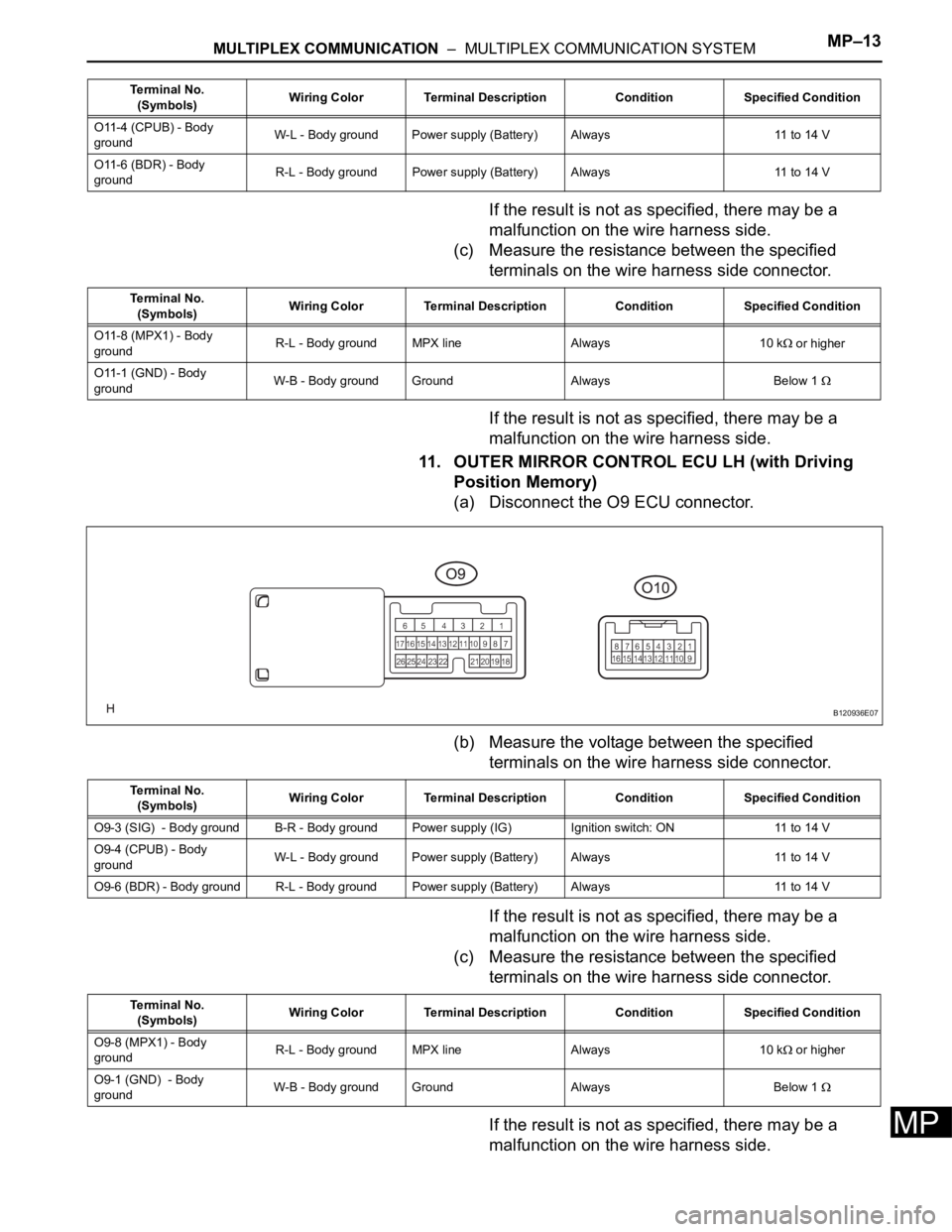
(a) Disconnect the O9 ECU connector.
(b) Measure the voltage between the specified
terminals on the wire harness side connector.
If the result is not as specified, there may be a
malfunction on the wire harness side.
(c) Measure the resistance between the specified
terminals on the wire harness side connector.
If the result is not as specified, there may be a
malfunction on the wire harness side.
O11-4 (CPUB) - Body
groundW-L - Body ground Power supply (Battery) Always 11 to 14 V
O11-6 (BDR) - Body
groundR-L - Body ground Power supply (Battery) Always 11 to 14 V Terminal No.
(Symbols)Wiring Color Terminal Description Condition Specified Condition
Terminal No.
(Symbols)Wiring Color Terminal Description Condition Specified Condition
O11-8 (MPX1) - Body
groundR-L - Body ground MPX line Always 10 k
or higher
O11-1 (GND) - Body
groundW-B - Body ground Ground Always Below 1
B120936E07
Terminal No.
(Symbols)Wiring Color Terminal Description Condition Specified Condition
O9-3 (SIG) - Body ground B-R - Body ground Power supply (IG) Ignition switch: ON 11 to 14 V
O9-4 (CPUB) - Body
groundW-L - Body ground Power supply (Battery) Always 11 to 14 V
O9-6 (BDR) - Body ground R-L - Body ground Power supply (Battery)Always 11 to 14 V
Terminal No.
(Symbols)Wiring Color Terminal Description Condition Specified Condition
O9-8 (MPX1) - Body
groundR-L - Body ground MPX line Always 10 k
or higher
O9-1 (GND) - Body
groundW-B - Body ground Ground Always Below 1
Page 994 of 3000
2GR-FE ENGINE MECHANICAL – ENGINE ASSEMBLYEM–35
EM
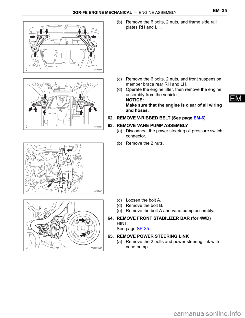
(b) Remove the 6 bolts, 2 nuts, and frame side rail
plates RH and LH.
(c) Remove the 6 bolts, 2 nuts, and front suspension
member brace rear RH and LH.
(d) Operate the engine lifter, then remove the engine
assembly from the vehicle.
NOTICE:
Make sure that the engine is clear of all wiring
and hoses.
62. REMOVE V-RIBBED BELT (See page EM-6)
63. REMOVE VANE PUMP ASSEMBLY
(a) Disconnect the power steering oil pressure switch
connector.
(b) Remove the 2 nuts.
(c) Loosen the bolt A.
(d) Remove the bolt B.
(e) Remove the bolt A and vane pump assembly.
64. REMOVE FRONT STABILIZER BAR (for 4WD)
HINT:
See page SP-35.
65. REMOVE POWER STEERING LINK
(a) Remove the 2 bolts and power steering link with
vane pump.
A162364
A162363
A155024
A139216E01
Page 1117 of 3000
2GR-FE FUEL – FUEL SYSTEMFU–7
FU
ON-VEHICLE INSPECTION
1. INSPECT FOR FUEL PUMP OPERATION AND FUEL
LEAK
(a) Check fuel pump operation.
(1) Connect the intelligent tester to the DLC3.
(2) Turn the engine switch on (IG) and push the
intelligent tester main switch on.
NOTICE:
Do not start the engine.
(3) Select the following menu items: DIAGNOSIS /
ENHANCED OBD II / ACTIVE TEST / FUEL
PUMP / SPD.
(4) Check for pressure in the fuel inlet tube from
the fuel line. Check that sound of fuel flowing in
the fuel tank can be heard. If no sound can be
heard, check the integration relay, fuel pump,
ECM and wiring connector.
(b) Check for fuel leaks (*1).
(1) Check that there are no fuel leaks anywhere on
the system after performing maintenance. If
there is a fuel leak, repair or replace parts as
necessary.
(c) Turn the engine switch off.
(d) Disconnect the intelligent tester from the DLC3.
2. CHECK FUEL PRESSURE
(a) Discharge the fuel system pressure (See page FU-
1).
(b) Using a voltmeter, measure the battery voltage.
Standard voltage:
11 to 14 V
(c) Disconnect the cable from the negative (-) battery
terminal.
(d) Disconnect the fuel hose from the fuel main tube
(See page FU-1).
Page 1126 of 3000
2GR-FE FUEL – FUEL SYSTEMFU–7
FU
ON-VEHICLE INSPECTION
1. INSPECT FOR FUEL PUMP OPERATION AND FUEL
LEAK
(a) Check fuel pump operation.
(1) Connect the intelligent tester to the DLC3.
(2) Turn the engine switch on (IG) and push the
intelligent tester main switch on.
NOTICE:
Do not start the engine.
(3) Select the following menu items: DIAGNOSIS /
ENHANCED OBD II / ACTIVE TEST / FUEL
PUMP / SPD.
(4) Check for pressure in the fuel inlet tube from
the fuel line. Check that sound of fuel flowing in
the fuel tank can be heard. If no sound can be
heard, check the integration relay, fuel pump,
ECM and wiring connector.
(b) Check for fuel leaks (*1).
(1) Check that there are no fuel leaks anywhere on
the system after performing maintenance. If
there is a fuel leak, repair or replace parts as
necessary.
(c) Turn the engine switch off.
(d) Disconnect the intelligent tester from the DLC3.
2. CHECK FUEL PRESSURE
(a) Discharge the fuel system pressure (See page FU-
1).
(b) Using a voltmeter, measure the battery voltage.
Standard voltage:
11 to 14 V
(c) Disconnect the cable from the negative (-) battery
terminal.
(d) Disconnect the fuel hose from the fuel main tube
(See page FU-1).
Page 1316 of 3000
2GR-FE IGNITION – IGNITION COIL AND SPARK PLUGIG–7
IG
(3) Check the spark plug (See page EM-1).
Result
(4) Check the power supply to the ignition coil.
1. Turn the ignition switch to the ON position.
2. Check that there is battery voltage at the
ignition coil positive (+) terminal.
Result
(5) Measure the resistance of the crankshaft
position sensor (See page ES-514).
Result
(6) Check the IGT signal from the ECM (See page
ES-233)
Result
(e) Using a 16 mm (0.63 in.) plug wrench, install the
spark plugs.
Torque: 18 N*m (184 kgf*cm, 13 ft.*lbf)
(f) Connect the 6 fuel injector connectors.
(g) Install the ignition coil assembly (See page IG-10).
2. INSPECT SPARK PLUG
NOTICE:
• Never use a wire brush for cleaning.
• Never attempt to adjust the electrode gap on a
used spark plug.
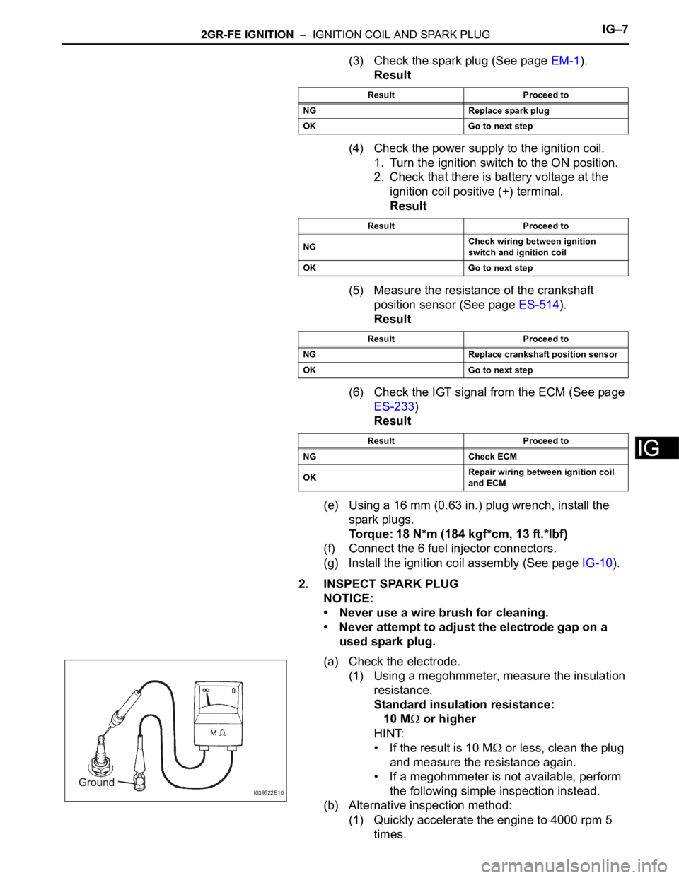
(a) Check the electrode.
(1) Using a megohmmeter, measure the insulation
resistance.
Standard insulation resistance:
10 M
or higher
HINT:
• If the result is 10 M
or less, clean the plug
and measure the resistance again.
• If a megohmmeter is not available, perform
the following simple inspection instead.
(b) Alternative inspection method:
(1) Quickly accelerate the engine to 4000 rpm 5
times.
Result Proceed to
NG Replace spark plug
OK Go to next step
Result Proceed to
NGCheck wiring between ignition
switch and ignition coil
OK Go to next step
Result Proceed to
NG Replace crankshaft position sensor
OK Go to next step
Result Proceed to
NG Check ECM
OKRepair wiring between ignition coil
and ECM
I039522E10
Page 1342 of 3000
2GR-FE CHARGING – CHARGING SYSTEMCH–7
CH
(b) Check that the belt fits properly in the ribbed
grooves.
HINT:
Check with your hand to confirm that the belt has
not slipped out of the groove on the bottom of the
pulley.
If it has slipped out, replace the V-ribbed belt. Install
a new V-ribbed belt correctly.
7. INSPECT GENERATOR WIRING
(a) Visually check the generator wiring.
(1) Check that the wiring is in good condition.
8. CHECK FOR ABNORMAL NOISES
(a) Listen for abnormal noises from the generator.
(1) Check that no abnormal noises are heard from
the generator while the engine is running.
9. CHECK CHARGE WARNING LIGHT CIRCUIT
(a) Turn the ignition switch to the ON position. Check
that the charge warning light comes on.
(b) Start the engine and check that the light goes off.
If the light does not operate as specified,
troubleshoot the charge warning light circuit.
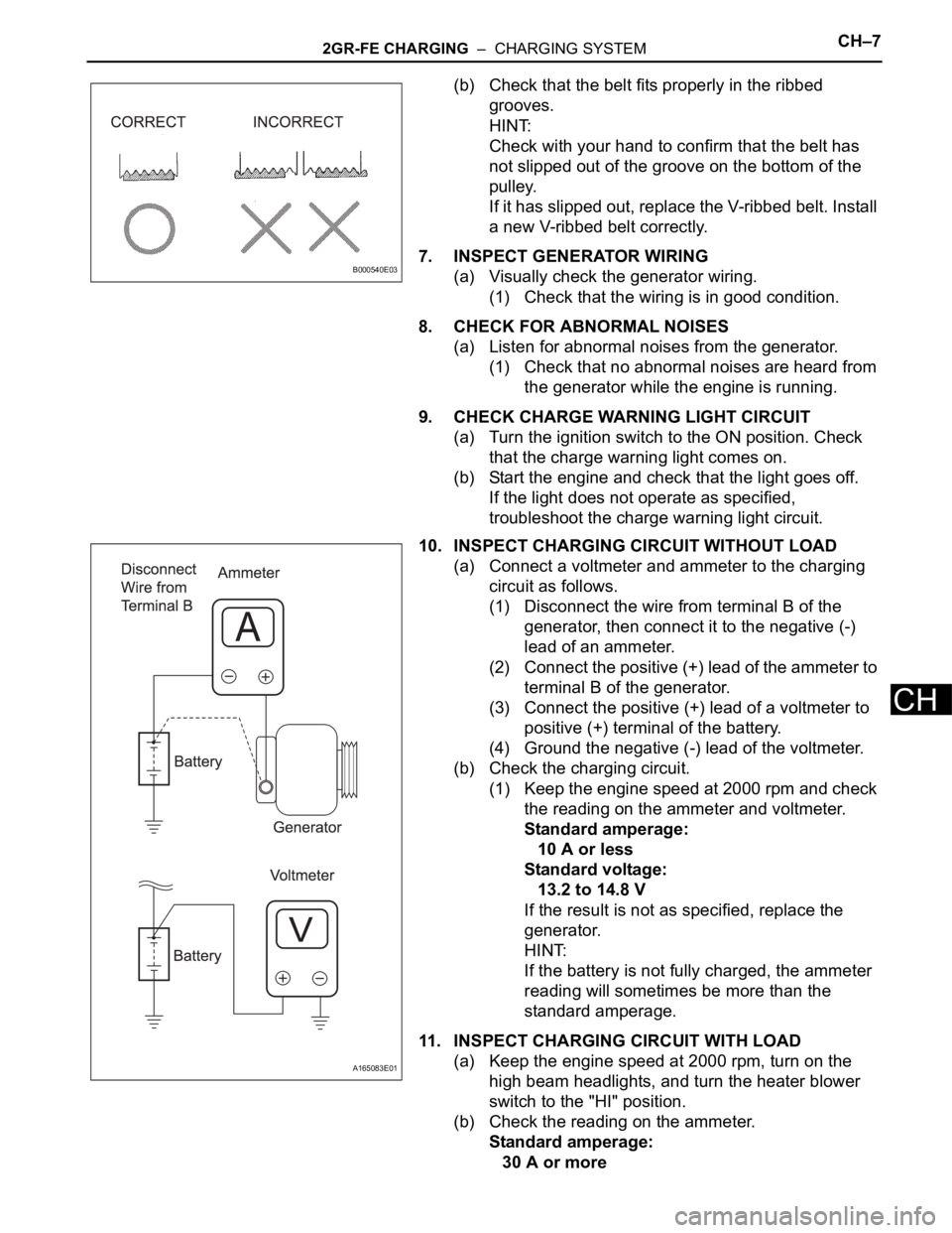
10. INSPECT CHARGING CIRCUIT WITHOUT LOAD
(a) Connect a voltmeter and ammeter to the charging
circuit as follows.
(1) Disconnect the wire from terminal B of the
generator, then connect it to the negative (-)
lead of an ammeter.
(2) Connect the positive (+) lead of the ammeter to
terminal B of the generator.
(3) Connect the positive (+) lead of a voltmeter to
positive (+) terminal of the battery.
(4) Ground the negative (-) lead of the voltmeter.
(b) Check the charging circuit.
(1) Keep the engine speed at 2000 rpm and check
the reading on the ammeter and voltmeter.
Standard amperage:
10 A or less
Standard voltage:
13.2 to 14.8 V
If the result is not as specified, replace the
generator.
HINT:
If the battery is not fully charged, the ammeter
reading will sometimes be more than the
standard amperage.
11. INSPECT CHARGING CIRCUIT WITH LOAD
(a) Keep the engine speed at 2000 rpm, turn on the
high beam headlights, and turn the heater blower
switch to the "HI" position.
(b) Check the reading on the ammeter.
Standard amperage:
30 A or more
B000540E03
A165083E01