2007 TOYOTA SIENNA wiring
[x] Cancel search: wiringPage 1723 of 3000

U151F AUTOMATIC TRANSAXLE – AUTOMATIC TRANSAXLE SYSTEMAX–51
AX
MONITOR DESCRIPTION
These DTCs indicate an open or short in the automatic transmission fluid (ATF) temperature sensor (TFT
sensor) circuit. The automatic transmission fluid (ATF) temperature sensor converts ATF temperature to
an electrical resistance value. Based on the resistance, the ECM determines the ATF temperature, and
the ECM detects an opens or shorts in the ATF temperature circuit. If the resistance value of the ATF
temperature is less than 79
*1or more than 156 k *2, the ECM interprets this as a fault in the ATF
sensor or wiring. The ECM will turn on the MIL and store the DTC.
*1: 150
C (302F) or more is indicated regardless of the actual ATF temperature.
*2: -40
C (-40F) is indicated regardless of the actual ATF temperature.
HINT:
The ATF temperature can be checked on the OBD II scan tool or intelligent tester display.
MONITOR STRATEGY
TYPICAL ENABLING CONDITIONS
P0710: Range check (Chattering)
P0712: Range check (Low resistance)
P0713: Range check (High resistance)
TYPICAL MALFUNCTION THRESHOLDS
P0710: Range check (Chattering)
P0712: Range check (Low resistance)
P0713: Range check (High resistance)
P0712ATF temperature sensor resistance is less than 79
for 0.5 sec. or more (1-trip detection logic)• Short in ATF temperature sensor circuit
• Transmission wire (ATF temperature sensor)
•ECM
P0713ATF temperature sensor resistance is more than 156
k
when 15 minutes or more have elapsed after the
engine start
DTC is detected for 0.5 sec. or more (1-trip detection
logic)• Open in ATF temperature sensor circuit
• Transmission wire (ATF temperature sensor)
•ECM
Related DTCsP0710: ATF temperature sensor/Range check (Chattering)
P0712: ATF temperature sensor/Range check (Low resistance)
P0713: ATF temperature sensor/Range check (High resistance)
Required sensors/Components ATF temperature sensor (TFT sensor)
Frequency of operation Continuous
Duration 0.5 sec.
MIL operation Immediate
Sequence of operation None
The monitor will run whenever these DTCs are not present. None
The typical enabling condition is not available. -
The monitor will run whenever this DTC is not present. None
Time after engine start 15 min. or more
TFT (Transmission fluid temperature) sensor resistanceLess than 79
or
More than 156 k
TFT sensor resistanceLess than 79
TFT sensor resistance More than 156 k
DTC No. DTC Detection Condition Trouble Area
Page 1724 of 3000
AX–52U151F AUTOMATIC TRANSAXLE – AUTOMATIC TRANSAXLE SYSTEM
AX
COMPONENT OPERATING RANGE
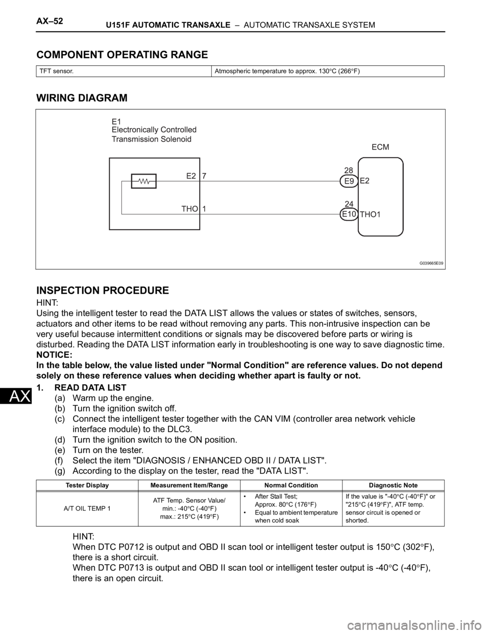
WIRING DIAGRAM
INSPECTION PROCEDURE
HINT:
Using the intelligent tester to read the DATA LIST allows the values or states of switches, sensors,
actuators and other items to be read without removing any parts. This non-intrusive inspection can be
very useful because intermittent conditions or signals may be discovered before parts or wiring is
disturbed. Reading the DATA LIST information early in troubleshooting is one way to save diagnostic time.
NOTICE:
In the table below, the value listed under "Normal Condition" are reference values. Do not depend
solely on these reference values when deciding whether apart is faulty or not.
1. READ DATA LIST
(a) Warm up the engine.
(b) Turn the ignition switch off.
(c) Connect the intelligent tester together with the CAN VIM (controller area network vehicle
interface module) to the DLC3.
(d) Turn the ignition switch to the ON position.
(e) Turn on the tester.
(f) Select the item "DIAGNOSIS / ENHANCED OBD II / DATA LIST".
(g) According to the display on the tester, read the "DATA LIST".
HINT:
When DTC P0712 is output and OBD II scan tool or intelligent tester output is 150
C (302F),
there is a short circuit.
When DTC P0713 is output and OBD II scan tool or intelligent tester output is -40
C (-40F),
there is an open circuit.
TFT sensor. Atmospheric temperature to approx. 130C (266F)
Tester Display Measurement Item/Range Normal Condition Diagnostic Note
A/T OIL TEMP 1AT F Te m p . S e n s o r Va l u e /
min.: -40
C (-40F)
max.: 215
C (419F)• After Stall Test;
Approx. 80
C (176F)
• Equal to ambient temperature
when cold soakIf the value is "-40
C (-40F)" or
"215
C (419F)", ATF temp.
sensor circuit is opened or
shorted.
G039665E09
Page 1728 of 3000
AX–56U151F AUTOMATIC TRANSAXLE – AUTOMATIC TRANSAXLE SYSTEM
AX
Condition (C):
Condition (D):
TYPICAL MALFUNCTION THRESHOLDS
Condition (A), (B), (C):
Condition (D):
COMPONENT OPERATING RANGE
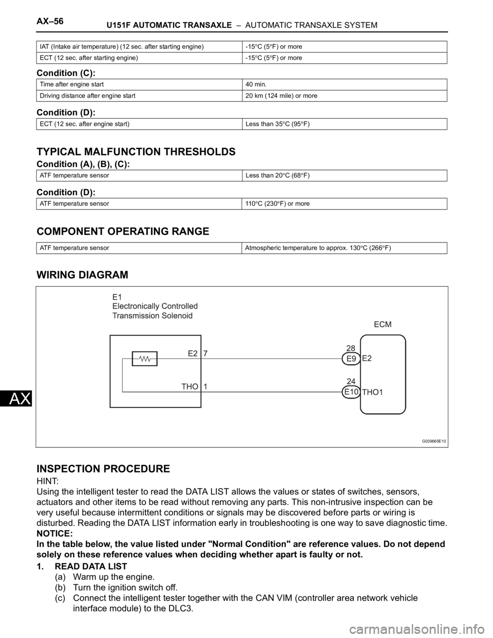
WIRING DIAGRAM
INSPECTION PROCEDURE
HINT:
Using the intelligent tester to read the DATA LIST allows the values or states of switches, sensors,
actuators and other items to be read without removing any parts. This non-intrusive inspection can be
very useful because intermittent conditions or signals may be discovered before parts or wiring is
disturbed. Reading the DATA LIST information early in troubleshooting is one way to save diagnostic time.
NOTICE:
In the table below, the value listed under "Normal Condition" are reference values. Do not depend
solely on these reference values when deciding whether apart is faulty or not.
1. READ DATA LIST
(a) Warm up the engine.
(b) Turn the ignition switch off.
(c) Connect the intelligent tester together with the CAN VIM (controller area network vehicle
interface module) to the DLC3.
IAT (Intake air temperature) (12 sec. after starting engine) -15C (5F) or more
ECT (12 sec. after starting engine) -15
C (5F) or more
Time after engine start 40 min.
Driving distance after engine start 20 km (124 mile) or more
ECT (12 sec. after engine start) Less than 35
C (95F)
ATF temperature sensor Less than 20
C (68F)
ATF temperature sensor 110
C (230F) or more
ATF temperature sensor Atmospheric temperature to approx. 130
C (266F)
G039665E10
Page 1732 of 3000
AX–60U151F AUTOMATIC TRANSAXLE – AUTOMATIC TRANSAXLE SYSTEM
AX
TYPICAL ENABLING CONDITIONS
TYPICAL MALFUNCTION THRESHOLDS
COMPONENT OPERATING RANGE
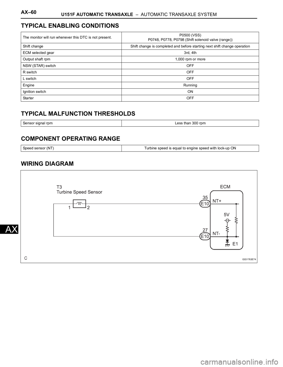
WIRING DIAGRAM
The monitor will run whenever this DTC is not present.P0500 (VSS)
P0748, P0778, P0798 (Shift solenoid valve (range))
Shift change Shift change is completed and before starting next shift change operation
ECM selected gear3rd, 4th
Output shaft rpm1,000 rpm or more
NSW (STAR) switchOFF
R switchOFF
L switchOFF
EngineRunning
Ignition switchON
StarterOFF
Sensor signal rpmLess than 300 rpm
Speed sensor (NT) Turbine speed is equal to engine speed with lock-up ON
G031763E74
Page 1736 of 3000

AX–64U151F AUTOMATIC TRANSAXLE – AUTOMATIC TRANSAXLE SYSTEM
AX
WIRING DIAGRAM
INSPECTION PROCEDURE
HINT:
Using the intelligent tester to read the DATA LIST allows the
values or states of switches, sensors, actuators and other
items to be read without removing any parts. This non-
intrusive inspection can be very useful because intermittent
conditions or signals may be discovered before parts or
wiring is disturbed. Reading the DATA LIST information early
in troubleshooting is one way to save diagnostic time.
(a) Warm up the engine.
(b) Turn the ignition switch off.
(c) Connect the OBD II scan tool or intelligent tester
together with the CAN VIM (controller area network
vehicle interface module) to the DLC3.
(d) Turn the ignition switch to the ON position.
(e) Turn on the tester.
(f) Select the item "DIAGNOSIS / ENHANCED OBD II /
DATA LIST".
1READ VALUE OF DATA LIST
C160582E01
Page 1741 of 3000
U151F AUTOMATIC TRANSAXLE – AUTOMATIC TRANSAXLE SYSTEMAX–69
AX
INSPECTION PROCEDURE
HINT:
Using the intelligent tester to perform ACTIVE TEST allows relays, VSVs, actuators and other items to be
operated without removing any parts. This non-intrusive functional inspection can be very useful because
intermittent operation may be discovered before parts or wiring is disturbed. Performing ACTIVE TEST
early in troubleshooting is one way to save diagnostic time. DATA LIST information can be displayed while
performing ACTIVE TEST.
1. PERFORM ACTIVE TEST
(a) Warm up the engine.
(b) Turn the ignition switch off.
(c) Connect the intelligent tester together with the CAN VIM (controller area network vehicle
interface module) to the DLC3.
(d) Turn the ignition switch to the ON position.
(e) Turn on the tester.
(f) Select the item "DIAGNOSIS / ENHANCED OBD II / ACTIVE TEST".
(g) According to the display on the tester, perform the "ACTIVE TEST".
HINT:
• This test can be conducted when the vehicle speed is 60 km/h (37 mph) or more.
• This test can be conducted in the 5th gear.
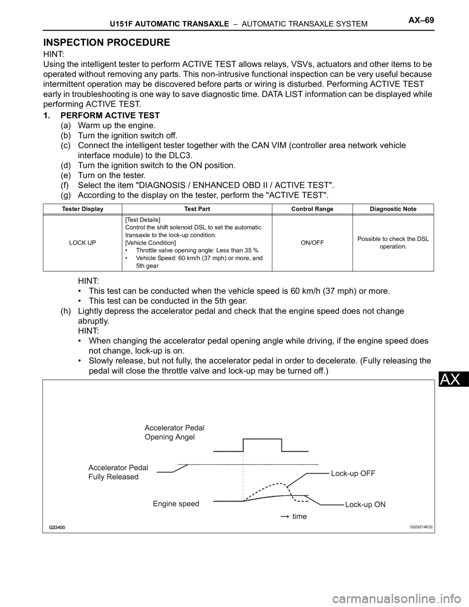
(h) Lightly depress the accelerator pedal and check that the engine speed does not change
abruptly.
HINT:
• When changing the accelerator pedal opening angle while driving, if the engine speed does
not change, lock-up is on.
• Slowly release, but not fully, the accelerator pedal in order to decelerate. (Fully releasing the
pedal will close the throttle valve and lock-up may be turned off.)
Tester Display Test Part Control Range Diagnostic Note
LOCK UP[Test Details]
Control the shift solenoid DSL to set the automatic
transaxle to the lock-up condition.
[Vehicle Condition]
• Throttle valve opening angle: Less than 35 %
• Vehicle Speed: 60 km/h (37 mph) or more, and
5th gearON/OFFPossible to check the DSL
operation.
G029214E02
Page 1746 of 3000

AX–74U151F AUTOMATIC TRANSAXLE – AUTOMATIC TRANSAXLE SYSTEM
AX
OFF malfunction:
ON malfunction:
TYPICAL MALFUNCTION THRESHOLDS
Either of the following conditions is met: OFF malfunction or ON malfunction
OFF malfunction:
2 detections are necessary per driving cycle:
1st detection; temporary flag ON
2nd detection; pending fault code ON
ON malfunction:
INSPECTION PROCEDURE
HINT:
Using the intelligent tester to perform ACTIVE TEST allows relays, VSVs, actuators and other items to be
operated without removing any parts. This non-intrusive functional inspection can be very useful because
intermittent operation may be discovered before parts or wiring is disturbed. Performing ACTIVE TEST
early in troubleshooting is one way to save diagnostic time. DATA LIST information can be displayed while
performing ACTIVE TEST.
1. PERFORM ACTIVE TEST
(a) Warm up the engine.
(b) Turn the ignition switch off.
(c) Connect the intelligent tester together with the CAN VIM (controller area network vehicle
interface module) to the DLC3.
(d) Turn the ignition switch to the ON position.
(e) Turn on the tester.
(f) Select the item "DIAGNOSIS / ENHANCED OBD II / ACTIVE TEST / SHIFT".
(g) According to the display on the tester, perform the "ACTIVE TEST".
HINT:
While driving, the shift position can be forcibly changed with the intelligent tester.
Shift solenoid valve SL3 circuit Not circuit malfunction
Shift solenoid valve S4 circuit Not circuit malfunction
Shift solenoid valve SR circuit Not circuit malfunction
Shift solenoid valve DSL circuit Not circuit malfunction
Electronic throttle systemNot circuit malfunction
ECM selected gear1st
Vehicle speedLess than 40 km/h (24.9 mph)
Throttle valve opening angle4.5% or more at engine speed 1,900 rpm
(Varies with engine speed)
ECM selected gear2nd
Throttle valve opening angle4.5% or more at engine speed 1,900 rpm
(Varies with engine speed)
Input (turbine) speed/Intermediate shaft speed 1.49 to 1.63
Input (turbine) speed/Intermediate shaft speed 2.72 to 2.86
Page 1750 of 3000
AX–78U151F AUTOMATIC TRANSAXLE – AUTOMATIC TRANSAXLE SYSTEM
AX
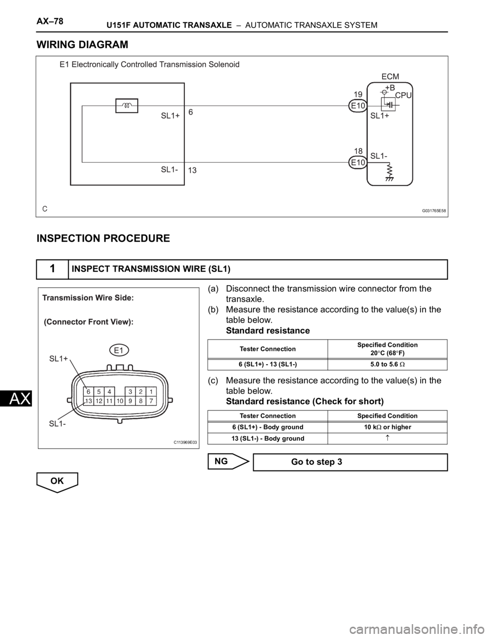
WIRING DIAGRAM
INSPECTION PROCEDURE
(a) Disconnect the transmission wire connector from the
transaxle.
(b) Measure the resistance according to the value(s) in the
table below.
Standard resistance
(c) Measure the resistance according to the value(s) in the
table below.
Standard resistance (Check for short)
NG
OK
1INSPECT TRANSMISSION WIRE (SL1)
G031765E58
C113969E03
Tester ConnectionSpecified Condition
20C (68F)
6 (SL1+) - 13 (SL1-) 5.0 to 5.6
Tester Connection Specified Condition
6 (SL1+) - Body ground 10 k
or higher
13 (SL1-) - Body ground
Go to step 3