Page 1787 of 3000
U151F AUTOMATIC TRANSAXLE – AUTOMATIC TRANSAXLE SYSTEMAX–115
AX
TYPICAL MALFUNCTION THRESHOLDS
P0985: Range check (Low resistance):
P0986: Range check (High resistance):
COMPONENT OPERATING RANGE
WIRING DIAGRAM
INSPECTION PROCEDURE
(a) Disconnect the transmission wire connector from the
transaxle.
(b) Measure the resistance according to the value(s) in the
table below.
Standard resistance
NG
OK
Shift solenoid valve SR resistance 8 or less
Shift solenoid valve SR resistance 100 k
or more
Shift solenoid valve SR Resistance: 11 to 15
at 20C (68F)
1INSPECT TRANSMISSION WIRE (SR)
G031165E83
C113969E08
Tester ConnectionSpecified Condition
20C (68F)
9 (SR) - Body ground 11 to 15
Go to step 3
Page 1796 of 3000
AX–124U151F AUTOMATIC TRANSAXLE – AUTOMATIC TRANSAXLE SYSTEM
AX
TYPICAL ENABLING CONDITIONS
TYPICAL MALFUNCTION THRESHOLDS
COMPONENT OPERATING RANGE
WIRING DIAGRAM
The monitor will run whenever this DTC is not present. None
Solenoid current cut status Not cut
Battery voltage11 V or more
Ignition switchON
StarterOFF
CPU commanded duty ratio to SLT 19% or more
Solenoid status from IC Fail (Open or short)
Shift solenoid valve SLT Resistance: 5.0 to 5.6
at 20C (68F)
G031770E39
Page 1800 of 3000
AX–128U151F AUTOMATIC TRANSAXLE – AUTOMATIC TRANSAXLE SYSTEM
AX
TYPICAL MALFUNCTION THRESHOLDS
P2769: Range check (Low resistance):
P2770: Range check (High resistance):
COMPONENT OPERATING RANGE
WIRING DIAGRAM
INSPECTION PROCEDURE
(a) Disconnect the transmission wire connector from the
transaxle.
(b) Measure the resistance according to the value(s) in the
table below.
Standard resistance
NG
StarterOFF
Shift solenoid valve DSL resistance 8
or less
Shift solenoid valve DSL resistance 100 k
or more
Shift solenoid valve DSL Resistance: 11 to 13
at 20C (68F)
1INSPECT TRANSMISSION WIRE (DSL)
G031165E84
C113969E11
Tester ConnectionSpecified Condition
20C (68F)
10 (DSL) - Body ground 11 to 13
Go to step 3
Page 1833 of 3000

U151F AUTOMATIC TRANSAXLE – AUTOMATIC TRANSAXLE SYSTEMAX–25
AX
TERMINALS OF ECM
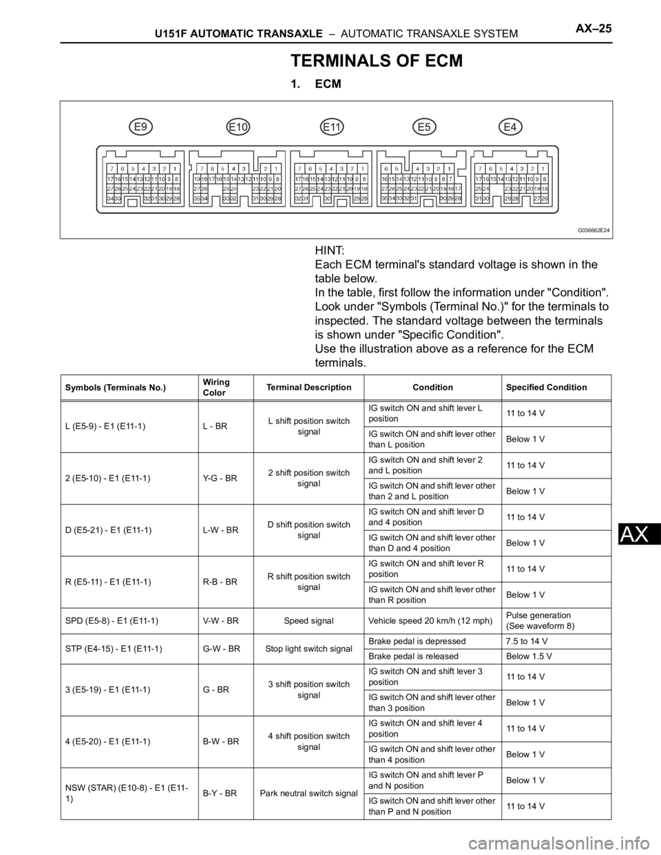
1. ECM
HINT:
Each ECM terminal's standard voltage is shown in the
table below.
In the table, first follow the information under "Condition".
Look under "Symbols (Terminal No.)" for the terminals to
inspected. The standard voltage between the terminals
is shown under "Specific Condition".
Use the illustration above as a reference for the ECM
terminals.
G036662E24
Symbols (Terminals No.)Wiring
ColorTerminal Description Condition Specified Condition
L (E5-9) - E1 (E11-1) L - BRL shift position switch
signalIG switch ON and shift lever L
position11 to 14 V
IG switch ON and shift lever other
than L positionBelow 1 V
2 (E5-10) - E1 (E11-1) Y-G - BR2 shift position switch
signalIG switch ON and shift lever 2
and L position11 to 14 V
IG switch ON and shift lever other
than 2 and L positionBelow 1 V
D (E5-21) - E1 (E11-1) L-W - BRD shift position switch
signalIG switch ON and shift lever D
and 4 position11 to 14 V
IG switch ON and shift lever other
than D and 4 positionBelow 1 V
R (E5-11) - E1 (E11-1) R-B - BRR shift position switch
signalIG switch ON and shift lever R
position11 to 14 V
IG switch ON and shift lever other
than R positionBelow 1 V
SPD (E5-8) - E1 (E11-1) V-W - BR Speed signal Vehicle speed 20 km/h (12 mph)Pulse generation
(See waveform 8)
STP (E4-15) - E1 (E11-1) G-W - BR Stop light switch signalBrake pedal is depressed 7.5 to 14 V
Brake pedal is released Below 1.5 V
3 (E5-19) - E1 (E11-1) G - BR3 shift position switch
signalIG switch ON and shift lever 3
position11 to 14 V
IG switch ON and shift lever other
than 3 positionBelow 1 V
4 (E5-20) - E1 (E11-1) B-W - BR4 shift position switch
signalIG switch ON and shift lever 4
position11 to 14 V
IG switch ON and shift lever other
than 4 positionBelow 1 V
NSW (STAR) (E10-8) - E1 (E11-
1)B-Y - BR Park neutral switch signalIG switch ON and shift lever P
and N positionBelow 1 V
IG switch ON and shift lever other
than P and N position11 to 14 V
Page 1834 of 3000

AX–26U151F AUTOMATIC TRANSAXLE – AUTOMATIC TRANSAXLE SYSTEM
AX
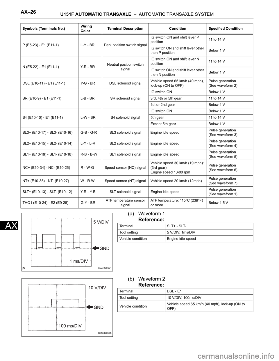
(a) Waveform 1
Reference:
(b) Waveform 2
Reference:
P (E5-23) - E1 (E11-1) L-Y - BR Park position switch signalIG switch ON and shift lever P
position11 to 14 V
IG switch ON and shift lever other
then P positionBelow 1 V
N (E5-22) - E1 (E11-1) Y-R - BRNeutral position switch
signalIG switch ON and shift lever N
position11 to 14 V
IG switch ON and shift lever other
then N positionBelow 1 V
DSL (E10-11) - E1 (E11-1) Y-G - BR DSL solenoid signalVehicle speed 65 km/h (40 mph),
lock-up (ON to OFF)Pulse generation
(See waveform 2)
SR (E10-9) - E1 (E11-1) L-B - BR SR solenoid signalIG switch ON Below 1 V
3rd, 4th or 5th gear 11 to 14 V
1st or 2nd gear Below 1 V
S4 (E10-10) - E1 (E11-1) L-W - BR S4 solenoid signalIG switch ON Below 1 V
5th gear 11 to 14 V
Except 5th gear Below 1 V
SL3+ (E10-17) - SL3- (E10-16) G-B - G-R SL3 solenoid signal Engine idle speedPulse generation
(See waveform 3)
SL2+ (E10-15) - SL2- (E10-14) L-Y - L-R SL2 solenoid signal Engine idle speedPulse generation
(See waveform 4)
SL1+ (E10-19) - SL1- (E10-18) R-B - B-W SL1 solenoid signal Engine idle speedPulse generation
(See waveform 5)
NC+ (E10-34) - NC- (E10-26) R - W-G Speed sensor (NC) signalVehicle speed 30 km/h (19 mph):
(3rd gear)
Engine speed 1,400 rpmPulse generation
(See waveform 6)
NT+ (E10-35) - NT- (E10-27) W - R-W Speed sensor (NT) signal Vehicle speed 20 km/h (12mph)Pulse generation
(See waveform 7)
SLT+ (E10-13) - SLT- (E10-12) Y-R - Y-B SLT solenoid signal Engine idle speedPulse generation
(See waveform 1)
THO1 (E10-24) - E2 (E9-28) G-Y - BRATF temperature sensor
signalATF temperature: 115
C (239F)
or moreBelow 1.5 V Symbols (Terminals No.)Wiring
ColorTerminal Description Condition Specified Condition
G023426E01
Terminal SLT+ - SLT-
Tool setting 5 V/DIV, 1ms/DIV
Vehicle condition Engine idle speed
C053420E05
Terminal DSL - E1
Tool setting 10 V/DIV, 100ms/DIV
Vehicle conditionVehicle speed 65 km/h (40 mph), lock-up (ON to
OFF)
Page 2279 of 3000

TW–32TIRE AND WHEEL – TIRE PRESSURE WARNING SYSTEM
TW
TERMINALS OF ECU
1. CHECK TIRE PRESSURE WARNING ECU
HINT:
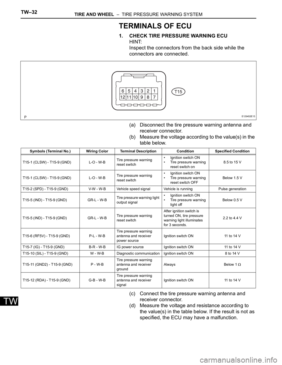
Inspect the connectors from the back side while the
connectors are connected.
(a) Disconnect the tire pressure warning antenna and
receiver connector.
(b) Measure the voltage according to the value(s) in the
table below.
(c) Connect the tire pressure warning antenna and
receiver connector.
(d) Measure the voltage and resistance according to
the value(s) in the table below. If the result is not as
specified, the ECU may have a malfunction.
E129452E15
Symbols (Terminal No.) Wiring Color Terminal Description ConditionSpecified Condition
T15-1 (CLSW) - T15-9 (GND) L-O - W-BTire pressure warning
reset switch• Ignition switch ON
• Tire pressure warning
reset switch on8.5 to 15 V
T15-1 (CLSW) - T15-9 (GND) L-O - W-BTire pressure warning
reset switch• Ignition switch ON
• Tire pressure warning
reset switch OFFBelow 1.5 V
T15-2 (SPD) - T15-9 (GND) V-W - W-B Vehicle speed signal Vehicle is running Pulse generation
T15-5 (IND) - T15-9 (GND) GR-L - W-BTire pressure warning light
output signal• Ignition switch ON
• Tire pressure warning
light offBelow 0.5 V
T15-5 (IND) - T15-9 (GND) GR-L - W-BTire pressure warning
reset switchAfter ignition switch is
turned ON, tire pressure
warning light illuminates
for 3 seconds.2.2 to 4.4 V
T15-6 (RF5V) - T15-9 (GND) P-L - W-BTire pressure warning
antenna and receiver
power sourceIgnition switch ON 11 to 14 V
T15-7 (IG) - T15-9 (GND) B-R - W-B IG power source Ignition switch ON 11 to 14 V
T15-10 (SIL) - T15-9 (GND) W - W-B Diagnostic communication Ignition switch ON 8 to 14 V
T15-11 (GND2) - T15-9 (GND) P - W-BTire pressure warning
antenna and receiver
groundAlways Below 1
T15-12 (RDA) - T15-9 (GND) G-B - W-BTire pressure warning
antenna and receiver
signalIgnition switch ON 11 to 14 V
Page 2282 of 3000

TW–38TIRE AND WHEEL – TIRE PRESSURE WARNING SYSTEM
TW
DATA LIST / ACTIVE TEST
1. DATA LIST
HINT:
Using the intelligent tester to read the DATA LIST allows
the values or states of switches, sensor, actuators and
other items to be read without removing any parts. This
non-intrusive inspection can be very useful because
intermittent conditions or signals may be discovered
before parts or wiring is disturbed. Reading the DATA
LIST information early in troubleshooting is one way to
save diagnostic time.
NOTICE:
In the table below, the values listed under "Normal
Condition" are reference values. Do not depend
solely on these reference values when deciding
whether a part is faulty or not.
(a) Make sure that the ignition switch is off.
(b) Connect the intelligent tester to DLC3.
(c) Turn the ignition switch to the ON position.
(d) Following the display on the intelligent tester, read
"DATA LIST".
Tester Display Measurement Item/Range Normal Condition Diagnostic Note
MODE STATUSTire pressure warning system mode/NORMAL
or REG 2nd or REG M or TESTNORMAL: Normal mode
TEST: Test mode-
MAIN TIRENumber of main tire ID to be registered/0, 1, 2,
3, 40 to 4 should be displayed -
VEHICLE SPDVehicle speed reading/min.: 0 km/h (0 mph),
max.: 255 km/h (158 mph)Actual vehicle speedSpeed indicated on the
combination meter
REGIT ID1 CODE
Registered ID1 code/min.: 0, max.: FFFFFFF
*1The ID No. registered in the
transmitter ID1 is displayed-
REGIT ID2 CODE
Registered ID2 code/min.: 0, max.: FFFFFFF
*1The ID No. registered in the
transmitter ID2 is displayed-
REGIT ID3 CODE
Registered ID3 code/min.: 0, max.: FFFFFFF
*1The ID No. registered in the
transmitter ID3 is displayed-
REGIT ID4 CODE
Registered ID4 code/min.: 0, max.: FFFFFFF
*1The ID No. registered in the
transmitter ID4 is displayed-
TRANS STATUS ID code transmission status/FINISH or NOW FINISH or NOW -
INITIAL SW Tire pressure warning reset switch/ON, OFFON: Switch on
OFF: Switch off-
TIREPRESS1ID1 tire inflation pressure (Absolute pressure) /
min.: 100 kPa (1 kgf/cm
2, 14 psi)
max.: 449.35 kPa (4.5 kgf/cm2, 63 psi)Actual tire inflation pressureIf 100 kPa (1 kgf/cm
2, 14 psi)
for absolute pressure is
displayed, the data has not
been received.
*2
TIREPRESS2ID2 tire inflation pressure (Absolute pressure) /
min.: 100 kPa (1 kgf/cm2, 14 psi)
max.: 449.35 kPa (4.5 kgf/cm2, 63 psi)Actual tire inflation pressureIf 100 kPa (1 kgf/cm
2, 14 psi)
for absolute pressure is
displayed, the data has not
been received.
*2
TIREPRESS3ID3 tire inflation pressure (Absolute pressure) /
min.: 100 kPa (1 kgf/cm2, 14 psi)
max.: 449.35 kPa (4.5 kgf/cm2, 63 psi)Actual tire inflation pressureIf 100 kPa (1 kgf/cm
2, 14 psi)
for absolute pressure is
displayed, the data has not
been received.
*2
TIREPRESS4ID4 tire inflation pressure (Absolute pressure) /
min.: 100 kPa (1 kgf/cm2, 14 psi)
max.: 449.35 kPa (4.5 kgf/cm2, 63 psi)Actual tire inflation pressureIf 100 kPa (1 kgf/cm
2, 14 psi)
for absolute pressure is
displayed, the data has not
been received.
*2
Page 2288 of 3000
TW–46TIRE AND WHEEL – TIRE PRESSURE WARNING SYSTEM
TW
WIRING DIAGRAM
INSPECTION PROCEDURE
NOTICE:
• When replacing the tire pressure warning ECU, read the IDs stored in the ECU using the
intelligent tester and write them down before removal.
• It is necessary to perform initialization (See page TW-23) after registration (See page TW-20) of
the transmitter IDs into the tire pressure warning ECU after the ECU and/or valve and
transmitter have been replaced.
(a) Check if the vehicle is not located in areas such as
described below:
1CHECK FREQUENCY RECEIVING CONDITION
B166325E02