Page 1474 of 3000
AX–108U151E AUTOMATIC TRANSAXLE – AUTOMATIC TRANSAXLE SYSTEM
AX
WIRING DIAGRAM
INSPECTION PROCEDURE
(a) Disconnect the transmission wire connector from the
transaxle.
(b) Measure the resistance according to the value(s) in the
table below.
Standard resistance
(c) Measure the resistance according to the value(s) in the
table below.
Standard resistance (Check for short)
NG
OK
1INSPECT TRANSMISSION WIRE (SL3)
G031765E60
C113969E05
Tester ConnectionSpecified Condition
20C (68F)
4 (SL3+) - 11 (SL3-) 5.0 to 5.6
Tester Connection Specified Condition
4 (SL3+) - Body ground 10 k
or higher
11 (SL3-) - Body ground
Go to step 3
Page 1478 of 3000
AX–112U151E AUTOMATIC TRANSAXLE – AUTOMATIC TRANSAXLE SYSTEM
AX
TYPICAL MALFUNCTION THRESHOLDS
P0982: Range check (Low resistance):
P0983: Range check (High resistance):
COMPONENT OPERATING RANGE
WIRING DIAGRAM
INSPECTION PROCEDURE
(a) Disconnect the transmission wire connector from the
transaxle.
(b) Measure the resistance according to the value(s) in the
table below.
Standard resistance
NG
OK
Shift solenoid valve S4 resistance 8 or less
Shift solenoid valve S4 resistance 100 k
or more
Shift solenoid valve S4 Resistance: 11 to 15
at 20C (68F)
1INSPECT TRANSMISSION WIRE (S4)
G031165E82
C113969E07
Tester ConnectionSpecified Condition
20C (68F)
3 (S4) - Body ground 11 to 15
Go to step 3
Page 1481 of 3000
U151E AUTOMATIC TRANSAXLE – AUTOMATIC TRANSAXLE SYSTEMAX–115
AX
TYPICAL MALFUNCTION THRESHOLDS
P0985: Range check (Low resistance):
P0986: Range check (High resistance):
COMPONENT OPERATING RANGE
WIRING DIAGRAM
INSPECTION PROCEDURE
(a) Disconnect the transmission wire connector from the
transaxle.
(b) Measure the resistance according to the value(s) in the
table below.
Standard resistance
NG
OK
Shift solenoid valve SR resistance 8 or less
Shift solenoid valve SR resistance 100 k
or more
Shift solenoid valve SR Resistance: 11 to 15
at 20C (68F)
1INSPECT TRANSMISSION WIRE (SR)
G031165E83
C113969E08
Tester ConnectionSpecified Condition
20C (68F)
9 (SR) - Body ground 11 to 15
Go to step 3
Page 1490 of 3000
AX–124U151E AUTOMATIC TRANSAXLE – AUTOMATIC TRANSAXLE SYSTEM
AX
TYPICAL ENABLING CONDITIONS
TYPICAL MALFUNCTION THRESHOLDS
COMPONENT OPERATING RANGE
WIRING DIAGRAM
The monitor will run whenever this DTC is not present. None
Solenoid current cut status Not cut
Battery voltage11 V or more
Ignition switchON
StarterOFF
CPU commanded duty ratio to SLT 19% or more
Solenoid status from IC Fail (Open or short)
Shift solenoid valve SLT Resistance: 5.0 to 5.6
at 20C (68F)
G031770E39
Page 1494 of 3000
AX–128U151E AUTOMATIC TRANSAXLE – AUTOMATIC TRANSAXLE SYSTEM
AX
TYPICAL MALFUNCTION THRESHOLDS
P2769: Range check (Low resistance):
P2770: Range check (High resistance):
COMPONENT OPERATING RANGE
WIRING DIAGRAM
INSPECTION PROCEDURE
(a) Disconnect the transmission wire connector from the
transaxle.
(b) Measure the resistance according to the value(s) in the
table below.
Standard resistance
NG
StarterOFF
Shift solenoid valve DSL resistance 8
or less
Shift solenoid valve DSL resistance 100 k
or more
Shift solenoid valve DSL Resistance: 11 to 13
at 20C (68F)
1INSPECT TRANSMISSION WIRE (DSL)
G031165E84
C113969E11
Tester ConnectionSpecified Condition
20C (68F)
10 (DSL) - Body ground 11 to 13
Go to step 3
Page 1530 of 3000

U151E AUTOMATIC TRANSAXLE – AUTOMATIC TRANSAXLE SYSTEMAX–25
AX
TERMINALS OF ECM
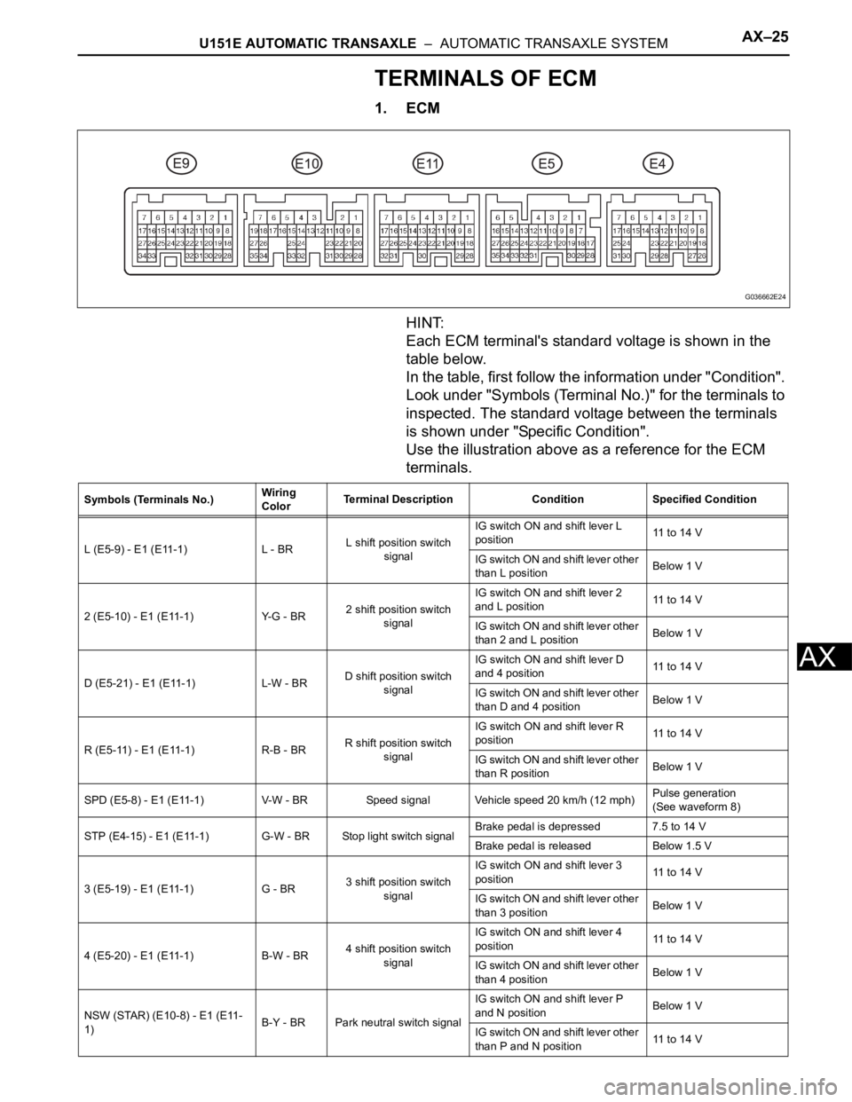
1. ECM
HINT:
Each ECM terminal's standard voltage is shown in the
table below.
In the table, first follow the information under "Condition".
Look under "Symbols (Terminal No.)" for the terminals to
inspected. The standard voltage between the terminals
is shown under "Specific Condition".
Use the illustration above as a reference for the ECM
terminals.
G036662E24
Symbols (Terminals No.)Wiring
ColorTerminal Description Condition Specified Condition
L (E5-9) - E1 (E11-1) L - BRL shift position switch
signalIG switch ON and shift lever L
position11 to 14 V
IG switch ON and shift lever other
than L positionBelow 1 V
2 (E5-10) - E1 (E11-1) Y-G - BR2 shift position switch
signalIG switch ON and shift lever 2
and L position11 to 14 V
IG switch ON and shift lever other
than 2 and L positionBelow 1 V
D (E5-21) - E1 (E11-1) L-W - BRD shift position switch
signalIG switch ON and shift lever D
and 4 position11 to 14 V
IG switch ON and shift lever other
than D and 4 positionBelow 1 V
R (E5-11) - E1 (E11-1) R-B - BRR shift position switch
signalIG switch ON and shift lever R
position11 to 14 V
IG switch ON and shift lever other
than R positionBelow 1 V
SPD (E5-8) - E1 (E11-1) V-W - BR Speed signal Vehicle speed 20 km/h (12 mph)Pulse generation
(See waveform 8)
STP (E4-15) - E1 (E11-1) G-W - BR Stop light switch signalBrake pedal is depressed 7.5 to 14 V
Brake pedal is released Below 1.5 V
3 (E5-19) - E1 (E11-1) G - BR3 shift position switch
signalIG switch ON and shift lever 3
position11 to 14 V
IG switch ON and shift lever other
than 3 positionBelow 1 V
4 (E5-20) - E1 (E11-1) B-W - BR4 shift position switch
signalIG switch ON and shift lever 4
position11 to 14 V
IG switch ON and shift lever other
than 4 positionBelow 1 V
NSW (STAR) (E10-8) - E1 (E11-
1)B-Y - BR Park neutral switch signalIG switch ON and shift lever P
and N positionBelow 1 V
IG switch ON and shift lever other
than P and N position11 to 14 V
Page 1531 of 3000

AX–26U151E AUTOMATIC TRANSAXLE – AUTOMATIC TRANSAXLE SYSTEM
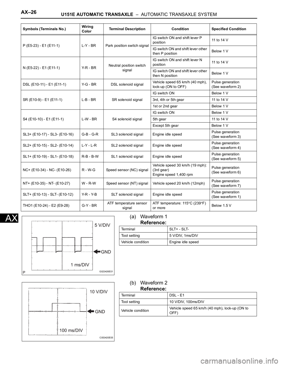
AX(a) Waveform 1
Reference:
(b) Waveform 2
Reference:
P (E5-23) - E1 (E11-1) L-Y - BR Park position switch signalIG switch ON and shift lever P
position11 to 14 V
IG switch ON and shift lever other
then P positionBelow 1 V
N (E5-22) - E1 (E11-1) Y-R - BRNeutral position switch
signalIG switch ON and shift lever N
position11 to 14 V
IG switch ON and shift lever other
then N positionBelow 1 V
DSL (E10-11) - E1 (E11-1) Y-G - BR DSL solenoid signalVehicle speed 65 km/h (40 mph),
lock-up (ON to OFF)Pulse generation
(See waveform 2)
SR (E10-9) - E1 (E11-1) L-B - BR SR solenoid signalIG switch ON Below 1 V
3rd, 4th or 5th gear 11 to 14 V
1st or 2nd gear Below 1 V
S4 (E10-10) - E1 (E11-1) L-W - BR S4 solenoid signalIG switch ON Below 1 V
5th gear 11 to 14 V
Except 5th gear Below 1 V
SL3+ (E10-17) - SL3- (E10-16) G-B - G-R SL3 solenoid signal Engine idle speedPulse generation
(See waveform 3)
SL2+ (E10-15) - SL2- (E10-14) L-Y - L-R SL2 solenoid signal Engine idle speedPulse generation
(See waveform 4)
SL1+ (E10-19) - SL1- (E10-18) R-B - B-W SL1 solenoid signal Engine idle speedPulse generation
(See waveform 5)
NC+ (E10-34) - NC- (E10-26) R - W-G Speed sensor (NC) signalVehicle speed 30 km/h (19 mph):
(3rd gear)
Engine speed 1,400 rpmPulse generation
(See waveform 6)
NT+ (E10-35) - NT- (E10-27) W - R-W Speed sensor (NT) signal Vehicle speed 20 km/h (12mph)Pulse generation
(See waveform 7)
SLT+ (E10-13) - SLT- (E10-12) Y-R - Y-B SLT solenoid signal Engine idle speedPulse generation
(See waveform 1)
THO1 (E10-24) - E2 (E9-28) G-Y - BRATF temperature sensor
signalATF temperature: 115
C (239F)
or moreBelow 1.5 V Symbols (Terminals No.)Wiring
ColorTerminal Description Condition Specified Condition
G023426E01
Terminal SLT+ - SLT-
Tool setting 5 V/DIV, 1ms/DIV
Vehicle condition Engine idle speed
C053420E05
Terminal DSL - E1
Tool setting 10 V/DIV, 100ms/DIV
Vehicle conditionVehicle speed 65 km/h (40 mph), lock-up (ON to
OFF)
Page 1719 of 3000
U151F AUTOMATIC TRANSAXLE – AUTOMATIC TRANSAXLE SYSTEMAX–47
AX
WIRING DIAGRAM
C160583E01