2007 TOYOTA SIENNA wiring
[x] Cancel search: wiringPage 815 of 3000

2GR-FE ENGINE CONTROL SYSTEM – SFI SYSTEMES–35
ES
STAR (NSW) (E10-8) - E1
(E11-1)B-Y - BRPark/Neutral position
switch signalIgnition switch ON, Shift lever
position P or N9 to 14 V
STAR (NSW) (E10-8) - E1
(E11-1)B-Y - BRPark/Neutral position
switch signalIgnition switch ON, Shift lever
position other than P or N9 to 14 V
STA (E11-11) - E1 (E11-1) B-L - BRStarter relay operation
signalCranking 9 to 14 V
OC2- (E11-14) - OC2+ (E11-
15)G-B - L-RCamshaft timing Oil
Control Valve (OCV)
operation signal (Intake
side)Ignition switch ONPulse generation
(see waveform 1)
OE2+ (E11-27) - OE2- (E11-
32)W - G-RCamshaft timing Oil
Control Valve (OCV)
operation signal (Intake
side)Ignition switch ONPulse generation
(see waveform 1)
OC1- (E11-16) - OC1+ (E11-
17)G-R - G-WCamshaft timing Oil
Control Valve (OCV)
operation signal (Intake
side)Ignition switch ONPulse generation
(see waveform 1)
OE1+ (E11-26) - OE1- (E11-
31)G - RCamshaft timing Oil
Control Valve (OCV)
operation signal (Intake
side)Ignition switch ONPulse generation
(see waveform 1)
VV2+ (E11-18) - VV2- (E11-
28)V - GVariable Valve Timing
(VVT) sensor signal
(Intake side)IdlingPulse generation
(see waveform 5)
VV1+ (E11-19) - VV1- (E11-
29)B-W - L-YVariable Valve Timing
(VVT) sensor signal
(Intake side)IdlingPulse generation
(see waveform 5)
NE- (E11-20) - NE+ (E11-21) B - WCrankshaft position sensor
signalIdlingPulse generation
(see waveform 5)
NE+ (E11-21) - NE- (E11-20) W - BCrankshaft position sensor
signalIdlingPulse generation
(see waveform 5)
EV2- (E11-22) - EV2+ (E11-
23)R - PVariable Valve Timing
(VVT) sensor signal
(Exhaust side)IdlingPulse generation
(see waveform 5)
EV2+ (E11-23) - EV2- (E11-
22)P - RVariable Valve Timing
(VVT) sensor signal
(Exhaust side)IdlingPulse generation
(see waveform 5)
EV1- (E11-24) - EV1+ (E11-
25)L-W - B-WVariable Valve Timing
(VVT) sensor signal
(Exhaust side)IdlingPulse generation
(see waveform 5)
EV1+ (E11-25) - EV1- (E11-
24)B-W - L-WVariable Valve Timing
(VVT) sensor signal
(Exhaust side)IdlingPulse generation
(see waveform 5)
VV2- (E11-28) - VV2+ (E11-
18)G - VVariable Valve Timing
(VVT) sensor signal
(Intake side)IdlingPulse generation
(see waveform 5)
VV1- (E11-29) - VV1+ (E11-
19)L-Y - B-WVariable Valve Timing
(VVT) sensor signal
(Intake side)IdlingPulse generation
(see waveform 5)
HT1B (E9-1) - E1 (E11-1)
HT2B (E10-5) - E1 (E11-1)L - BR
W-L - BRHeated oxygen sensor
heater operation signalIdling Below 3.0 V
HT1B (E9-1) - E1 (E11-1)
HT2B (E10-5) - E1 (E11-1)L - BR
W-L - BRHeated oxygen sensor
heater operation signalIgnition switch ON 9 to 14 V
ACM (E9-3) - E1 (E11-1) Y-G - BRVSV for active control
mount system operation
signalIgnition switch ON 9 to 14 V
M- (E9-4) - ME01 (E10-3) W - W-BThrottle drive motor
operation signal (negative
terminal)Idling with warm enginePulse generation
(see waveform 10) Symbols (Terminal No.) Wiring Colors Terminal Descriptions ConditionsSpecified
Condition
Page 816 of 3000

ES–362GR-FE ENGINE CONTROL SYSTEM – SFI SYSTEM
ES
M+ (E9-5) - ME01 (E10-3) B - W-BThrottle drive motor
operation signal (positive
terminal)Idling with warm enginePluse generation
(see waveform 9)
E02 (E9-6) - Body ground W-B - -Earth (ground) circuit of
ECMAlways Below 1 V
E01 (E9-7) - Body ground W-B - -Earth (ground) circuit of
ECMAlways Below 1 V
IGT1 (E9-8) - E1 (E11-1)
IGT2 (E9-9) - E1 (E11-1)
IGT3 (E9-10) - E1 (E11-1)
IGT4 (E9-11) - E1 (E11-1)
IGT5 (E9-12) - E1 (E11-1)
IGT6 (E9-13) - E1 (E11-1)R-L - BR
P - BR
Y- B - B R
L-Y - BR
G-Y - BR
L-R - BRIgnition coil with igniter
(ignition signal)IdlingPulse generation
(see waveform 6)
GE01 (E9-17) - E1 (E11-1) - - BRShielded earth (ground)
circuit of throttle drive
motorAlways Below 1 V
OX1B (E9-18) - E2 (E9-28)
OX2B (E10-33) - E2 (E9-28)W - BR
B - BRHeated oxygen sensor
signalWith engine speed at 2500 rpm
for 2 minutes after warming upPulse generation
(see waveform 2)
VTA2 (E9-19) - E2 (E9-28) B-R - BRThrottle position sensor
signal (for sensor
malfunction detection)Ignition switch ON, Accelerator
pedal fully released2.1 to 3.1 V
VTA2 (E9-19) - E2 (E9-28) B-R - BRThrottle position sensor
signal (for sensor
malfunction detection)Ignition switch ON, Accelerator
pedal fully depressed4.5 to 5.0 V
VTA1 (E9-20) - E2 (E9-28) LG - BRThrottle position sensor
signal (for engine control)Ignition switch ON, Throttle valve
fully closed0.5 to 1.2 V
VTA1 (E9-20) - E2 (E9-28) LG - BRThrottle position sensor
signal (for engine control)Ignition switch ON, Throttle valve
fully open3.2 to 4.8 V
THW (E9-21) - E2 (E9-28) G-B - BREngine coolant
temperature sensor signalIdling, Engine coolant
temperature 80
C (176F)0.2 to 1.0 V
THA (E9-22) - E2 (E9-28) L-B - BRIntake air temperature
sensor signalIdling, Intake air temperature
20
C (68F)0.5 to 3.4 V
VC (E9-23) - E2 (E9-28) Y - BRPower source of sensors
(specific voltage)Ignition switch ON 4.5 to 5.0 V
IGF1 (E9-24) - E1 (E11-1) W-R - BRIgnition coil with igniter
(ignition confirmation
signal)Ignition switch ON 4.5 to 5.0 V
IGF1 (E9-24) - E1 (E11-1) W-R - BRIgnition coil with igniter
(ignition confirmation
signal)IdlingPulse generation
(see waveform 6)
AICV (E9-27) - E1 (E11-1) W - BRVSV for Air intake control
system operation signalIgnition switch ON 9 to 14 V
E2 (E9-28) - E1 (E11-1) BR - BREarth (ground) circuit of
sensors for ETCSAlways Below 1 V
E2G (E9-29) - E1 (E11-1) L-W - BREarth (ground) circuit of
sensor for mass air flow
meterAlways Below 1 V
VG (E9-30) - E2G (E9-29) R - L-WMass Air Flow (MAF)
meter signalIdling, Shift lever position P or N,
A/C switch OFF0.5 to 3.0 V
ACIS (E9-33) - E1 (E11-1) R-Y - BRVSV for ACIS (Acoustic
Control Induction System)
operation signalIgnition switch ON 9 to 14 V
PRG (E9-34) - E1 (E11-1) G - BRPurge VSV for EVAP
system operation signalIgnition switch ON 9 to 14 V
PRG (E9-34) - E1 (E11-1) G - BRPurge VSV for EVAP
system operation signalIdlingPulse generation
(see waveform 7)
HA2A (E10-1) - E05 (E10-6) Y - W-BA/F sensor heater
operation signalIdling Below 3.0 V Symbols (Terminal No.) Wiring Colors Terminal Descriptions ConditionsSpecified
Condition
Page 817 of 3000

2GR-FE ENGINE CONTROL SYSTEM – SFI SYSTEMES–37
ES
*1: The ECM terminal voltage is constant regardless of
the output voltage from the sensor.
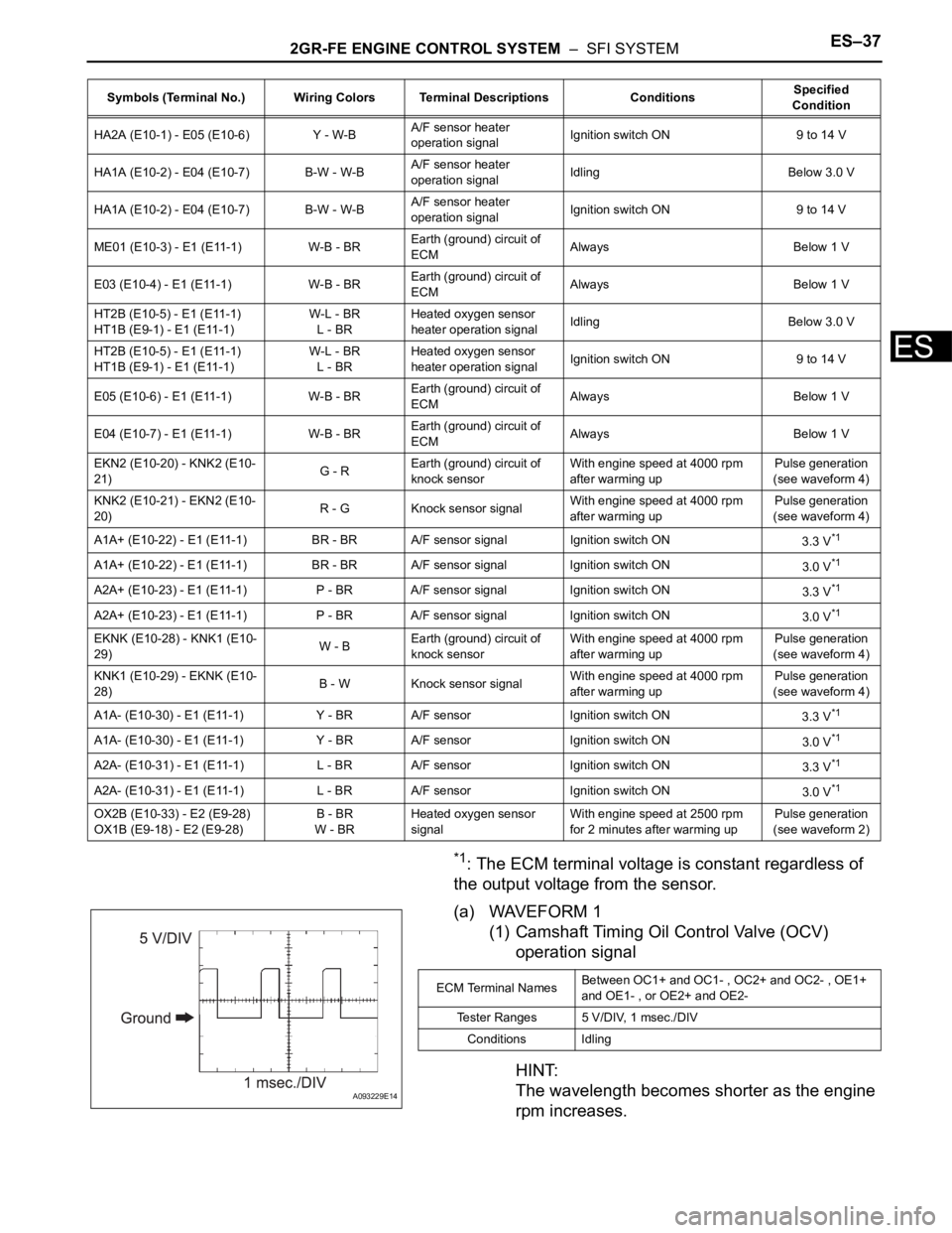
(a) WAVEFORM 1
(1) Camshaft Timing Oil Control Valve (OCV)
operation signal
HINT:
The wavelength becomes shorter as the engine
rpm increases.
HA2A (E10-1) - E05 (E10-6) Y - W-BA/F sensor heater
operation signalIgnition switch ON 9 to 14 V
HA1A (E10-2) - E04 (E10-7) B-W - W-BA/F sensor heater
operation signalIdling Below 3.0 V
HA1A (E10-2) - E04 (E10-7) B-W - W-BA/F sensor heater
operation signalIgnition switch ON 9 to 14 V
ME01 (E10-3) - E1 (E11-1) W-B - BREarth (ground) circuit of
ECMAlways Below 1 V
E03 (E10-4) - E1 (E11-1) W-B - BREarth (ground) circuit of
ECMAlways Below 1 V
HT2B (E10-5) - E1 (E11-1)
HT1B (E9-1) - E1 (E11-1)W-L - BR
L - BRHeated oxygen sensor
heater operation signalIdling Below 3.0 V
HT2B (E10-5) - E1 (E11-1)
HT1B (E9-1) - E1 (E11-1)W-L - BR
L - BRHeated oxygen sensor
heater operation signalIgnition switch ON 9 to 14 V
E05 (E10-6) - E1 (E11-1) W-B - BREarth (ground) circuit of
ECMAlways Below 1 V
E04 (E10-7) - E1 (E11-1) W-B - BREarth (ground) circuit of
ECMAlways Below 1 V
EKN2 (E10-20) - KNK2 (E10-
21)G - REarth (ground) circuit of
knock sensorWith engine speed at 4000 rpm
after warming upPulse generation
(see waveform 4)
KNK2 (E10-21) - EKN2 (E10-
20)R - G Knock sensor signalWith engine speed at 4000 rpm
after warming upPulse generation
(see waveform 4)
A1A+ (E10-22) - E1 (E11-1) BR - BR A/F sensor signal Ignition switch ON
3.3 V
*1
A1A+ (E10-22) - E1 (E11-1) BR - BR A/F sensor signal Ignition switch ON
3.0 V*1
A2A+ (E10-23) - E1 (E11-1) P - BR A/F sensor signal Ignition switch ON
3.3 V*1
A2A+ (E10-23) - E1 (E11-1) P - BR A/F sensor signal Ignition switch ON
3.0 V*1
EKNK (E10-28) - KNK1 (E10-
29)W - BEarth (ground) circuit of
knock sensorWith engine speed at 4000 rpm
after warming upPulse generation
(see waveform 4)
KNK1 (E10-29) - EKNK (E10-
28)B - W Knock sensor signalWith engine speed at 4000 rpm
after warming upPulse generation
(see waveform 4)
A1A- (E10-30) - E1 (E11-1) Y - BR A/F sensor Ignition switch ON
3.3 V
*1
A1A- (E10-30) - E1 (E11-1) Y - BR A/F sensor Ignition switch ON
3.0 V*1
A2A- (E10-31) - E1 (E11-1) L - BR A/F sensor Ignition switch ON
3.3 V*1
A2A- (E10-31) - E1 (E11-1) L - BR A/F sensor Ignition switch ON
3.0 V*1
OX2B (E10-33) - E2 (E9-28)
OX1B (E9-18) - E2 (E9-28)B - BR
W - BRHeated oxygen sensor
signalWith engine speed at 2500 rpm
for 2 minutes after warming upPulse generation
(see waveform 2) Symbols (Terminal No.) Wiring Colors Terminal Descriptions ConditionsSpecified
Condition
A093229E14
ECM Terminal NamesBetween OC1+ and OC1- , OC2+ and OC2- , OE1+
and OE1- , or OE2+ and OE2-
Tester Ranges 5 V/DIV, 1 msec./DIV
Conditions Idling
Page 848 of 3000

MULTIPLEX COMMUNICATION – MULTIPLEX COMMUNICATION SYSTEMMP–5
MP
TERMINALS OF ECU
1. MULTIPLEX NETWORK GATEWAY ECU
(a) Disconnect the G4 ECU connector.
(b) Measure the voltage between the specified
terminals on the wire harness side connector.
If the result is not as specified, there may be a
malfunction on the wire harness side.
(c) Measure the resistance between the specified
terminals on the wire harness side connector.
If the result is not as specified, there may be a
malfunction on the wire harness side.
C129903E02
Terminal No.
(Symbols)Wiring Color Terminal Description Condition Specified Condition
G4-1 (IG) - Body ground B-R - Body ground Power supply (IG) Ignition switch: ON 11 to 14 V
G4-2 (ACC) - Body ground P - Body ground Power source (ACC) Ignition switch: ACC 11 to 14 V
G4-10 (BATT) - Body
groundW-L - Body ground Power supply (Battery) Always 11 to 14 V
Terminal No.
(Symbols)Wiring Color Terminal Description Condition Specified Condition
G4-3 (MPD1) - Body
groundR-G - Body ground MPX line Always 10 k
or higher
G4-12 (MPD2) - Body
groundR-L - Body ground MPX line Always 10 k
or higher
G4-24 (GND) - Body
groundW-B - Body ground Ground Always Below 1
Page 850 of 3000

MULTIPLEX COMMUNICATION – MULTIPLEX COMMUNICATION SYSTEMMP–7
MP
(b) Measure the voltage between the specified
terminals on the wire harness side connector.
If the result is not as specified, there may be a
malfunction on the wire harness side.
(c) Measure the resistance between the specified
terminals on the wire harness side connector.
If the result is not as specified, there may be a
malfunction on the wire harness side.
3. AIRBAG SENSOR ASSEMBLY
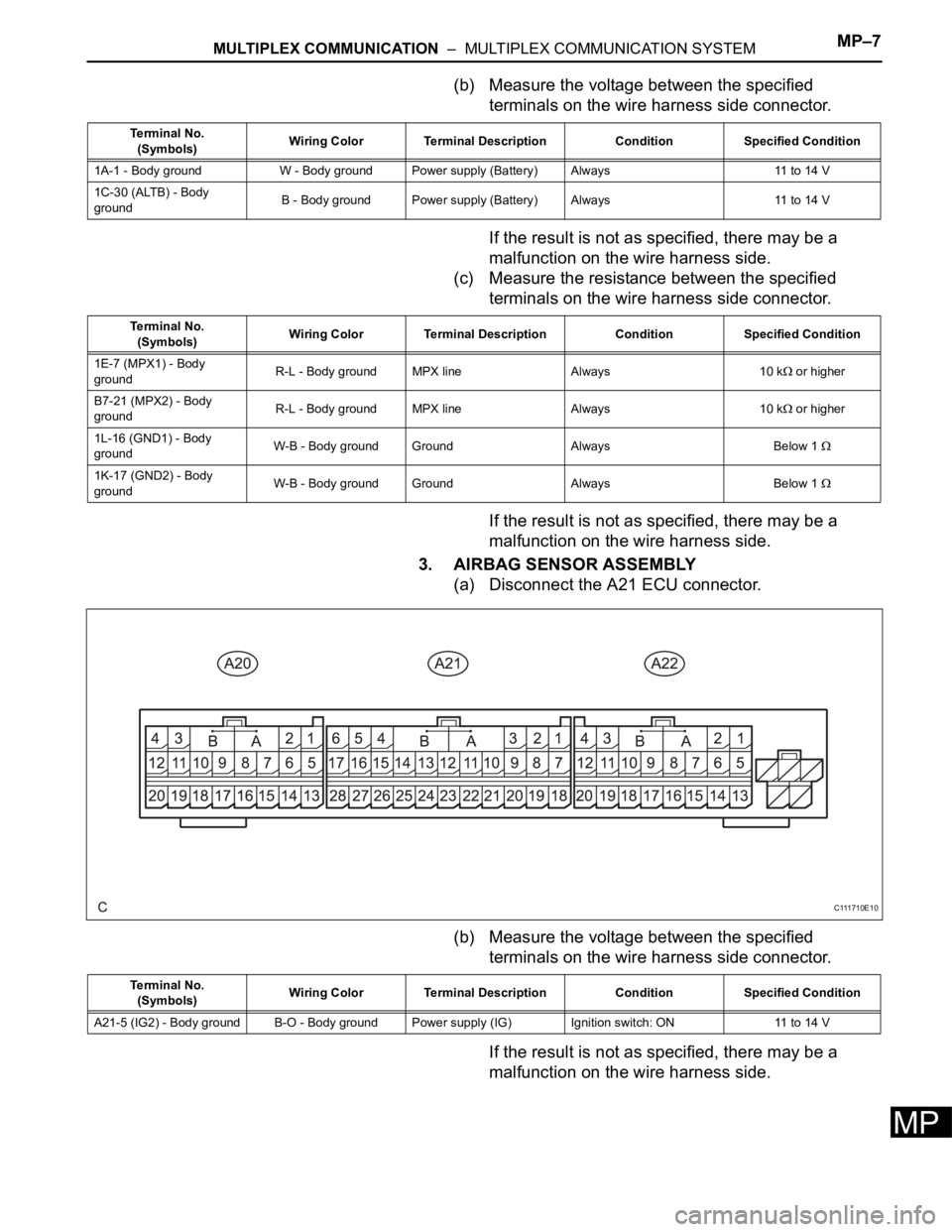
(a) Disconnect the A21 ECU connector.
(b) Measure the voltage between the specified
terminals on the wire harness side connector.
If the result is not as specified, there may be a
malfunction on the wire harness side.
Terminal No.
(Symbols)Wiring Color Terminal Description Condition Specified Condition
1A-1 - Body ground W - Body ground Power supply (Battery) Always 11 to 14 V
1C-30 (ALTB) - Body
groundB - Body ground Power supply (Battery) Always 11 to 14 V
Terminal No.
(Symbols)Wiring Color Terminal Description Condition Specified Condition
1E-7 (MPX1) - Body
groundR-L - Body ground MPX line Always 10 k
or higher
B7-21 (MPX2) - Body
groundR-L - Body ground MPX line Always 10 k
or higher
1L-16 (GND1) - Body
groundW-B - Body ground Ground Always Below 1
1K-17 (GND2) - Body
groundW-B - Body ground Ground Always Below 1
C111710E10
Terminal No.
(Symbols)Wiring Color Terminal Description Condition Specified Condition
A21-5 (IG2) - Body ground B-O - Body ground Power supply (IG) Ignition switch: ON 11 to 14 V
Page 851 of 3000

MP–8MULTIPLEX COMMUNICATION – MULTIPLEX COMMUNICATION SYSTEM
MP
(c) Measure the resistance between the specified
terminals on the wire harness side connector.
If the result is not as specified, there may be a
malfunction on the wire harness side.
4. SEAT POSITION CONTROL ECU (with Driving
Position Memory)
(a) Disconnect the P58 and P59 ECU connectors.
(b) Measure the voltage between the specified
terminals on the wire harness side connector.
If the result is not as specified, there may be a
malfunction on the wire harness side.
(c) Measure the resistance between the specified
terminals on the wire harness side connector.
If the result is not as specified, there may be a
malfunction on the wire harness side.
Te r m i n a l N o .
(Symbols)Wiring Color Terminal Description Condition Specified Condition
A21-24 (MPX1) - Body
groundR-L - Body ground MPX line Always 10 k
or higher
A21-22 (MPX2) - Body
groundR-L - Body ground MPX line Always 10 k
or higher
A21-27 (E1) - Body
groundW-B - Body ground Ground Always Below 1
A21-28 (E2) - Body
groundW-B - Body ground Ground Always Below 1
B066387E13
Te r m i n a l N o .
(Symbols)Wiring Color Terminal Description Condition Specified Condition
P59-4 (IG) - Body ground Y - Body ground Power supply (IG) Ignition switch: ON 11 to 14 V
P59-8 (SYSB) - Body
groundW-L - Body ground Power supply (Battery) Always 11 to 14 V
P58-5 (+B) - Body ground V - Body ground Power supply (Battery) Always 11 to 14 V
Te r m i n a l N o .
(Symbols)Wiring Color Terminal Description Condition Specified Condition
P59-1 (MPX1) - Body
groundR-L - Body ground MPX line Always 10 k
or higher
P58-1 (GND) - Body
groundW-B - Body ground Ground Always Below 1
Page 852 of 3000

MULTIPLEX COMMUNICATION – MULTIPLEX COMMUNICATION SYSTEMMP–9
MP
5. AIR CONDITIONING AMPLIFIER
(a) Disconnect the A9 ECU connector.
(b) Measure the voltage between the specified
terminals on the wire harness side connector.
If the result is not as specified, there may be a
malfunction on the wire harness side.
(c) Measure the resistance between the specified
terminals on the wire harness side connector.
HINT:
*1: for Automatic A/C
*2: for Manual A/C
If the result is not as specified, there may be a
malfunction on the wire harness side.
B067255E02
Terminal No.
(Symbols)Wiring Color Terminal Description Condition Specified Condition
A9-20 (B) - Body ground
(*1)W-L - Body ground Power supply (Battery) Always 11 to 14 V
A9-17 (+B) - Body ground
(*2)W-L - Body ground Power supply (Battery) Always 11 to 14 V
A9-19 (ACC) - Body
ground (*1)P - Body ground Power supply (ACC) Ignition switch: ACC 11 to 14 V
A9-40 (ACC) - Body
ground (*2)P - Body ground Power supply (ACC) Ignition switch: ACC 11 to 14 V
A9-18 (IG) - Body ground
(*1)R-Y - Body ground Power supply (IG) Ignition switch: ON 11 to 14 V
A9-38 (IG+) - Body ground
(*2)R-Y - Body ground Power supply (IG) Ignition switch: ON 11 to 14 V
Terminal No.
(Symbols)Wiring Color Terminal Description Condition Specified Condition
A9-2 (MPX+) - Body
ground (*1)V - Body ground MPX line Always 10 k
or higher
A9-4 (MPX+) - Body
ground (*2)V - Body ground MPX line Always 10 k
or higher
A9-3 (MPX-) - Body
ground (*1)R-L - Body ground MPX line Always 10 k
or higher
A9-5 (MPX-) - Body
ground (*2)R-L - Body ground MPX line Always 10 k
or higher
A9-1 (GND) - Body ground
(*1)W-B - Body ground Ground Always Below 1
A9-6 (GND) - Body ground
(*2)W-B - Body ground Ground Always Below 1
Page 853 of 3000

MP–10MULTIPLEX COMMUNICATION – MULTIPLEX COMMUNICATION SYSTEM
MP
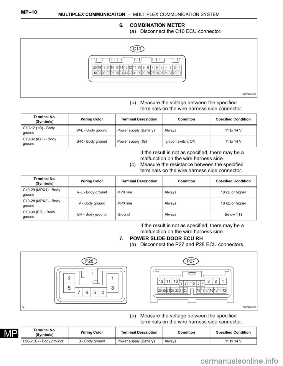
6. COMBINATION METER
(a) Disconnect the C10 ECU connector.
(b) Measure the voltage between the specified
terminals on the wire harness side connector.
If the result is not as specified, there may be a
malfunction on the wire harness side.
(c) Measure the resistance between the specified
terminals on the wire harness side connector.
If the result is not as specified, there may be a
malfunction on the wire harness side.
7. POWER SLIDE DOOR ECU RH
(a) Disconnect the P27 and P28 ECU connectors.
(b) Measure the voltage between the specified
terminals on the wire harness side connector.
B067255E03
Te r m i n a l N o .
(Symbols)Wiring Color Terminal Description Condition Specified Condition
C10-12 (+B) - Body
groundW-L - Body ground Power supply (Battery) Always 11 to 14 V
C10-32 (IG+) - Body
groundB-R - Body ground Power supply (IG) Ignition switch: ON 11 to 14 V
Te r m i n a l N o .
(Symbols)Wiring Color Terminal Description Condition Specified Condition
C10-29 (MPX1) - Body
groundR-L - Body ground MPX line Always 10 k
or higher
C10-28 (MPX2) - Body
groundV - Body ground MPX line Always 10 k
or higher
C10-30 (ES) - Body
groundBR - Body ground Ground Always Below 1
B067256E02
Te r m i n a l N o .
(Symbols)Wiring Color Terminal Description Condition Specified Condition
P28-2 (B) - Body ground B - Body ground Power supply (Battery) Always 11 to 14 V