Page 496 of 3000

ES–1902GR-FE ENGINE CONTROL SYSTEM – SFI SYSTEM
ES
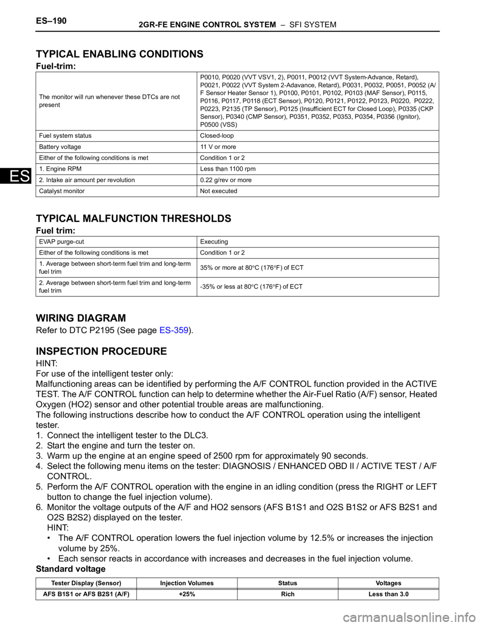
TYPICAL ENABLING CONDITIONS
Fuel-trim:
TYPICAL MALFUNCTION THRESHOLDS
Fuel trim:
WIRING DIAGRAM
Refer to DTC P2195 (See page ES-359).
INSPECTION PROCEDURE
HINT:
For use of the intelligent tester only:
Malfunctioning areas can be identified by performing the A/F CONTROL function provided in the ACTIVE
TEST. The A/F CONTROL function can help to determine whether the Air-Fuel Ratio (A/F) sensor, Heated
Oxygen (HO2) sensor and other potential trouble areas are malfunctioning.
The following instructions describe how to conduct the A/F CONTROL operation using the intelligent
tester.
1. Connect the intelligent tester to the DLC3.
2. Start the engine and turn the tester on.
3. Warm up the engine at an engine speed of 2500 rpm for approximately 90 seconds.
4. Select the following menu items on the tester: DIAGNOSIS / ENHANCED OBD II / ACTIVE TEST / A/F
CONTROL.
5. Perform the A/F CONTROL operation with the engine in an idling condition (press the RIGHT or LEFT
button to change the fuel injection volume).
6. Monitor the voltage outputs of the A/F and HO2 sensors (AFS B1S1 and O2S B1S2 or AFS B2S1 and
O2S B2S2) displayed on the tester.
HINT:
• The A/F CONTROL operation lowers the fuel injection volume by 12.5% or increases the injection
volume by 25%.
• Each sensor reacts in accordance with increases and decreases in the fuel injection volume.
Standard voltage
The monitor will run whenever these DTCs are not
presentP0010, P0020 (VVT VSV1, 2), P0011, P0012 (VVT System-Advance, Retard),
P0021, P0022 (VVT System 2-Adavance, Retard), P0031, P0032, P0051, P0052 (A/
F Sensor Heater Sensor 1), P0100, P0101, P0102, P0103 (MAF Sensor), P0115,
P0116, P0117, P0118 (ECT Sensor), P0120, P0121, P0122, P0123, P0220, P0222,
P0223, P2135 (TP Sensor), P0125 (Insufficient ECT for Closed Loop), P0335 (CKP
Sensor), P0340 (CMP Sensor), P0351, P0352, P0353, P0354, P0356 (Ignitor),
P0500 (VSS)
Fuel system status Closed-loop
Battery voltage 11 V or more
Either of the following conditions is met Condition 1 or 2
1. Engine RPM Less than 1100 rpm
2. Intake air amount per revolution 0.22 g/rev or more
Catalyst monitor Not executed
EVAP purge-cut Executing
Either of the following conditions is met Condition 1 or 2
1. Average between short-term fuel trim and long-term
fuel trim35% or more at 80
C (176F) of ECT
2. Average between short-term fuel trim and long-term
fuel trim-35% or less at 80
C (176F) of ECT
Tester Display (Sensor) Injection Volumes Status Voltages
AFS B1S1 or AFS B2S1 (A/F) +25% Rich Less than 3.0
Page 507 of 3000
2GR-FE ENGINE CONTROL SYSTEM – SFI SYSTEMES–201
ES
WIRING DIAGRAM
This troubleshooting procedure is based on the premise that the engine is started. If the engine is not
started, proceed to the problem symptoms table (See page ES-27).
INSPECTION PROCEDURE
(a) Connect the intelligent tester to the DLC3.
1PERFORM ACTIVE TEST BY INTELLIGENT TESTER
A162641E03
Page 512 of 3000
ES–2062GR-FE ENGINE CONTROL SYSTEM – SFI SYSTEM
ES
Monitor period of catalyst-damage-misfire (MIL blinks):
TYPICAL MALFUNCTION THRESHOLDS
Monitor period of emission-related-misfire:
Monitor period of catalyst-damage-misfire (MIL blinks):
MONITOR RESULT
Refer to CHECKING MONITOR STATUS (See page ES-19).
WIRING DIAGRAM
Refer to DTC P0351 for wiring diagram of the ignition system (See page ES-238).
Except above Crankshaft 1000 revolutions x 4
All of the following conditions 1, 2 and 3 are met Crankshaft 200 revolutions
1. Driving cycle 1st
2. Check mode OFF
3. Engine RPM Less than 2600 rpm
Except above (MIL blinks immediately) Crankshaft 200 revolutions x 3
Misfire rate 1% or more
Number of misfire per 200 revolutions 94 or more (varies with intake air amount and RPM)
Paired cylinders misfire (MIL blinks immediately) Detected
Page 529 of 3000
2GR-FE ENGINE CONTROL SYSTEM – SFI SYSTEMES–223
ES
WIRING DIAGRAM
INSPECTION PROCEDURE
HINT:
• DTCs P0327 and P0328 are for the bank 1 knock sensor circuit.
• DTCs P0332 and P0333 are for the bank 2 knock sensor circuit.
• Read freeze frame data using the intelligent tester. The ECM records vehicle and driving condition
information as freeze frame data the moment a DTC is stored. When troubleshooting, freeze frame
data can be helpful in determining whether the vehicle was running or stopped, whether the engine
was warmed up or not, whether the air-fuel ratio was lean or rich, as well as other data recorded at the
time of a malfunction.
A136096E05
Page 536 of 3000
ES–2302GR-FE ENGINE CONTROL SYSTEM – SFI SYSTEM
ES
WIRING DIAGRAM
A136097E06
Page 543 of 3000

2GR-FE ENGINE CONTROL SYSTEM – SFI SYSTEMES–237
ES
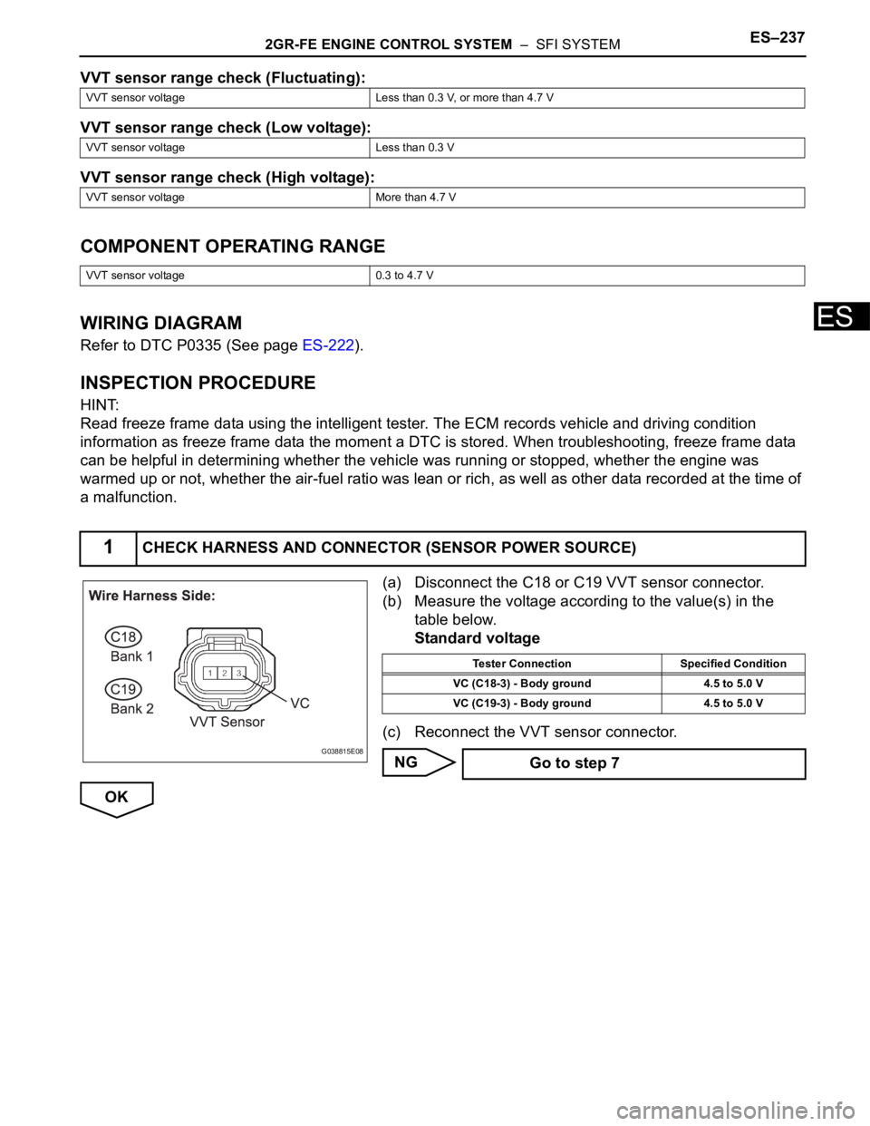
VVT sensor range check (Fluctuating):
VVT sensor range check (Low voltage):
VVT sensor range check (High voltage):
COMPONENT OPERATING RANGE
WIRING DIAGRAM
Refer to DTC P0335 (See page ES-222).
INSPECTION PROCEDURE
HINT:
Read freeze frame data using the intelligent tester. The ECM records vehicle and driving condition
information as freeze frame data the moment a DTC is stored. When troubleshooting, freeze frame data
can be helpful in determining whether the vehicle was running or stopped, whether the engine was
warmed up or not, whether the air-fuel ratio was lean or rich, as well as other data recorded at the time of
a malfunction.
(a) Disconnect the C18 or C19 VVT sensor connector.
(b) Measure the voltage according to the value(s) in the
table below.
Standard voltage
(c) Reconnect the VVT sensor connector.
NG
OK
VVT sensor voltage Less than 0.3 V, or more than 4.7 V
VVT sensor voltage Less than 0.3 V
VVT sensor voltage More than 4.7 V
VVT sensor voltage 0.3 to 4.7 V
1CHECK HARNESS AND CONNECTOR (SENSOR POWER SOURCE)
G038815E08
Tester Connection Specified Condition
VC (C18-3) - Body ground 4.5 to 5.0 V
VC (C19-3) - Body ground 4.5 to 5.0 V
Go to step 7
Page 547 of 3000

2GR-FE ENGINE CONTROL SYSTEM – SFI SYSTEMES–241
ES
HINT:
• These DTCs indicate malfunctions relating to the primary circuit.
• If DTC P0351 is set, check the No. 1 ignition coil with igniter circuit.
• If DTC P0352 is set, check the No. 2 ignition coil with igniter circuit.
• If DTC P0353 is set, check the No. 3 ignition coil with igniter circuit.
• If DTC P0354 is set, check the No. 4 ignition coil with igniter circuit.
• If DTC P0355 is set, check the No. 5 ignition coil with igniter circuit.
• If DTC P0356 is set, check the No. 6 ignition coil with igniter circuit.
DESCRIPTION
A Direct Ignition System (DIS) is used on this vehicle.
The DIS is a 1-cylinder ignition system in which each cylinder is ignited by one ignition coil and one spark
plug is connected to the end of each secondary wiring. High-voltage is generated in the secondary wiring
and then applied directly to each spark plug. The sparks of the spark plugs pass from the center
electrodes to the ground electrodes.
The ECM determines the ignition timing and transmits the ignition (IGT) signals to each cylinder. Using the
IGT signal, the ECM turns the power transistor inside the igniter on and off. The power transistor, in turn,
switches on and off the current to the primary coil. When the current to the primary coil is cut off, high-
voltage is generated in the secondary coil. This voltage is applied to the spark plugs, causing them to
spark inside the cylinders. As the ECM cuts the current to the primary coil off, the igniter sends back an
ignition confirmation (IGF) signal to the ECM, for each cylinder ignition.
DTC P0351 Ignition Coil "A" Primary / Secondary Circuit
DTC P0352 Ignition Coil "B" Primary / Secondary Circuit
DTC P0353 Ignition Coil "C" Primary / Secondary Circuit
DTC P0354 Ignition Coil "D" Primary / Secondary Circuit
DTC P0355 Ignition Coil "E" Primary / Secondary Circuit
DTC P0356 Ignition Coil "F" Primary / Secondary Circuit
Page 552 of 3000
ES–2462GR-FE ENGINE CONTROL SYSTEM – SFI SYSTEM
ES
WIRING DIAGRAM
A140713E03