Page 432 of 3000
ES–1262GR-FE ENGINE CONTROL SYSTEM – SFI SYSTEM
ES
WIRING DIAGRAM
INSPECTION PROCEDURE
HINT:
Read freeze frame data using the intelligent tester. The ECM records vehicle and driving condition
information as freeze frame data the moment a DTC is stored. When troubleshooting, freeze frame data
can be helpful in determining whether the vehicle was running or stopped, whether the engine was
warmed up or not, whether the air-fuel ratio was lean or rich, as well as other data recorded at the time of
a malfunction.
(a) Connect the intelligent tester to the DLC3.
(b) Start the engine.
(c) Turn the tester on.
(d) Select the following menu items: DIAGNOSIS /
ENHANCED OBD II / DATA LIST / PRIMARY / MAF.
(e) Read the values displayed on the tester.
1READ VALUE OF INTELLIGENT TESTER (MASS AIR FLOW RATE)
A117876E09
Page 437 of 3000

2GR-FE ENGINE CONTROL SYSTEM – SFI SYSTEMES–131
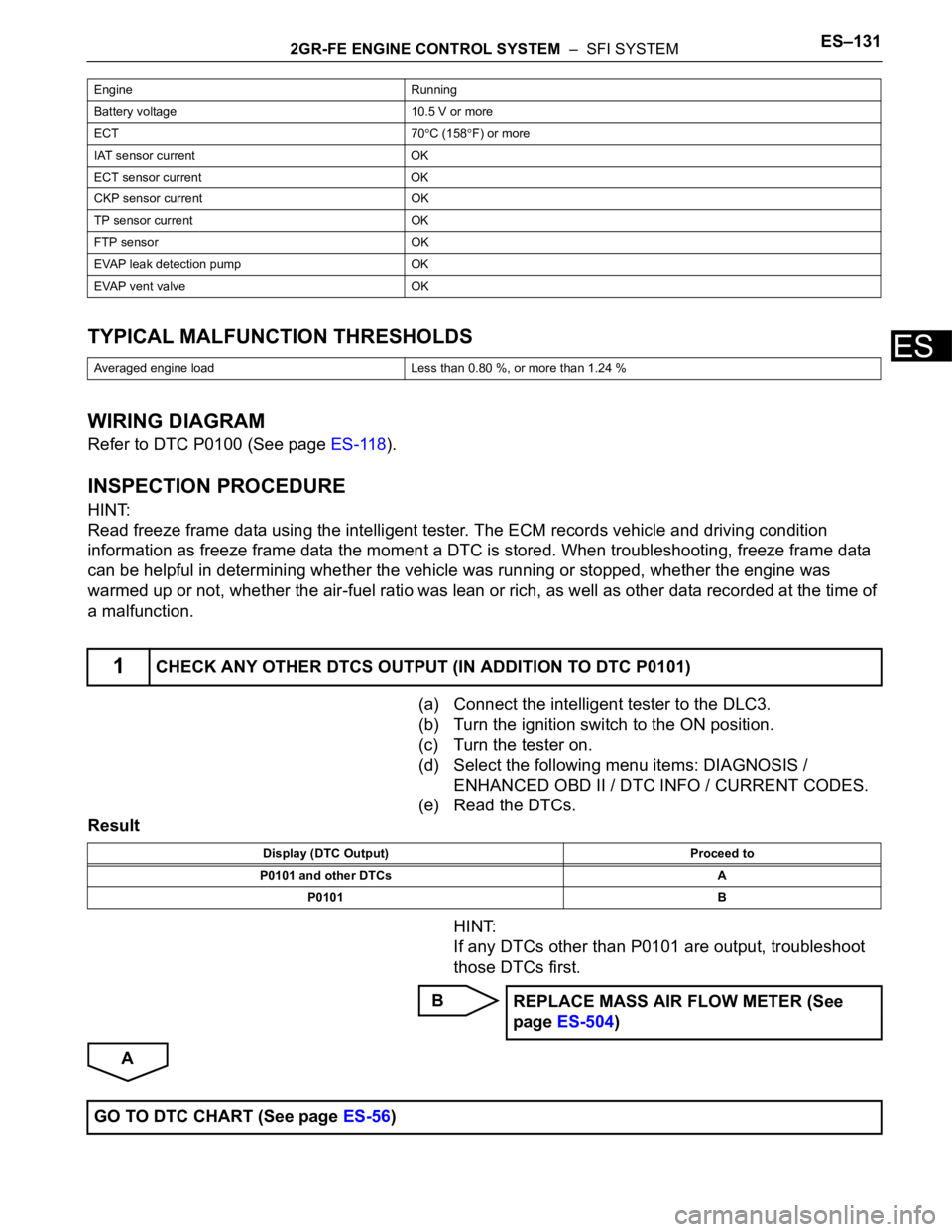
ESTYPICAL MALFUNCTION THRESHOLDS
WIRING DIAGRAM
Refer to DTC P0100 (See page ES-118).
INSPECTION PROCEDURE
HINT:
Read freeze frame data using the intelligent tester. The ECM records vehicle and driving condition
information as freeze frame data the moment a DTC is stored. When troubleshooting, freeze frame data
can be helpful in determining whether the vehicle was running or stopped, whether the engine was
warmed up or not, whether the air-fuel ratio was lean or rich, as well as other data recorded at the time of
a malfunction.
(a) Connect the intelligent tester to the DLC3.
(b) Turn the ignition switch to the ON position.
(c) Turn the tester on.
(d) Select the following menu items: DIAGNOSIS /
ENHANCED OBD II / DTC INFO / CURRENT CODES.
(e) Read the DTCs.
Result
HINT:
If any DTCs other than P0101 are output, troubleshoot
those DTCs first.
B
A
Engine Running
Battery voltage 10.5 V or more
ECT 70
C (158F) or more
IAT sensor current OK
ECT sensor current OK
CKP sensor current OK
TP sensor current OK
FTP sensor OK
EVAP leak detection pump OK
EVAP vent valve OK
Averaged engine load Less than 0.80 %, or more than 1.24 %
1CHECK ANY OTHER DTCS OUTPUT (IN ADDITION TO DTC P0101)
Display (DTC Output) Proceed to
P0101 and other DTCs A
P0101 B
REPLACE MASS AIR FLOW METER (See
page ES-504)
GO TO DTC CHART (See page ES-56)
Page 440 of 3000

ES–1342GR-FE ENGINE CONTROL SYSTEM – SFI SYSTEM
ES
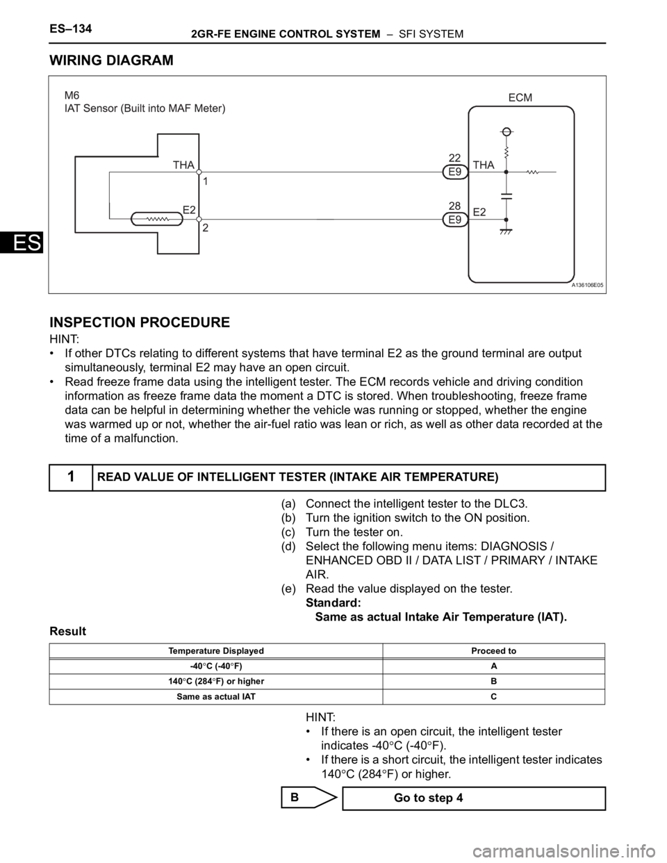
WIRING DIAGRAM
INSPECTION PROCEDURE
HINT:
• If other DTCs relating to different systems that have terminal E2 as the ground terminal are output
simultaneously, terminal E2 may have an open circuit.
• Read freeze frame data using the intelligent tester. The ECM records vehicle and driving condition
information as freeze frame data the moment a DTC is stored. When troubleshooting, freeze frame
data can be helpful in determining whether the vehicle was running or stopped, whether the engine
was warmed up or not, whether the air-fuel ratio was lean or rich, as well as other data recorded at the
time of a malfunction.
(a) Connect the intelligent tester to the DLC3.
(b) Turn the ignition switch to the ON position.
(c) Turn the tester on.
(d) Select the following menu items: DIAGNOSIS /
ENHANCED OBD II / DATA LIST / PRIMARY / INTAKE
AIR.
(e) Read the value displayed on the tester.
Standard:
Same as actual Intake Air Temperature (IAT).
Result
HINT:
• If there is an open circuit, the intelligent tester
indicates -40
C (-40F).
• If there is a short circuit, the intelligent tester indicates
140
C (284F) or higher.
B
1READ VALUE OF INTELLIGENT TESTER (INTAKE AIR TEMPERATURE)
A136106E05
Temperature Displayed Proceed to
-40
C (-40F) A
140
C (284F) or higher B
Same as actual IAT C
Go to step 4
Page 445 of 3000

2GR-FE ENGINE CONTROL SYSTEM – SFI SYSTEMES–139
ES
TYPICAL ENABLING CONDITIONS
All:
After engine stop:
After cold engine start:
TYPICAL MALFUNCTION THRESHOLDS
After engine stop:
After cold engine start:
WIRING DIAGRAM
Refer to DTC P0110 (See page ES-126).
INSPECTION PROCEDURE
(a) Connect the intelligent tester to the DLC3.
(b) Turn the ignition switch to the ON position.
(c) Turn the tester on.
(d) Enter the following menus: DIAGNOSIS / ENHANCED
OBD II / DTC INFO / CURRENT CODES.
Required Sensors / Components (Main) Intake Air Temperature (IAT) sensor
Required Sensors / Components (Sub) -
Frequency of Operation Once per driving cycle
Duration 5 hours
MIL Operation 2 driving cycles
Sequence of Operation None
Monitor runs whenever following DTCs are not present None
Time after engine start 10 seconds or more
Battery voltage 10.5 V or more
ECT sensor OK
ECT change since engine stopped Less than 180
C (356F)
ECT before engine stop 70
C (158F) or more
Time that MAF is low before engine stop 70 minutes
Accumulated MAF amount before engine stop 3774 g or more
Key-off duration 30 minutes
Key-off duration 5 hours
Time after engine start 10 seconds or more
ECT sensor OK
ECT 70
C (158F) or more
Accumulated MAF amount 3774 g or more
One of the following conditions 1 or 2 is met: -
1. Duration while engine load is low 120 seconds or more
2. Duration while engine load is high 10 seconds or more
IAT change Less than 1
C (2F)
IAT change Less than 1
C (2F)
1CHECK ANY OTHER DTCS OUTPUT (IN ADDITION TO DTC P0111)
Page 448 of 3000
ES–1422GR-FE ENGINE CONTROL SYSTEM – SFI SYSTEM
ES
TYPICAL ENABLING CONDITIONS
TYPICAL MALFUNCTION THRESHOLDS
P0115:
P0117:
P0118:
COMPONENT OPERATING RANGE
WIRING DIAGRAM
INSPECTION PROCEDURE
HINT:
• If other DTCs relating to different systems that have terminal E2 as the ground terminal are output
simultaneously, terminal E2 may have an open circuit.
Required Sensors / Components (Main) Engine coolant temperature sensor
Required Sensors / Components (Related) -
Frequency of Operation Continuous
Duration 0.5 seconds
MIL Operation Immediate
Sequence of Operation None
The monitor will run whenever these DTCs are not
presentNone
Engine coolant temperature sensor voltage Less than 0.14 V or more than 4.91 V
Engine coolant temperature sensor voltage Less than 0.14 V [More than 140
C (284F)]
Engine coolant temperature sensor voltage More than 4.91 V [Less than -40
C (-40F)]
Engine coolant temperature sensor voltage 0.14 V to 4.91 V [-40 to 140
C (-40 to 284F)]
A072925E48
Page 463 of 3000

2GR-FE ENGINE CONTROL SYSTEM – SFI SYSTEMES–157
ES
WIRING DIAGRAM
INSPECTION PROCEDURE
HINT:
• If other DTCs relating to different systems that have terminal E2 as the ground terminal are output
simultaneously, terminal E2 may have an open circuit.
• Read freeze frame data using the intelligent tester. The ECM records vehicle and driving condition
information as freeze frame data the moment a DTC is stored. When troubleshooting, freeze frame
data can be helpful in determining whether the vehicle was running or stopped, whether the engine
was warmed up or not, whether the air-fuel ratio was lean or rich, as well as other data recorded at the
time of a malfunction.
(a) Connect the intelligent tester to the DLC3.
(b) Turn the ignition switch to the ON position and turn the
intelligent tester on.
(c) Select the following menu items: DIAGNOSIS /
ENHANCED OBD II / DATA LIST / ETCS / THROTTLE
POS and THROTTLE POS #2.
(d) Check the values displayed on the tester.
Result
1READ VALUE OF INTELLIGENT TESTER (THROTTLE POS AND THROTTLE POS #2)
A085458E27
TP#1 (VTA1)
When AP ReleasedTP#2 (VTA2)
When AP ReleasedTP#1 (VTA1)
When AP
DepressedTP#2 (VTA2)
When AP
DepressedTrouble Area Proceed to
0%Between 0 V and 0.2
V0%Between 0 V and 0.2
VVC circuit open A
100%Between 4.5 V and
5.0 V100 %Between 4.5 V and
5.0 VE2 circuit open A
0% or 100%Between 2.1 V and
3.1 V
(Fail-safe)0% or 100%Between 2.1 V and
3.1 V
(Fail-safe)VTA1 circuit open or
ground shortA
Page 468 of 3000

ES–1622GR-FE ENGINE CONTROL SYSTEM – SFI SYSTEM
ES
DESCRIPTION
Refer to DTC P0115 (See page ES-133).
MONITOR DESCRIPTION
The resistance of the ECT sensor varies in proportion to the actual ECT. The ECM supplies a constant
voltage to the sensor and monitors the signal output voltage of the sensor. The signal voltage output
varies according to the changing resistance of the sensor. After the engine is started, the ECT is
monitored through this signal. If the ECT sensor indicates that the engine is not yet warm enough for
closed-loop fuel control, despite a specified period of time having elapsed since the engine was started,
the ECM interprets this as a malfunction in the sensor or cooling system and sets the DTC.
Example:
The ECT is 0
C (32F) at engine start. After 5 minutes running time, the ECT sensor still indicates that the
engine is not warm enough to begin closed-loop fuel (air-fuel ratio feedback) control. The ECM interprets
this as a malfunction in the sensor or cooling system and sets the DTC.
MONITOR STRATEGY
TYPICAL ENABLING CONDITIONS
TYPICAL MALFUNCTION THRESHOLDS
WIRING DIAGRAM
Refer to DTC P0115 (See page ES-134).
DTC P0125Insufficient Coolant Temperature for Closed
Loop Fuel Control
DTC No. DTC Detection Condition Trouble Area
P0125Engine coolant temperature (ECT) does not reach
closed-loop enabling temperature for 20 minutes (this
period varies with engine start ECT)• Cooling system
• Engine coolant temperature sensor
• Thermostat
Related DTCs P0125: Insufficient engine coolant temperature for closed-loop fuel control
Required Sensors / Components (Main) Thermostat, cooling system
Required Sensors / Components (Related) Engine coolant temperature sensor and mass air flow meter
Frequency of Operation Continuous
Duration78 seconds: Engine coolant temperature at engine start -8.34
C (17F) or more
131.3 seconds: Engine coolant temperature at engine start -19.45 to -8.34C (-3 to
17
F)
20 minutes: Engine coolant temperature at engine start less than -19.45
C (-3F)
MIL Operation 2 driving cycles
Sequence of Operation None
The monitor will run whenever these DTCs are not
presentP0100, P0101, P0102, P0103 (MAF) sensor, P0110, P0111, P0112, P0113 (IAT
sensor), P0115, P0116, P0117, P0118 (ECT sensor)
Fuel cut OFF
Engine Running
Time until actual engine coolant temperature reaches
closed-loop fuel control enabling temperature78 seconds or more: Engine coolant temperature at engine start -8.34
C (17F) or
more
131.3 seconds or more: Engine coolant temperature at engine start -19.45 to -8.34
C
(-3 to 17
F)
20 minutes or more: Engine coolant temperature at engine start less than -19.45C (-
3
F)
Page 481 of 3000
2GR-FE ENGINE CONTROL SYSTEM – SFI SYSTEMES–175
ES
WIRING DIAGRAM
A136092E05