2007 TOYOTA SIENNA wiring
[x] Cancel search: wiringPage 334 of 3000

ES–4062GR-FE ENGINE CONTROL SYSTEM – SFI SYSTEM
ES
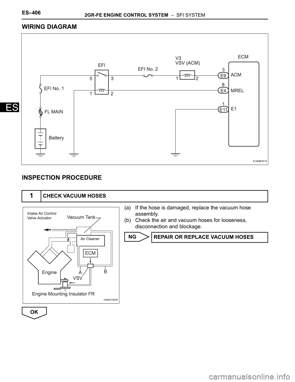
WIRING DIAGRAM
INSPECTION PROCEDURE
(a) If the hose is damaged, replace the vacuum hose
assembly.
(b) Check the air and vacuum hoses for looseness,
disconnection and blockage.
NG
OK
1CHECK VACUUM HOSES
A136867E18
G042514E04
REPAIR OR REPLACE VACUUM HOSES
Page 391 of 3000

2GR-FE ENGINE CONTROL SYSTEM – SFI SYSTEMES–85
ES
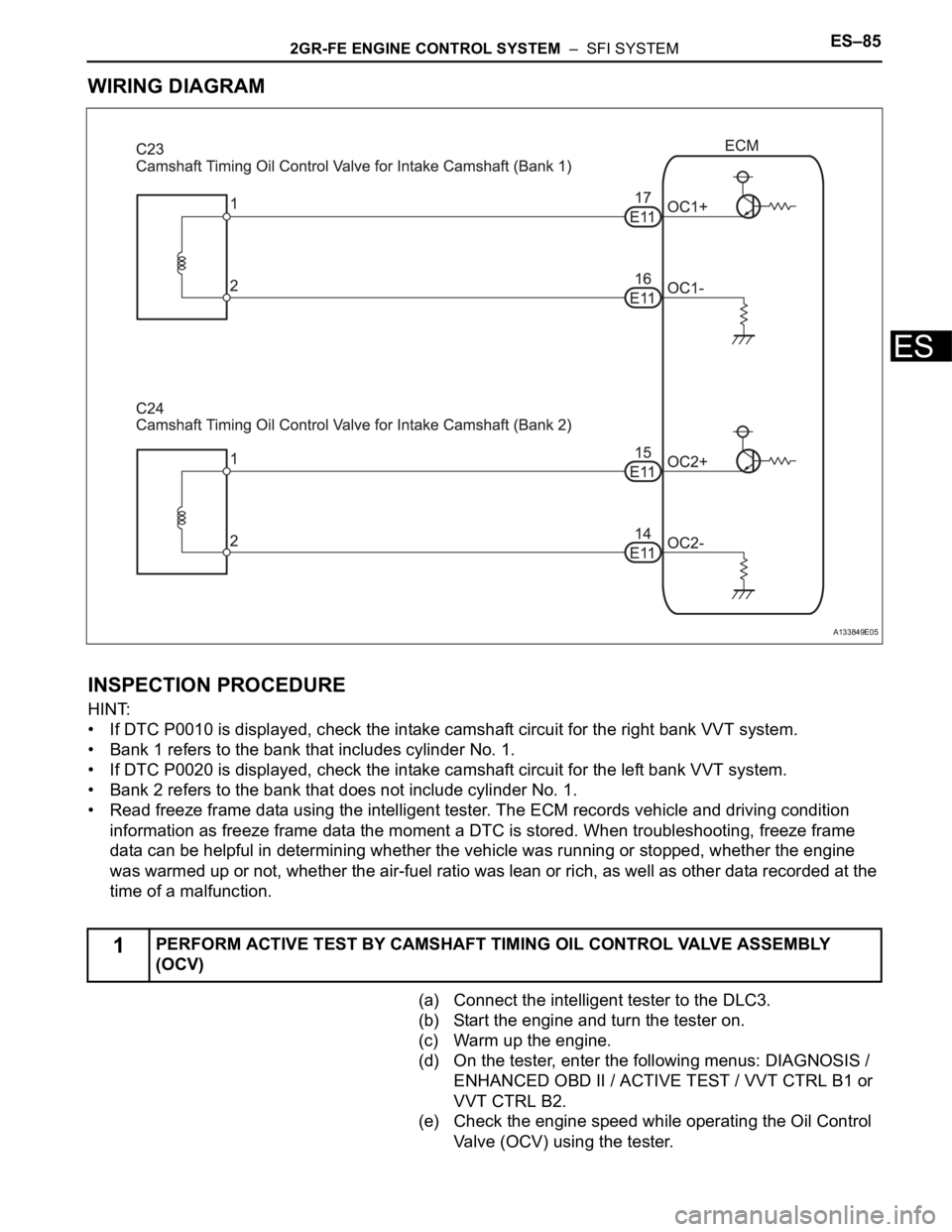
WIRING DIAGRAM
INSPECTION PROCEDURE
HINT:
• If DTC P0010 is displayed, check the intake camshaft circuit for the right bank VVT system.
• Bank 1 refers to the bank that includes cylinder No. 1.
• If DTC P0020 is displayed, check the intake camshaft circuit for the left bank VVT system.
• Bank 2 refers to the bank that does not include cylinder No. 1.
• Read freeze frame data using the intelligent tester. The ECM records vehicle and driving condition
information as freeze frame data the moment a DTC is stored. When troubleshooting, freeze frame
data can be helpful in determining whether the vehicle was running or stopped, whether the engine
was warmed up or not, whether the air-fuel ratio was lean or rich, as well as other data recorded at the
time of a malfunction.
(a) Connect the intelligent tester to the DLC3.
(b) Start the engine and turn the tester on.
(c) Warm up the engine.
(d) On the tester, enter the following menus: DIAGNOSIS /
ENHANCED OBD II / ACTIVE TEST / VVT CTRL B1 or
VVT CTRL B2.
(e) Check the engine speed while operating the Oil Control
Valve (OCV) using the tester.
1PERFORM ACTIVE TEST BY CAMSHAFT TIMING OIL CONTROL VALVE ASSEMBLY
(OCV)
A133849E05
Page 395 of 3000

2GR-FE ENGINE CONTROL SYSTEM – SFI SYSTEMES–89
ES
3) After above conditions 1) and 2) are met, the OCV is forcibly activated 63 times or more.
DTCs P0011 and P0021 (Advanced Cam Timing) are detected with 1 trip detection logic.
DTCs P0012 and P0022 (Retarded Cam Timing) are detected with 2 trip detection logic.
These DTCs indicate that the VVT controller cannot operate properly due to OCV malfunctions or the
presence of foreign objects in the OCV.
The monitor will not run unless the following conditions are met:
- The engine is warm (the engine coolant temperature is 75
C [167F] or more).
- The vehicle has been driven at more than 40 mph (64 km/h) for 3 minutes.
- The engine has idled for 3 minutes.
MONITOR STRATEGY
TYPICAL ENABLING CONDITIONS
TYPICAL MALFUNCTION THRESHOLDS
P0011, P0021:
P0012, P0022:
If the difference between the target and actual camshaft timings is greater than the specified value, the
ECM operates the VVT actuator.
Then, the ECM monitors the camshaft timing change for 5 seconds.
WIRING DIAGRAM
Refer to DTC P0010 (See page ES-77).
INSPECTION PROCEDURE
Related DTCsP0011: Advanced intake camshaft timing (bank 1)
P0012: Retarded intake camshaft timing (bank 1)
P0021: Advanced intake camshaft timing (bank 2)
P0022: Retarded intake camshaft timing (bank 2)
Required sensors / components (Main) VVT OCV, VVT Actuator
Required sensors / components (Related) Crankshaft position sensor, Camshaft position sensor, ECT sensor
Frequency of operation Once per driving cycles
Duration Less than 10 seconds
MIL operationP0011 and P0021: Immediate
P0012 and P0022: 2 driving cycles
Sequence operation None
The monitor will run whenever these DTCs are not
presentP0100, P0101, P0102, P0103 (MAF Sensor), P0115, P0116, P0117, P0118 (ECT
Sensor), P0125 (Insufficient ECT for Closed Loop), P0335 (CKP Sensor), P0340
(CMP Sensor), P0351, P0352, P0353, P0354, P0355, P0356 (Ignitor)
Battery voltage 11 V or more
Engine RPM 500 to 4000 rpm
ECT 75 to 100
C (167 to 212F)
Duration of actual valve timing and target valve timing More than 5
CA (Crankshaft angle)
Valve timing No change in advanced valve timing
Duration of actual valve timing and target valve timing More than 5
CA (Crankshaft angle)
Valve timing No change in retarded valve timing
Abnormal bankAdvanced timing over
(Valve timing is out of specified range)Retarded timing over
(Valve timing is out of specified range)
Bank 1 P0011 P0012
Bank 2 P0021 P0022
Page 403 of 3000

2GR-FE ENGINE CONTROL SYSTEM – SFI SYSTEMES–97
ES
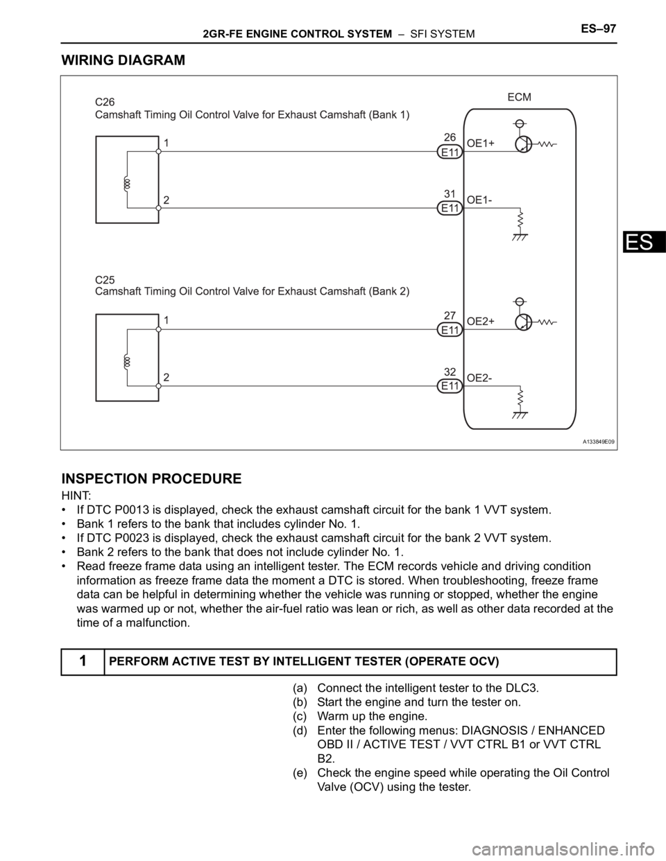
WIRING DIAGRAM
INSPECTION PROCEDURE
HINT:
• If DTC P0013 is displayed, check the exhaust camshaft circuit for the bank 1 VVT system.
• Bank 1 refers to the bank that includes cylinder No. 1.
• If DTC P0023 is displayed, check the exhaust camshaft circuit for the bank 2 VVT system.
• Bank 2 refers to the bank that does not include cylinder No. 1.
• Read freeze frame data using an intelligent tester. The ECM records vehicle and driving condition
information as freeze frame data the moment a DTC is stored. When troubleshooting, freeze frame
data can be helpful in determining whether the vehicle was running or stopped, whether the engine
was warmed up or not, whether the air-fuel ratio was lean or rich, as well as other data recorded at the
time of a malfunction.
(a) Connect the intelligent tester to the DLC3.
(b) Start the engine and turn the tester on.
(c) Warm up the engine.
(d) Enter the following menus: DIAGNOSIS / ENHANCED
OBD II / ACTIVE TEST / VVT CTRL B1 or VVT CTRL
B2.
(e) Check the engine speed while operating the Oil Control
Valve (OCV) using the tester.
1PERFORM ACTIVE TEST BY INTELLIGENT TESTER (OPERATE OCV)
A133849E09
Page 407 of 3000

2GR-FE ENGINE CONTROL SYSTEM – SFI SYSTEMES–101
ES
MONITOR STRATEGY
TYPICAL ENABLING CONDITIONS
TYPICAL MALFUNCTION THRESHOLDS
Advanced camshaft timing:
Retarded camshaft timing:
If the difference between the target and actual camshaft timings is greater than the specified value, the
ECM operates the VVT actuator.
Then, the ECM monitors the camshaft timing change for 5 seconds.
WIRING DIAGRAM
Refer to DTC P0013 (See page ES-89).
INSPECTION PROCEDURE
HINT:
• If DTC P0014 or P0015 is displayed, check the bank 1 VVT system circuit.
• Bank 1 refers to the bank that includes cylinder No. 1.
• If DTC P0024 or P0025 is displayed, check the bank 2 VVT system circuit.
• Bank 2 refers to the bank that does not include cylinder No. 1.
Related DTCsP0014: Advanced exhaust camshaft timing (bank 1)
P0015: Retarded exhaust camshaft timing (bank 1)
P0024: Advanced exhaust camshaft timing (bank 2)
P0025: Retarded exhaust camshaft timing (bank 2)
Required Sensors / Components (Main) VVT OCV and VVT Actuator
Required Sensors / Components (Related)P0014 and P0015:
Exhaust camshaft control actuator bank 1
Exhaust OCV bank 1
P0024 and P0025:
Exhaust camshaft control actuator bank 2
Exhaust OCV bank 2
Frequency of Operation Continuously
Duration Less than 10 seconds
MIL OperationP0014 and P0024: Immediate
P0015 and P0025: 2 driving cycles
Sequence of Operation None
The monitor will run whenever these DTCs are not
presentNone
Battery voltage 11 V or more
Engine RPM 500 to 4000 rpm
Engine coolant temperature 75 to 100
C (167 to 212F)
Valve timing No change
Valve timing Advanced position
Valve timing No change
Valve timing Retarded position
Abnormal bankAdvanced timing over
(Valve timing is out of specified range)Retarded timing over
(Valve timing is out of specified range)
Bank 1 P0014 P0015
Bank 2 P0024 P0025
Page 413 of 3000

2GR-FE ENGINE CONTROL SYSTEM – SFI SYSTEMES–107
ES
MONITOR STRATEGY
TYPICAL ENABLING CONDITIONS
All:
P0016 and P0018:
P0017 and P0019:
TYPICAL MALFUNCTION THRESHOLDS
P0016 and P0018:
P0017 and P0019:
WIRING DIAGRAM
Refer to DTC P0335 (See page ES-222).
INSPECTION PROCEDURE
HINT:
Read freeze frame data using the intelligent tester. The ECM records vehicle and driving condition
information as freeze frame data the moment a DTC is stored. When troubleshooting, freeze frame data
can be helpful in determining whether the vehicle was running or stopped, whether the engine was
warmed up or not, whether the air-fuel ratio was lean or rich, as well as other data recorded at the time of
a malfunction.
Related DTCsP0016: Deviation in crankshaft position sensor signal and camshaft position sensor
signal (Bank 1)
P0017: Deviation in crankshaft position sensor signal and camshaft position sensor
signal (Bank 1 Sensor 2)
P0018: Deviation in crankshaft position sensor signal and camshaft position sensor
signal (Bank 2)
P0019: Deviation in crankshaft position sensor signal and camshaft position sensor
signal (Bank 2 Sensor 2)
Required Sensors / Components (Main)P0016 and P0018: VVT actuator
P0017 and P0019: Timing chain/belt
Required Sensors / Components (Related)P0016 and P0018: Camshaft position sensor, Crankshaft position sensor
P0017 and P0019: None
Frequency of Operation Once per driving cycle
Duration Less than 60 seconds
MIL Operation 2 driving cycles
Sequence of Operation None
The monitor will run whenever these DTCs are not
presentP0011, P0012 (VVT System 1-Advance, Retard), P0021, P0022 (VVT System 2-
Adavance, Retard), P0115, P0116, P0117, P0118 (ECT Sensor)
Engine RPM 500 to 1000 rpm
VVT feedback mode Executing
VVT Maximum advanced position
Engine RPM 500 to 1000 rpm
One of the following conditions is met: Condition 1 or 2
1. VVT learning value at maximum retarded valve
timingLess than 18.5
CA
2. VVT learning value at maximum retarded valve
timingMore than 43.5
CA
One of the following conditions is met: Condition 1 or 2
1. VVT learning value Less than 77
CA
2. VVT learning value More than 102
CA
Page 417 of 3000

2GR-FE ENGINE CONTROL SYSTEM – SFI SYSTEMES–111
ES
P0032 and P0052:
TYPICAL MALFUNCTION THRESHOLDS
P0031 and P0051:
P0032 and P0052:
COMPONENT OPERATING RANGE
MONITOR RESULT
Refer to CHECKING MONITOR STATUS (See page ES-19).
WIRING DIAGRAM
Refer to DTC P2195 (See page ES-359).
INSPECTION PROCEDURE
HINT:
Read freeze frame data using the intelligent tester. The ECM records vehicle and driving condition
information as freeze frame data the moment a DTC is stored. When troubleshooting, freeze frame data
can be helpful in determining whether the vehicle was running or stopped, whether the engine was
warmed up or not, whether the air-fuel ratio was lean or rich, as well as other data recorded at the time of
a malfunction.
Time after engine starts 10 seconds or more
Time after engine starts 10 seconds or more
Heater current Less than 0.8 A
Hybrid IC high current limit port Fail
A/F sensor heater current 0.8 A or more
Page 425 of 3000

2GR-FE ENGINE CONTROL SYSTEM – SFI SYSTEMES–119
ES
TYPICAL ENABLING CONDITIONS
All:
P0037 and P0057:
P0038 and P0058 Case 1:
P0038 and P0058 Case 2:
P0141 and P0161:
TYPICAL MALFUNCTION THRESHOLDS
P0037 and P0057:
P0038 and P0058:
P0141 and P0161 (Heater performance monitor check):
COMPONENT OPERATING RANGE
MONITOR RESULT
Refer to CHECKING MONITOR STATUS (See page ES-19).
WIRING DIAGRAM
Refer to DTC P0136 (See page ES-167).
INSPECTION PROCEDURE
HINT:
• If other DTCs relating to different systems that have terminal E2 as the ground terminal are output
simultaneously, terminal E2 may have an open circuit.
Monitor runs whenever following DTCs are not present None
Battery voltage 10.5 to 20 V
Battery voltage 10.5 V or more
Engine Running
Sta r t e r OF F
Battery voltage 10.5 to 20 V
One of the following conditions is met: Condition A or B
A. All of the following conditions are met: Conditions 1, 2, 3, 4 and 5
1. Battery voltage 10.5 V or more
2. Fuel cut OFF
3. Time after fuel cut ON to OFF 30 seconds or more
4. Accumulated heater ON time 100 seconds or more
5. Learned heater OFF current operation Completed
B. Duration that rear heated oxygen sensor impedance is less than 15
k
2 seconds or more
Heater Current - Learned heater OFF current Less than 0.3 A
Learned heater OFF current More than 2 A
Heater Current - Learned heater OFF current 2 A or more
Accumulated heater resistance Varies with sensor element temperature (Example: More than 23
)
Heated Oxygen (HO2) sensor heater current0.4 to 1 A (when engine idles, HO2 sensor warmed up and battery voltage 11 to 14
V)